Correlation-Based Device Energy-Efficient Dynamic Multi-Task Offloading for Mobile Edge Computing
Abstract
Task offloading to mobile edge computing (MEC) has emerged as a key technology to alleviate the computation workloads of mobile devices and decrease service latency for the computation-intensive applications. Device battery consumption is one of the limiting factors needs to be considered during task offloading. In this paper, multi-task offloading strategies have been investigated to improve device energy efficiency. Correlations among tasks in time domain as well as task domain are proposed to be employed to reduce the number of tasks to be transmitted to MEC. Furthermore, a binary decision tree based algorithm is investigated to jointly optimize the mobile device clock frequency, transmission power, structure and number of tasks to be transmitted. MATLAB based simulation is employed to demonstrate the performance of our proposed algorithm. It is observed that the proposed dynamic multi-task offloading strategies can reduce the total energy consumption at device along various transmit power versus noise power point compared with the conventional one.
Index Terms:
Task offloading, device energy efficiency, MEC, correlation, task splitting.I Introduction
With the continuous development of mobile communication technology and the rapid development of mobile Internet, mobile terminals represented by smart phones, tablet computers, laptop, and smart assistants have been widely used. But the mobile terminal receives limiting factors such as volume, weight, performance, power, etc. Its working ability is still in a serious and tedious state, which cannot meet the increasing demand of people. Although the mobile terminal has made great progress in hardware technology (for example, the continuous replacement of CPU/GPU, the continuous improvement of chip manufacturing process from 28nm to 14nm to the current 7nm, 5nm[1], etc.), but it is still far from what people need. Moreover, with the emergence of new concepts such as autonomous driving, telemedicine, and Industry 4.0 which need ultra reliability, low latency[2], ordinary equipment is even more unable to support their operations. Meanwhile, with the emergence of machine learning, artificial intelligence and other emerging technologies[3], the rapid development of image recognition, speech recognition and other applications, virtual reality and augmented reality game applications are emerging in endlessly. The operation of these applications requires a large amount of computing resources and storage resources, and they are all computationally intensive applications at a time. Due to the limitation of mobile terminals or some other devices, when computationally intensive applications[3] are running on smart terminals, the endurance of the terminal and the performance of the application are very problematic. How to solve this problem of resource limitation and energy consumption has become a huge challenge today.
Most of the literature suggests to change the task allocation method, transmission power, clock frequency to optimize the task offloading algorithm. In [4]–[5], authors proposed task splitting, which is a way to change the task structure to reduce the latency and improve the local device energy efficiency. However, they only split the task, but did not consider the redundancy of sources. In this paper, we propose to split task to the smallest executable task, named as unit, and then select the unit by using the correlation between them. Furthermore, both time and task domain correlation is considered in our work to selected the necessary tasks to be processed.
II Problem Formulation and System Models
In this section, the definition of task and unit will be introduced first to help to understand the proposed models. Both task and unit are the process of collecting data, processing data, and sending instructions, but unit is the smallest section that can form a task, and unit cannot be divided anymore. That means task can be composed of one or more units, and a task can be split into one or more units.
Consider devices (users), denoted by a set of , and device has tasks at the same time, , denoted by a set of , each task in the tasks is composed of different unit, denoted by a set of and . After some tasks are split, some identical units may be generated, so the correlation of task domain came into being. In our work, it is proposed to use the correlation between units to improve the energy-efficient of local device and reduce the latency. Moreover, it is assumed here that devices communicate with MEC server orthogonally. The main target here is to improve the energy efficiency of local devices when fulfil the extremely severe latency requirements of each unit and each device.
The energy cost minimization problem is formulated as:
| (1) |
Subject to
| (2) |
represents the local energy consumption of user , represents the latency of unit of user n processed on MEC, represents the latency of unit k of user processed on local device, represents the latency requirement of unit , represents the collection of all tasks processed on the MEC, and represents the collection of all units processed on the local device, represents the latency of user , represents the latency requirement of user , represents the computation capability of user , such as the number of CPU cycles per second, represents the transmission power of user , and indicate the maximum value of and respectively.
, , , C1 and C2 are to limit the latency of each task to not exceed the requirements, C3 is to limit the user’s overall latency does not exceed the requirements, C4 is to limit the processing power of the local device not to exceed its maximum processing power, C5 is to limit the transmission power of the local device not to exceed its maximum transmission power.
II-A Transmission Model
When the interference is not considered, the signal-to-noise ratio (SNR) of user n is
| (3) |
and then, the transmission rate (uplink) of user is calculated as:
| (4) |
In (3) and (4), represents the bandwidth of this channel, represent the channel gain of user n to MEC, and represents the noise spectral density, represents the transmission power of user . Because the amount of data that needs to be offloaded is much larger than the amount of data that needs to be downloaded, so the downlink is ignored in this paper[6, 7].
II-B Computation Model
Let represent the CPU cycle required to calculate the unit (unit of user ), represents the computation input data (in bits) of the th unit of th user of local devices.
Local Computing
when user chooses to process locally, use to represent the CPU clock speed of user’s device, so the latency in local for computing can be represented as:
| (5) |
where denotes the time required to complete unit of user in local device.
The energy required to complete unit in local device can be expressed by the following formula
| (6) |
In this case, is the effective switched capacitance depending on the chip architecture[8].
II-B1 MEC Computing
when a user decides to offload tasks to MEC, and transmit a unit through a wireless network, the corresponding transmission latency and energy consumption will be generated. According to the communication model, the uplink transmission latency when user offload the task is:
| (7) |
and the energy required to transmit unit can be expressed by the following formula:
| (8) |
where represents the time required to transmit the th unit of th user. After the computing unit is offloaded to the MEC, the MEC will allocate certain computing resources to this unit, considering that the computing resources allocated by the MEC to each user are fixed. Let denote the computing resources allocated by the MEC, and the latency for the MEC to perform the th unit of th user is
| (9) |
Because MEC has a constant energy supply, MEC’s energy consumption need not be considered in this paper.
In this paper, it is assumed that MEC can only process one unit at the same time, communication capacity can only support the transmission of a unit simultaneously, as shown in Fig. 1 and Fig. 2. Blue blocks represent transmission time, green ones represent computing time, black ones and yellow ones represent queuing for transmission, and queuing for computing respectively At the beginning of this section, it is introduced that each user generates multiple tasks and then they are split into multiple units, and needs to be processed. However, due to channel and processor limitations, these units cannot be processed at the same time. There are two definitions of waiting time for the units which will be processed in local and waiting time for the units which will be processed in MEC. Suppose A is the set of units which will be processed in MEC, and A={1,2, …,a}, B is the set of units which will be processed in local device, and B={1,2, …,b},
Definition 1 (waiting time for the units which will be processed in local): The sum of all time, before the unit is processed by local device. Use to present the waiting time of unit of device , which will be processed in local.
Definition 2 (waiting time for the units which will be processed in MEC): The sum of all time, before the unit is processed in MEC. Use to present the waiting time of unit of device , which will be processed in MEC.


According to the Definition 2, waiting time for the units which will be processed in MEC is divided into two parts, time of waiting for transmission plus time of transmission (), and time before processing in MEC and after MEC receives the unit(), that means can be divided into .
Assume that
| (10) |
| (11) |
In (11) , max means the maximum value between these two value.
| (12) |
means the latency of ,
Assume that
so, in this case
| (13) |
so that, the latency of unit can be expressed as ():
| (14) |
So the latency of the whole system of user can be represent as:
| (15) |
Use to represent the total energy consumption of local device :
| (16) |
III Proposed task offloading algorithm
In this section, first, several preprocessing methods will be proposed, and perform some operations before task offloading, without affecting the reliability of the task, reduce the amount of task calculation and transmission, and then introduce the algorithm proposed for task offloading.
III-A Correlation in Time Domain of Tasks
With the change of time, the task constantly updates its own information source to process the task. In the traditional task offloading, only consider how to change the task allocation mode, the processing frequency, transmission power to reduce latency and improve the energy-efficient, but in their algorithm, the data size does not change, which to a large extent, restricts the development of task offloading, this paper provide a new way to filter some unnecessary information to reduce the data size, so as to further reduce the latency and energy consumption. Correlation coefficient is a good way to be considered.
The correlation coefficient introduced in [9] is defined as:
| (17) |
In this formula, x, y are the sources of information which need to be compared. Suppose there is a task, denoted as , and denote the names of at different moments as , , , in the order of time, is the first and is the last one, to reduce the number of processing, correlation coefficient should be used between them to decide whether to process these tasks, or process part of them. There are two ways to use the correlation coefficient.
The first way, set only one threshold to decide whether to process this task: set a threshold , and then process the , and then calculate then correlation coefficient of and . If the correlation coefficient between them is greater than , the will not be processed, and keep the in memory, and the correlation coefficient between and should be calculated, if it is greater than the , will not be processed too, and continue to calculate the correlation coefficient between and , if not, will be processed, and keep in memory, and then calculate the correlation coefficient between and , and repeat with following Tasks.
The second way, set multi-threshold to decide how to process this task: two thresholds as an example. First of all, set two thresholds, and , and , and process the first task. When the correlation coefficient between two adjacent tasks is greater than and smaller than , just need to process the different part of this two tasks, when the correlation coefficient between two tasks is smaller than , it can be considered the information of these two tasks are totally different, so, the new task need to be processed, when the correlation coefficient between two tasks is greater than , it can be considered the information of these two tasks are totally same, the new task need not to be processed again
III-B Correlation in Task Domain of Tasks
The correlation coefficient is considered in time domain, so as to reduce the amount of data, then the next step is to do the task splitting to get the units of these necessary task. As said before, different tasks may split into the same unit, so the correlation of task domain came into being. How to use these correlation to further optimize the algorithm is the main content of this part, and use to represent the correlation between unit o and unit p. . when , that means that there is no relationship between unit o and unit p, both units need to be processed, when , that means unit o and unit p are total same, and only need to process one of them and share the result, when , that means unit o and unit p are different units, but use the same source information.
III-C Units Allocation
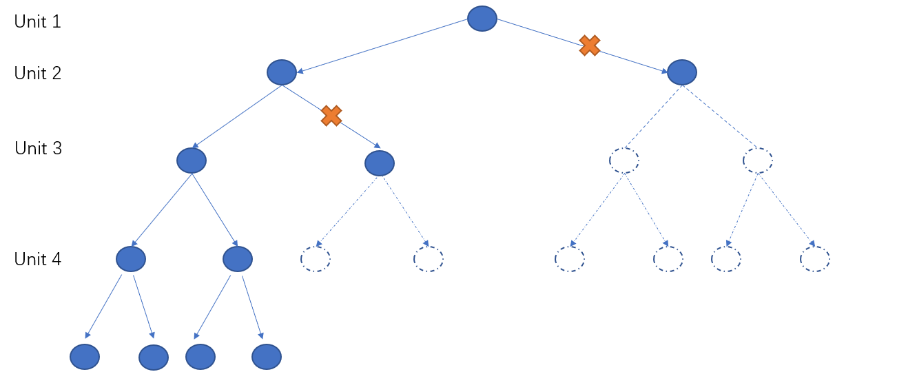
After arranging units in the order required by the latency, determine whether this unit needs to be assigned to the MEC for processing from the first unit. At this time, the tree diagram needs to be drawn, as shown in Fig. 3, use four units as an example. Starting from the vertex first unit, there are two paths, one (unit will be processed in MEC Server) and zero (unit will be processed in local device). If the unit latency caused by the path meets the requirements of this unit, this path will be maintained and the next level of judgment will be made. If the latency does not meet the requirements, then drop this path. Until finish the last task, and judgment whether the system latency is meet the requirement, if the answer is YES, keep this node, if not, drop this node, then all the feasible solutions can be obtained. Then, for getting the optimal solution, some other optimization to transmission power and clock frequency need to be done, and they will be introduced in the next few parts.

In the above situation, there is no correlation between units, the next section will introduce the situation with there are correlation between units. when , the duplicate units should be deleted, and then allocate the remaining units in the same way as said before. when , these units with a correlation degree of 0.5 need to be merged, that means merge them into a large task to carry out the process of task allocation(this allocation process is same as said before). If this large task is allocated to MEC server for processing, it will reduce the latency and energy consumption caused by communication, that because they use the same source information. If this large task is allocated to local device for processing, the energy consumption and the latency will not change.
III-D Clock Frequency Allocation
According to (6), if (the CPU cycle required to calculate the unit) not change, the smaller the value of , the lower energy consumption will take.
III-E Transmission Power Allocation
According to (3), (4), and (8) and use to represent the total transmission volume of all units that need to be transmitted to MEC, so the energy consumed for transmission becomes E1
| (18) |
. So, the monotonic interval of E1 with respect to , and take the value that minimizes E1 under conditions C1 to C5.
III-F Algorithm Flow
Use the maximum of the local device and maximum of local device to find all combinations that satisfy the conditions of C1-C5, and record them as , and then use the algorithms proposed before find the smallest value of energy consumption that can be achieved after optimization in , take the combination with the least energy consumption as the final result. Therefore, the optimal clock frequency, transmission power, and unit allocation method can be obtained.
IV Simulation results
In this section, we evaluate our proposed task-offloading algorithm with three state-of-the-art baselines through MATLAB based simulations. It is considered in our simulation, that system contains four users and a single MEC. Each user has different number of tasks, and different type of task has different size. Each user has its dedicated orthogonal channel to communicate to MEC.
The channel bandwidth is set to 20MHZ, and the channel conforms to the Rayleigh distribution. The SNR of the user terminal is set to 10dB, 20dB, 30dB, 40dB and 50dB in our simulations. The maximum computing rate in user’s device is cycles/s[10], and the maximum computing rate in MEC server is cycles/s [10], the size of each task is between 1-3M, and the number of processing revolutions they require is Between 1500-4500 cycles[10], and [8]. There are two latency requirements, which are 50ms and 100ms.


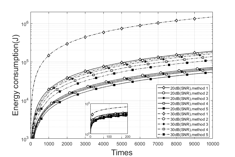
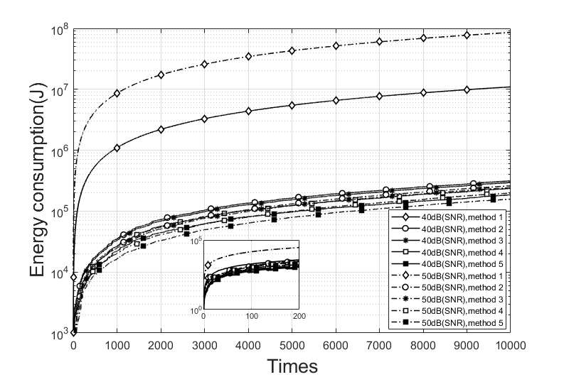
In the experiment, two proposed approaches simulated with the other three baselines. Method 1 (Baseline 1): the most primitive task offloading algorithm, without considering any transmission power and other optimizations. Method 2 (Baseline 2): Further optimize the processing frequency and transmission power based on the Method 1[6]. Method 3 (Baseline 3): Based on Method 1 and Method 2, consider the impact of split tasks on task offloading[4]. Method 4: Consider the relevance of task on time domain to reduce the amount of data. method 5: Base on Method 3, consider the correlation in time domain and in different tasks to reduce the amount of data.
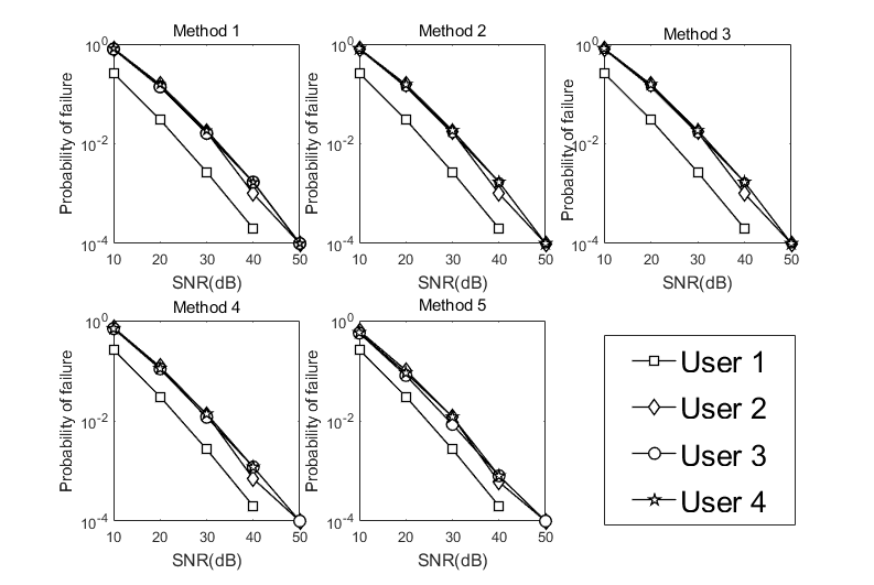
The Fig. 4(a) Fig. 4(b) show the energy consumption of the five different algorithms on the local device when the SNR on the user terminal are 20dB, 30dB, 40dB and 50dB respectively. In the same SNR, our proposed algorithms have better performs Fig. 5 shows the probability of task failure under different methods and SNR. From Fig. 4, and Fig. 5, with the same SNR, our proposed algorithms have better performs in energy saving and reliability, and as the increase of SNR, with the same method, the energy cost may increase too, this is because we record that the energy consumption of the failed tasks that can be known in the stage of decision making is zero. The larger the SNR, the more tasks that can be processed, so it will also cause more energy consumption.
V Conclusion
In this paper, it was studied how to improve the energy efficiency of local devices and reduce the latency in the process of task offloading. A novel task offloading algorithm has been proposed with the consideration of task correlation in both time domain and task domain to reduce the number of tasks to be transmitted. Moreover, a joint optimization has been studied for task allocation, transmission power and clock frequency. MATLAB based simulation results have demonstrated that the proposed task offloading algorithm can reduce the device energy consumption along various transmit power versus noise variance setup compare with the conventional one.

Acknowledgment
The work was supported in part by European Com- mission under the framework of the Horizon2020 5G-Drive project, and in part by 5G Innovation Centre (5GIC) HEFEC grant.
References
- [1] K. Choi et al., “Enhanced reliability of 7nm process technology featuring euv,” in Proc. 2019 Symposium on VLSI Technology, 2019, pp. T16–T17.
- [2] S. Wang, M. Zafer, and K. K. Leung, “Online placement of multi-component applications in edge computing environments,” IEEE Access, vol. 5, pp. 2514–2533, Feb. 2017.
- [3] L. K. Nandhini and S. Udhayakumar, “Service offloading of computationally intensive processes using hadoop image processing interface in private cloud,” in Proc. 8th International Conference on Advanced Computing (ICoAC), 2017, pp. 201–205.
- [4] J. Liu and Q. Zhang, “Offloading schemes in mobile edge computing for ultra-reliable low latency communications,” IEEE Access, vol. 6, pp. 12 825–12 837, Feb. 2018.
- [5] C. Liu et al., “Dynamic task offloading and resource allocation for ultra-reliable low-latency edge computing,” IEEE Trans. Commun., vol. 67, no. 6, pp. 4132–4150, Feb. 2019.
- [6] S. Guo et al., “Energy-efficient dynamic offloading and resource scheduling in mobile cloud computing,” in Proc. IEEE INFOCOM 2016 - The 35th Annual IEEE International Conference on Computer Communications, 2016, pp. 1–9.
- [7] K. Zhang et al., “Energy-efficient offloading for mobile edge computing in 5G heterogeneous networks,” IEEE Access, vol. 4, pp. 5896–5907, Aug. 2016.
- [8] A. P. Miettinen and J. K. Nurminen, “Energy efficiency of mobile clients in cloud computing,” HotCloud, vol. 10, no. 4-4, p. 19, Jun. 2010.
- [9] K. M. Bisheh, B. Zakeri, and S. M. H. Andargoli, “Correlation coefficient estimation for stochastic FDTD method,” in Proc. 7th International Symposium on Telecommunications (IST), 2014, pp. 234–238.
- [10] T. Q. Dinh, J. Tang, Q. D. La, and T. Q. S. Quek, “Offloading in mobile edge computing: Task allocation and computational frequency scaling,” IEEE Trans. Commun., vol. 65, no. 8, pp. 3571–3584, Apr. 2017.