Atomic Bose-Einstein condensate in twisted-bilayer optical lattices
Abstract
Observation of strong correlations and superconductivity in twisted-bilayer-graphene Cao2018-1 ; Cao2018-2 ; Yankowitz1059 ; Lu2019 has stimulated tremendous interest in fundamental and applied physics WANG2019100099 ; Andrei2020 ; Balents2020 ; Kennes2021 . In this system, the superposition of two twisted honeycomb lattices, generating a moir pattern, is the key to the observed flat electronic bands, slow electron velocity and large density of states PhysRevLett.99.256802 ; PhysRevB.81.161405 ; Bistritzer12233 ; PhysRevB.85.195458 . Extension of the twisted-bilayer system to new configurations is highly desired, which can open up exciting prospects to investigate twistronics beyond bilayer graphene. Here we demonstrate a quantum simulation of superfluid-to-Mott insulator transition in twisted-bilayer square lattices based on atomic Bose-Einstein condensates loaded into spin-dependent optical lattices. The lattices are made of two sets of laser beams that independently address atoms in different spin states, which form the synthetic dimension accommodating the two layers. The interlayer coupling is highly controllable by microwave field, which enables the occurrence of flat lowest band and novel correlated phases in the strong coupling limit. We directly observe the spatial moir pattern and the momentum diffraction, which confirm the presence of two forms of superfluid and a modified superfluid to insulator transition in twisted-bilayer lattices. Our scheme is generic and can be applied to different lattice geometries and for both boson and fermion systems. This opens up a new direction for exploring moir physics in ultracold atoms with highly controllable optical lattices.
pacs:
34.20.Cf, 67.85.Hj, 03.75.LmNovel band structures in lattice systems often lead to new material functions and discoveries. Twistronics, originating from the twisted-bilayer-graphene as a tunable experimental platform Cao2018-1 ; Cao2018-2 ; Yankowitz1059 ; Lu2019 ; WANG2019100099 ; Andrei2020 ; Balents2020 ; Kennes2021 has attracted broad attention in recent years and launched intensive theoretical research. Here overlaying two graphene layers with a small relative angle exhibit the rich phase diagram, such as the coexistence of unconventional superconductivity and correlated insulating phases Cao2018-2 ; Yankowitz1059 ; Lu2019 . In recent years, many examples of twisted-bilayer are discovered with remarkable physical properties not present in their untwisted counterparts. Recently, photonic moir lattices are explored for their capabilities in localizing and delocalizing light Wang2020 ; Huang2016 ; Fu2020 and twisted-bilayer materials for engineering the photonic dispersion Hu2020 .
Ultracold atoms in optical lattices constitute an ideal platform to simulate emerging many-body phenomena in condensed matter physics RevModPhys.80.885 ; Lewenstein-book ; Windpassinger_2013 . Different optical lattice geometries can be realized by interfering different sets of laser beams Soltan-Panahi2011 ; Wirth2011 ; Tarruell2012 ; PhysRevLett.108.045305 ; Taiee1500854 ; Gall2021 . In particular, a scheme of simulating twisted-bilayer lattice is recently proposed using two overlapping optical lattices PhysRevA.100.053604 ; PhysRevLett.126.103201 . Other schemes for simulating bilayer heterostructures have also been put forward Gra__2016 ; PhysRevLett.125.030504 . These schemes are based on coherent coupling between spin states of atoms, which simulates interlayer tunnelling along an artificial, synthetic dimension PhysRevLett.108.133001 ; PhysRevLett.112.043001 ; Ozawa2019 .
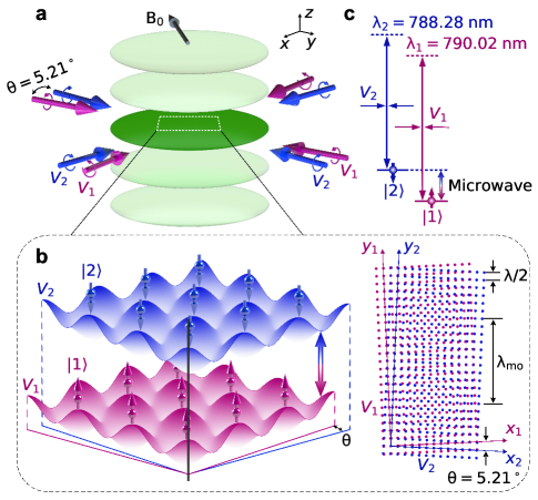
In this paper we demonstrate Bose-Einstein condensates (BEC) of Rubidium-87 (87Rb) atoms loaded into a pair of twisted-bilayer optical lattices. Two overlapping lattices and are formed by interfering laser beams at the specific “tune-out” wavelengths leblanc2007species ; arora2011tune ; Wen2021 and with proper polarizations such that atoms in spin state and state only experience the lattice potential and , respectively, see Fig. 1. Here and are the angular momentum and projection quantum numbers in the 87Rb ground state manifold. Each set of the laser beams forms a two-dimensional (2D) square lattice on the horizontal x-y plane and the twist of the two lattices is realized by orienting the beams of different wavelengths with a small relative angle . The sample is tightly confined in the vertical -direction such that the sample is in the quasi-2D regime (see Supplementary Material section I for details).
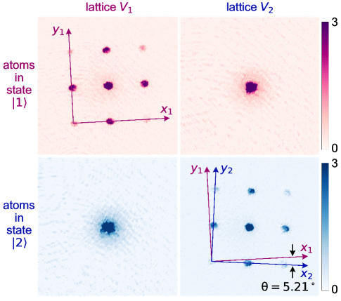
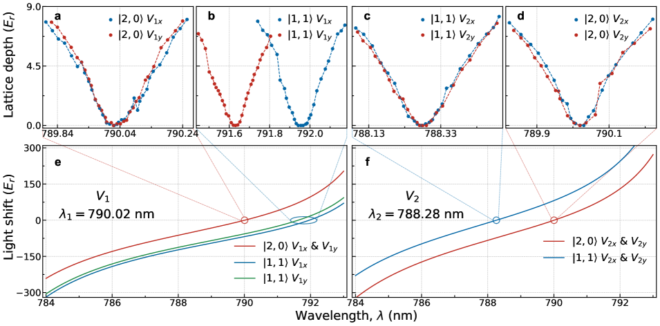
The two spin states of 87Rb atoms constitute the synthetic dimension that accommodates the two twisted layers of lattices and . To precisely determine the tune-out wavelengths and of the optical lattices and , we measure the diffraction of atoms by the optical lattices. The experimental sequence starts with an almost pure BEC in a crossed-beam dipole trap. The atoms are prepared in one of the two spin states and a short pulse of the lattice beams is applied. The lattice potential induces Bragg diffraction of atoms to high momentum states. After turning off the lattice beams, we image the diffracted atoms. The wavelengths of the lattice beams are finely adjusted to the “tune-out” wavelengths such that atoms in state are only diffracted by the lattice potential and not by the potential as shown in Fig. 2. Similarly atoms in state only experience the potential , but not . By eliminating the cross-talks, we determined the “tune-out” wavelengths to be nm and nm. Remarkably the lattice beams are circularly polarized to produce spatial intensity modulation such that the lattice potentials are attractive to atoms in both spin states (see Supplementary Material section II for details).

Experimentally intralayer hoppings and between lattice sites are controlled by the depth of the optical lattices and ; interlayer hopping , on the other hand, is independently induced by microwaves (MW) that couple the two spin states. Starting with atoms in state in the dipole trap, for example, the MW spectrum displays a single narrow peak when atoms are driven to state . By loading the atoms into the twisted-bilayer optical lattices, the spectrum displays multiple peaks. The peaks correspond to transitions from atoms in the ground band of lattice , which we label , to different Bloch bands of lattice , which we label , , and so on, see Figs. 3a and 3b. The peak locations agree with the calculated energies of the -, - and -bands in lattice . Remarkably, the multi-peak structure supports that atoms in different spin states are confined in different lattices. If atoms are loaded into a spin-independent lattice, only a single narrow peak shows up in the spectrum, which belongs to the to transition. This is because MW transitions between different Bloch bands are negligible in spin-independent lattices. In the twisted optical lattice, the transitions from -band of state to other bands of state are allowed. In the presence of the twisted bilayer lattices, the transitions are broadened since the two spin states experience different trap potentials, which induce fast dephasing. Moreover, the on-site interactions increase in deeper lattice potential, resulting in faster decay from high bands to lower bands and thus broader spectral lines. Our observation supports MW as a versatile and powerful tool to induce interlayer hopping between the two twisted layers in the synthetic (spin) dimension.
To quantify the interlayer hopping energy, we measure the time evolution of the population in state . We observe a coherent oscillation at detuning kHz, which corresponds to the transition from to , see Fig. 3c. The interlayer coupling strength can be determined from the oscillation frequencies. In our experiment, the coupling strength is tunable up to 1, which exceeds that in typical twisted-bilayer graphene systems. On the other hand, coupling to the -band leads to faster decay likely due to collisional relaxation to the lower -band, see Fig. 3d. In the following, we will focus on atoms in the twisted-bilayer optical lattices with MW-induced coupling between the -bands of the two layers.
A key signature of atoms in the twisted-bilayer optical lattice is the moir lattice with a period
| (1) |
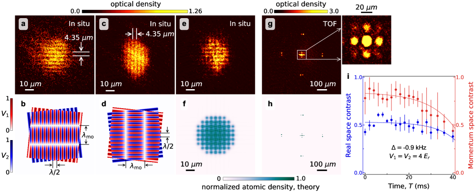
which, for the lattice constant nm and twist angle , amounts to m. The large moir period gives rise to a mini-Brillouin zone in the momentum space, which is expected to generate the flat bands and strongly correlated states Cao2018-1 ; Cao2018-2 ; Yankowitz1059 ; Lu2019 ; WANG2019100099 ; Andrei2020 ; Balents2020 ; Kennes2021 ; PhysRevLett.99.256802 ; PhysRevB.81.161405 ; Bistritzer12233 ; PhysRevB.85.195458 . Notably in-situ moir pattern is also observed in 1D lattices with two lattice constants PhysRevX.9.021001 . To identify the moir length scale in our system, we employ in situ absorption imaging to visualize the moir pattern, see Fig. 4. Here we first load the atoms in state into the lowest -band of lattice and then ramp up the MW field with detuning kHz to drive the transition from to . We then in situ image the atoms in state . Moir patterns in one and two dimensions are observed, and the moir period is measured to be 4.35 m consistent with expectation, see Figs. 4a-f. Note that the primary optical lattice spacing nm is indiscernible with our imaging optics.
We also examine the quantum state of atoms in the bilayer twisted lattices by analyzing their momentum space distribution. After loading a BEC into the bilayer lattice of 4 in the presence of resonant MW transition, we hold for some time and then perform the time-of-flight measurement, see Figs. 4g and 4h. Two sets of diffractions manifest, which correspond to the primary lattice momentum and the much smaller moir momentum . The high contrast of both sets of diffraction pattern suggests that the atoms remain in the superfluid phase with phase coherence extending beyond the moir length scale. In particular, the contrasts of the moir pattern in real and momentum space persist over 40 ms, see Fig. 4i, from which we conclude that the atoms maintain in the superfluid phase in the twisted-bilayer lattices.
Theoretically, depending on the twist angle , the superimposed twisted-bilayer lattice can yield either a periodic potential with supercells that supports a delocalized ground state or a quasi-periodic one that supports a localized ground state in the absence of interactions. In fact, only specific twist angles give rise to periodic lattice potentials. For square lattices, the twist angles that lead to commensurate superlattice should satisfy , where and are integers Wang2020 . The twist angle used in our work is close to the commensurate angle , and the period of the supercell is given by (see Supplementary Material section III for details). While our twist angle does not exactly match the commensurate angle , the small difference can not be distinguished in a finite size sample due to repulsive interactions (see Supplementary Material section IV for details). In particular, the spatial moir period remains a clear observable in our experiment because of the finite chemical potential of our atomic superfluid. The persistence of the spatial and momentum periodicity of the sample in the twisted-bilayer lattice supports the superfluid as the ground state of the system.
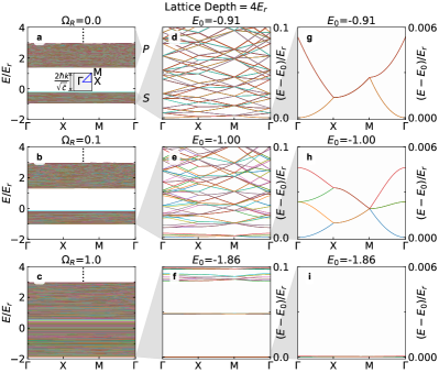
Compared with electronic materials, where the flat band is investigated frequently near the Fermi surface, we can also explore flatband physics with bosons condensed in the lowest band. In our system, when interlayer coupling increases, the long-wavelength moir potential becomes deeper, so atoms in the lowest band are isolated at a larger spatial scale (moir wavelength), which flattens the ground band and enhances the localization of the atoms. In the large interlayer coupling limit, the system can be regarded as a single-layer (single-component) experiencing a twisted optical lattice (see Supplementary Material section III for details). The single-layer system with a twisted optical lattice admits a flatband structure in the ground band, which has also been studied experimentally in photonic systems Wang2020 ; Huang2016 ; Fu2020 . The easily-tuned intra- and interlayer couplings in our system offer the added advantages of seeking novel quantum phases and phase transitions with cold atoms.
By varying the depth of optical lattices and interlayer coupling, we find several distinct quantum phases, including superfluid (SF), superfluid with only short-range coherence (SF-II), Mott Insulator (MI) and insulator (I), (see Fig. 5a and Supplementary Material section IV). These phases can be distinguished by the phase coherence and real-space density correlations. Remarkably the SF-II phase emerges with finite interlayer coupling around the transition from a regular SF to an insulator. The spatial range of phase coherence is the key to distinguishing the two SF phases: while an SF supports long-range phase coherence PhysRevA.72.053606 , the SF-II phase maintains the coherence only up to the moir length scale. In addition, the SF-II phase supports the moir pattern in the real-space. Theoretically, SF-II is the phase with superfluid domains embedded in a gapped insulator, induced by the interlayer coupling. Finally, the insulator phases I and MI can be identified by the disappearance of spatial coherence at all scales and integer fillings of all the sites. While the MI has uniform atom density with weak interlayer coupling, the I phase features moir pattern due to stronger interlayer coupling.

In the experiment, we measure the phase coherence from the momentum-space diffraction peaks in the TOF images and directly probe the moir pattern by in situ imaging following the measurement method as shown in Fig. 4. The measurement of the phase boundaries is shown in Fig. 5a. We employ three independent paths to study these phases. Path I, we fix the interlayer coupling strength at a small value and increase the lattice depth. The phase transition from SF to MI and across SF-II is shown in the time-of-flight images, see Fig. 5b. Here the diffraction peaks at the moir momenta disappear first before the disappearance of the primary lattice. The intermediate regime indicates the SF-II phase, where the moir-scale long-range correlation is destroyed while a short-range coherence remains, at the same time, the density correlations of moir pattern appears in the real-space. Path II, we fix lattice depth in the SF region and increase the interlayer coupling. The diffraction peaks at the moir momenta persist with high contrasts. However, in Path III, when the depth of optical lattices is fixed at the MI region and the interlayer coupling increases, the visibility at the moir momenta presents the threshold behavior and emerges at , see Fig. 5c. These observations are qualitatively consistent with the theoretical expectation and demonstrate that the interlayer coupling can induce a reentrant transition from MI to SF across SF-II. One may understand such rich transitions from the fact that the interplay between the interlayer coupling and interactions tends to localize the bosons, primarily in the moir length scale.
This work provides a preliminary physical insight into the quantum phase transition between SF and SF-II ( MI and SF-II or MI and I) and offers the possibility to study the complex phases due to the presence of quasi-disorder induced by large interlayer coupling and strong interaction, such as Bose glass insulator, resembling that in disordered bosonic systems PhysRevB.40.546 ; PhysRevLett.67.2307 ; PhysRevB.53.2691 . These complex phases are worth further investigating in the future.
The present work focuses on the realization and the ground state properties of atoms in the twisted-bilayer optical square lattice. Our success in loading a superfluid into the bilayer lattice demonstrates a new versatile platform to explore moir physics and the associated superfluidity in a quantum many-body system. Beyond the tunable twist angle, the cold atom platform offers remarkable controls such as different lattice depths and interlayer coupling in different layers.
Furthermore, the twisted-bilayer square lattice closely connects to the physics of heterostructures of twisted atomically thin semiconductors PhysRevResearch.1.033076 ; Kennes2020 ; Kennes2021 . At the same time, our experiment can in principle be extended to multi-layer lattice where the interlayer couplings can be independently induced by MW and radio-frequencies. Replacing the MW by optical Raman transitions, the interlayer coupling can be spatial dependence, which can support topological ground states. Finally, our optical lattice scheme can be applied to confine fermionic atoms in bilayer hexagonal lattice, which faithfully simulates electrons in a bilayer graphene, and may offer insight into the emergence of superconductivity in the strongly correlated, flatband regime.
DATA AVAILABILITY
All data generated or analysed during this study are included in this published article. Additional data are also available from the corresponding authors upon reasonable request.
Acknowledgements.
This research is supported by Innovation Program for Quantum Science and Technology (Grant No. 2021ZD0302003), National Key Research and Development Program of China (2016YFA0301602, 2018YFA0307601, 2022YFA1404101), NSFC (Grant No. 12034011, 12022406, 11804203), the Fund for Shanxi “1331 Project” Key Subjects Construction and Tencent (Xplorer Prize). CC acknowledges support by the National Science Foundation (Grant No. PHY-2103542), and the Army Research Office STIR (Grant W911NF2110108).Author contributions
J.Z. conceived the idea and performed the experimental designs. L.W., Z.M., F.L., K.W., P.W. and J.Z. performed the experiments. C.C., Z.M., L.W., F.L., W.H. and J.Z. analysed the data and all authors discussed the results. W.H., C.G. and J.Z. performed the simulation. Z.M. plotted the figures. J.Z. and C.C. wrote the manuscript. All authors interpreted the results and reviewed the manuscript. J.Z. designed and supervised the project.
Competing interests
The authors declare no competing financial interests.
References
- (1) Cao, Y. et al. Correlated insulator behaviour at half-filling in magic-angle graphene superlattices. Nature 556, 80–84 (2018).
- (2) Cao, Y. et al. Unconventional superconductivity in magic-angle graphene superlattices. Nature 556, 43–50 (2018).
- (3) Yankowitz, M. et al. Tuning superconductivity in twisted bilayer graphene 363, 1059–1064 (2019).
- (4) Lu, X. et al. Superconductors, orbital magnets and correlated states in magic-angle bilayer graphene. Nature 574, 653–657 (2019).
- (5) Wang, J., Mu, X., Wang, L. & Sun, M. Properties and applications of new superlattice: twisted bilayer graphene. Mater. Today Phys. 9, 100099 (2019).
- (6) Andrei, E. Y. & MacDonald, A. H. Graphene bilayers with a twist. Nat. Mater. 19, 1265–1275 (2020).
- (7) Balents, L., Dean, C. R., Efetov, D. K. & Young, A. F. Superconductivity and strong correlations in moir flat bands. Nat. Phys. 16, 725–733 (2020).
- (8) Kennes, D. M. et al. Moir heterostructures as a condensed-matter quantum simulator. Nat. Phys. 17, 155–163 (2021).
- (9) Lopes dos Santos, J. M. B., Peres, N. M. R. & Castro Neto, A. H. Graphene bilayer with a twist: electronic structure. Phys. Rev. Lett. 99, 256802 (2007).
- (10) Mele, E. J. Commensuration and interlayer coherence in twisted bilayer graphene. Phys. Rev. B 81, 161405 (2010).
- (11) Bistritzer, R. & MacDonald, A. H. Moiré bands in twisted double-layer graphene 108, 12233–12237 (2011).
- (12) Moon, P. & Koshino, M. Energy spectrum and quantum hall effect in twisted bilayer graphene. Phys. Rev. B 85, 195458 (2012).
- (13) Wang, P. et al. Localization and delocalization of light in photonic moiré lattices. Nature 577, 42–46 (2020).
- (14) Huang, C. et al. Localization-delocalization wavepacket transition in pythagorean aperiodic potentials. Sci. Rep. 6, 32546 (2016).
- (15) Fu, Q. et al. Optical soliton formation controlled by angle twisting in photonic moiré lattices. Nat. Photonics 14, 663–668 (2020).
- (16) Hu, G. et al. Topological polaritons and photonic magic angles in twisted -moo3 bilayers. Nature 582, 209–213 (2020).
- (17) Bloch, I., Dalibard, J. & Zwerger, W. Many-body physics with ultracold gases. Rev. Mod. Phys. 80, 885–964 (2008).
- (18) Lewenstein, M., Sanpera, A. & Ahufinger, V. Ultracold atoms in optical lattices: simulating quantum many-body systems (Oxford University Press, 2012).
- (19) Windpassinger, P. & Sengstock, K. Engineering novel optical lattices. Rep. Prog. Phys. 76, 086401 (2013).
- (20) Soltan-Panahi, P. et al. Multi-component quantum gases in spin-dependent hexagonal lattices. Nat. Phys. 7, 434–440 (2011).
- (21) Wirth, G., lschlger, M. & Hemmerich, A. Evidence for orbital superfluidity in the p-band of a bipartite optical square lattice. Nat. Phys. 7, 147–153 (2011).
- (22) Tarruell, L., Greif, D., Uehlinger, T., Jotzu, G. & Esslinger, T. Creating, moving and merging dirac points with a fermi gas in a tunable honeycomb lattice. Nature 483, 302–305 (2012).
- (23) Jo, G.-B. et al. Ultracold atoms in a tunable optical kagome lattice. Phys. Rev. Lett. 108, 045305 (2012).
- (24) Taie, S. et al. Coherent driving and freezing of bosonic matter wave in an optical lieb lattice 1, e1500854 (2015).
- (25) Gall, M., Wurz, N., Samland, J., Chan, C. F. & Khl, M. Competing magnetic orders in a bilayer hubbard model with ultracold atoms. Nature 589, 40 (2021).
- (26) González-Tudela, A. & Cirac, J. I. Cold atoms in twisted-bilayer optical potentials. Phys. Rev. A 100, 053604 (2019).
- (27) Luo, X.-W. & Zhang, C. Spin-twisted optical lattices: tunable flat bands and larkin-ovchinnikov superfluids. Phys. Rev. Lett. 126, 103201 (2021).
- (28) Graß, T., Chhajlany, R. W., Tarruell, L., Pellegrini, V. & Lewenstein, M. Proximity effects in cold atom artificial graphene. 2D Mater. 4, 015039 (2016).
- (29) Salamon, T. et al. Simulating twistronics without a twist. Phys. Rev. Lett. 125, 030504 (2020).
- (30) Boada, O., Celi, A., Latorre, J. I. & Lewenstein, M. Quantum simulation of an extra dimension. Phys. Rev. Lett. 108, 133001 (2012).
- (31) Celi, A. et al. Synthetic gauge fields in synthetic dimensions. Phys. Rev. Lett. 112, 043001 (2014).
- (32) Ozawa, T. & Price, H. M. Topological quantum matter in synthetic dimensions. Nat. Rev. Phys. 1, 349–357 (2019).
- (33) LeBlanc, L. J. & Thywissen, J. H. Species-specific optical lattices. Phys. Rev. A 75, 053612 (2007).
- (34) Arora, B., Safronova, M. S. & Clark, C. W. Tune-out wavelengths of alkali-metal atoms and their applications. Phys. Rev. A 84, 043401 (2011).
- (35) Wen, K. et al. Experimental study of tune-out wavelengths for spin-dependent optical lattice in 87rb bose-einstein condensation. J. Opt. Soc. Am. B 38, 3269 (2021).
- (36) McDonald, M., Trisnadi, J., Yao, K.-X. & Chin, C. Superresolution microscopy of cold atoms in an optical lattice. Phys. Rev. X 9, 021001 (2019).
- (37) Gerbier, F. et al. Interference pattern and visibility of a mott insulator. Phys. Rev. A 72, 053606 (2005).
- (38) Fisher, M. P. A., Weichman, P. B., Grinstein, G. & Fisher, D. S. Boson localization and the superfluid-insulator transition. Phys. Rev. B 40, 546–570 (1989).
- (39) Krauth, W., Trivedi, N. & Ceperley, D. Superfluid-insulator transition in disordered boson systems. Phys. Rev. Lett. 67, 2307–2310 (1991).
- (40) Freericks, J. K. & Monien, H. Strong-coupling expansions for the pure and disordered bose-hubbard model. Phys. Rev. B 53, 2691–2700 (1996).
- (41) Kariyado, T. & Vishwanath, A. Flat band in twisted bilayer bravais lattices. Phys. Rev. Res. 1, 033076 (2019).
- (42) Kennes, D. M., Xian, L., Claassen, M. & Rubio, A. One-dimensional flat bands in twisted bilayer germanium selenide. Nat. Commun. 11, 31124 (2020).
Supplementary Material
I. Experimental setup
In our experiment, the ultracold 87Rb atoms in the state are prepared in the crossed optical dipole trap Xiong:10 (44). Forced evaporation in the optical trap creates the BEC with up to atoms. The atoms can be transferred to the state via a rapid adiabatic passage induced by microwave transition. To load the atoms into the 2D trap, a 532 nm laser beam is deflected by an acousto-optic deflector (AOD) and then split into two beams with variable spacing adjusted by the AOD. The two beams are focused onto the atoms with a 150 mm aspherical lens. These beams interfere to form a standing wave in the vertical direction with variable separation (Accordion lattice). This separation can be varied from 12 down to 3 . The advantage of variable spacing is that we can load a 3D shaped cloud into a single layer of the 2D pancakes at maximum separation and then compress the pancake adiabatically to reach a deep 2D regime. The maximum vertical confinement can reach more than 20 kHz and we optimize it at 1 kHz to observe moir pattern and superfluid of ultracold atoms.
The twisted-bilayer optical lattices are created by two sets of 2D square lattice and . A twisted angle of is set between the two lattice potentials, namely, , . The optical lattices and are derived from two CW Ti:Sapphire single frequency lasers (M Squared lasers SolsTiS and Coherent MBR-110) respectively. Two lattice beams and of are frequency-shifted +80 MHz and +95 MHz by two single-pass acousto-optic modulators (AOMs), respectively. The same applies to the two lattice beams and of lattice . The four lattice beams are coupled into polarization-maintaining single-mode fibers in order to improve the stability of the beam pointing and achieve better beam-profile quality. After the fibers, each lattice beam is focused by a lens and retroreflected by a concave mirror. In order to generate the vector light shift, we use the same circular polarization for two lattice beams to produce spatial intensity modulation. In the experiment, we can determine and calibrate this angle by measuring the intersection angle between two lasers and the moir period from the in situ images. The estimated uncertainty of the two methods is about 0.05∘.
We use the MW field to couple the two spin states for manipulating the interlayer coupling. The 6.8 GHz MW signal is amplified by a 10 W solid state amplifier (Kuhne Electronic, KU PA 640720-10A). We place a circulator on the output of the amplifier to reduce reflected power coming back to the amplifier. The MW is emitted out to the atoms by a sawed-off waveguide, which is placed outside of the high vacuum glass cell. We use MW cables to transfer MW from the amplifier to the waveguide. With this MW power amplifier, we can reach the maximum interlayer coupling strength of about 1.0. It is feasible to increase the interlayer coupling strength to about several by using an available higher power amplifier.
Our image system consists of an objective with a numerical aperture of NA=0.69, working distance of 11 mm and effective focal length of 18 mm. A 900 mm lens after the objective leads to a magnification of 50 for in situ imaging with an EMCCD (Andor iXon Ultra 897). We also employ a 200 mm (400 mm) lens after the objective leads to a magnification of 11 (22) for the time-of-flight absorption imaging with 18 ms. The atoms are detected by state-selective absorptive imaging. Since we choose two ground hyperfine Zeeman states of 87Rb of the , and of the hyperfine manifold as the two internal spin states, we can fully resolve the population in each individual state. For state, a 50 s long imaging pulse of resonant light on the D2 cycling transition is used to detect the atoms. In order to detect state, a resonant light pulse on the cycling transition is firstly used to remove the atoms and then a 50 s long imaging pulse of resonant light on the is applied at the same time with a repump light (resonant light ) to detect the atoms.
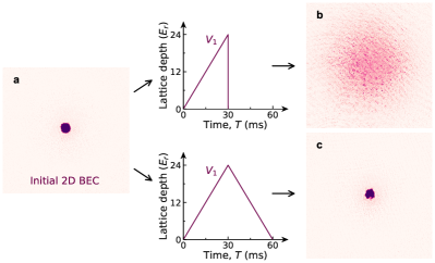
When studying the superfluid-to-Mott insulator transition, we use the standard method of interference pattern contrast (visibility) to reveal this transition PhysRevA.72.053606 ; Greiner2002 (45). We first load the atoms in state into the lowest -band of lattice by ramping up and simultaneously with 30 ms, and then ramp up the MW field with 10 ms to drive the transition from to . The atoms are detected by state-selective absorptive imaging with time-of-flight of 18 ms after switching off all lattices and trapping light. In experiment, we first check that BEC is still kept (see Fig. S1) as ramp up the lattice (or ) to the higher lattice depth than and then ramp down again, which makes sure to perform the phase transition from SF to MI successfully for the lattice V1 (or V2). When adding the interlayer coupling between two spin states, and at the same time a quasi-disorder is introduced, there are two more mechanics to make the system not completely reversible. One is the finite coherent time between two spin states. When the system is prepared initially in the spin down, the system will become the spin mixture after the interlayer coupling is ramped back down. We define this process as irreversibility. The other is that adiabaticity is broken down by a quasi-period or disordered lattice, which induces not to completely remain in the zero-momentum state after ramping the lattices back down.
II. Tune-out wavelength for twisted-bilayer optical lattices
AC Stark shift, or light shift is a light-induced change of energy level. For alkali-metal atoms, the total ac Stark shift can be expressed in the irreducible components (including scalar, vector, tensor components) of the polarizability steck2007quantum (46):
| (2) | ||||
where is the total atomic angular momentum, is the magnetic quantum number, is the laser frequency, is the laser field intensity, is light ellipticity, and are unit vectors along the light wave-vector and magnetic field quantization axis respectively, is the intersection angle between the linearly polarized component of light field and . This formula comes from the perturbation expansion. Note that the range of values of light ellipticity is , denotes left and right circular polarization. are the scalar, vector, and tensor polarizability, respectively. Scalar shift is spin independent. Vector shift acts like an effective magnetic field to generate the linear Zeeman splitting (light shift proportional to ), which depends on the ellipticity of the light and the intersection angle between the laser beam wave vector and magnetic field quantization axis . So there are two methods to control the vector shift, rotating bias magnetic field and changing light polarization. Tensor part is derived from the linearly polarized light, and acts as an effective dc electric field.
For the first excited state of alkali-metal atoms, the fine structure interaction induces the spectral lines of the D1 () and D2 () lines. The coefficients of the scalar, vector and tensor shifts of the ground states of 87Rb atoms in Eq. 2 are given by
| (3) | ||||
where is the decay rate of the excited state for line, is the effective frequency, , is the frequency detuning of the laser. Therefore, according to Eq. 3 we only consider the scalar and vector shift in this work. We employ tune-out wavelength for spin-dependent optical lattice, in which ac Stark shifts cancel. Two internal spin states have different tune-out wavelengths when the contributions of both the scalar and vector shifts are included Wen2021 .
We choose two ground hyperfine Zeeman states of 87Rb of the , and of the hyperfine manifold as the two internal spin states. A bias magnetic field with 10 Gauss is applied along the diagonal line of the square lattice . We scan the wavelength of the optical lattice beams to determine the tune-out wavelength precisely, as shown in Fig. S2. The tune-out wavelength for state is determined at 788.28 nm with circular polarization as shown in Fig. S2(c), which balances the contribution of the scalar and vector shift. Thus we choose this wavelength for the lattice . Note that the tune-out wavelength for state is sensitive to the intersection angle between the laser beam wave vector and magnetic field quantization axis, which requires a careful alignment of the bias magnetic field carefully. The spin state only experiences the square lattice with the red-detuning AC stark shift (which is only from scalar shift) as shown in Fig. S2(d) and (f), in contrast, the spin state experiences no shift.
On the other hand, there is only the contribution of the scalar shift for the spin state , the tune-out wavelength for state is 790.02 nm as shown in Fig. S2(a), which is well known and studied experimentally arora2011tune ; Wen2021 . We choose this tune-out wavelength of 790.02 nm with circular polarization as the wavelength of the lattice . Thus the spin state experiences the square lattice with the red-detuned AC stark shift. In contrast, the spin state see zero light shift. Note that the tune-out wavelength for state is insensitive to the intersection angle between the laser beam wave vector and magnetic field quantization axis. The spin state , however, has a different lattice depth in two orthogonal directions of the lattice respectively, and feels the lattice with the red-detuning AC stark shift (which is only from vector shift at the wavelength of 790.02 nm) as shown in Fig. S2(b) and (e).
Moir superlattice can be generated by a small difference in lattice constant or orientation. Since two different wavelengths are used for twisted-bilayer lattices in this work, there is a large-period superlattice with m, much larger than the size of atomic cloud. Therefore, we can adjust the retroreflected concave mirror to load atoms into the lower potential well of the long-period superlattice and neglect the influence on the measurement of moir pattern. In the future, we can correct this effect of two different wavelengths by using a slight angle lattice beam for to ensure the same lattice constant for two lattice potentials.
III. Band structures and flat band
For square lattices, the commensurate angles satisfy , where and are integers. An equivalent condition is and , which can be defined by Pythagorean triples (, where are positive integers) Wang2020 . The relationship between (,) and is when and when . For the commensurate optical lattice, the period of its supercell is given by when and when .
Here, we choose the band structure of the commensurate optical lattice with the commensurate angle as an approximation of the experimental case. If getting a better approximation of band structure for the experimental case, we can choose the larger supercell to calculate the energy band structure, whose commensurate angle is closer to the experimental case. The band structure of the commensurate optical lattice can be obtained by solving the stationary Schrödinger equation, , with the Bloch function, . Here the Hamiltonian is given as
| (4) |
is a periodic function with the same periodicity as the coupled lattice. The spin-dependent square optical lattice with a twist angle can be described by the potentials
| (5a) | |||
| (5b) | |||
where is the wave number of lasers for the lattice and describes the lattice depth. In numerics we first discretize the unit supercell of area in real space ( is the largest value in the Pythagorean triple) into grids, and then diagonalize the effective Hamiltonian for . As shown in Fig. S3, the band structure approaches the flat band when increasing the interlayer coupling.
Since our system allows for flexible control of the interlayer couplings, the flatband in the lowest energy band can be realized. The Hamiltonian Eq. 4 can be formally diagonalized as
| (6) |
where
| (7) |
with , and . In the large interlayer coupling limit, , the low-energy band structure is encoded in the effective Hamiltonian in the lower-right block, which can be further approximated as
| (8) |
or in a more rough way
| (9) |
The approximated effective Hamiltonians correspond to some effective lattices for a single-layer (single-component) system, separately, for Eq. 8, and for Eq. 9, with certain global energy shift. Specifically Eq. 9 implies that the system becomes the single-layer (single-component) experiencing a twisted optical lattice.
When increasing the interlayer coupling into the strong region, the long-wavelength moir potential becomes deeper, so atoms in the lowest band are isolated at a larger spatial scale (moir wavelength), which enhances the wavefunction localization and contributes to the creating of flatband. The single-layer system with a twisted optical lattice (approximation at the strong interlayer coupling limit) admits a flatband structure in the lowest band, which has been studied experimentally in photonic system Wang2020 ; Huang2016 ; Fu2020 . The moir flat bands have several advantages. First, the flat bands quench kinetic energy scales (wavefunction localization), thereby drastically enhance the role of interactions and amplify the effects of interactions. Second, the moir superlattice leads to the emergence of minibands within a reduced Brillouin zone. The small Brillouin zone means that low atomic densities are sufficient for full filling or depletion of the superlattice bands, which is easily controlled in experiment.
IV. Theoretical calculation of the modified superfluid to insulator transition
In the mean-field approximation, the system for the superfluid phase can be well described by the coupled Gross-Pitaevskii (GP) equations
| (10) | |||
| (11) |
where the MW detuning is and the wave function is normalized as , with the total atom number. The strong confinement along the axis gives rise to the quasi-2D interaction strengths represented by a reduction coefficient multiplied by , where defines the characteristic length along the z axis, and is the 3D s-wave scattering length. In the experiment, the trapping frequency , and the scattering length for the 87Rb atoms is about with the Bohr radius. This implies that even though the system is thermodynamically 2D, the collisions still keep their 3D character with . Considering the similarity in scattering lengths , and for the 87Rb atoms, in the calculation we focus on the SU(2) symmetric interaction with . In addition to the intercomponent atomic interaction, the two components are also coupled by a microwave pulse, which causes Rabi oscillations with frequency .
By using the imaginary time evolution method, one can solve the GP equations numerically for the ground states in the harmonic trap. Theoretically the non-commensurate twist angle should be a localized single particle ground state while the commensurate angle gives rise to extended ground states in the absence of interactions. Experimentally the interatomic interaction is dominant, and always leads to extended many-body states with the aperiodic and periodic bilayer lattices becoming almost indistinguishable.
The phase transition from superfluid to Mott-insulator can be well described by the Bose-Hubbard model in the tight-binding approximation. For simplicity we consider the interlayer coupling as a quasi-periodically perturbed potential, which leads to a site-dependent energy offset
| (12) |
where the subindex and label the position of the -th site in the two-dimensional space. The tight-binding Hamiltonian for one layer then is given by
| (13) |
where the first term describes the nearest-neighbor tunnelling with and being the creation and annihilation operators, and the second term represents the on-site interaction. The hopping amplitude is considered to be site-independent for weak interlayer coupling and can be estimated by . The local repulsion depends on the depth of the optical lattice, and is given by Zwerger_2003 (47). The chemical potential controls the average number of atoms in the moiré lattice.
The mean-field phase diagram (Fig. 5a in the Main text) can be mapped by using the Gutzwiller method, which expands the local state at site in the Fock basis PhysRevB.45.3137 (48, 49). When the interlayer coupling , the system is reduced to the standard Bose-Hubbard model PhysRevB.40.546 , which includes two phases, the superfluid phase and the Mott insulator phase PhysRevLett.81.3108 (50, 45). While the superfluid phase is identified by the superfluid order parameter and an arbitrary filling of the atoms on the site, the Mott insulator phase emerges with an integer number of atoms per site with . When the interlayer coupling , the persistent coherence of the moir and primary lattice length scale, as well as density distribution in real space can be used to distinguish the phases, which is determined by the order parameter and the filling of the atoms on the site as shown in Fig. S4. The chemical potential is considered in this calculation.
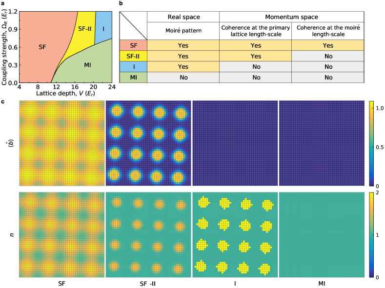
Phase diagram with zero temperature and the homogeneous system is predicted theoretically as shown in Fig. S4a, in which four phases of superfluid (SF), superfluid II (SF-II), Mott insulator (MI), and insulator (I) are included. The SF-II phase is a state with superfluid domains embedded in a gapped insulate state, which is caused by interlayer coupling. So SF-II phase can be identified by checking the disappearance of the moir-scale long-range correlation with vanishing moir lattice momentum but the remaining of short-range coherence with residual primary lattice momentum. At the same time, the SF-II phase supports the moir pattern in the real-space. Since MI is an incompressible insulator for integer filling factor with a gap for particle–hole excitations induced by the onsite interaction , the moir pattern in the real-space appears only when the interlayer coupling strength is larger than to break this gap. Therefore, the I phase supports the moir pattern in the real-space and no spatial coherence at all scales, which approaches the MI phase without the moir pattern in the real-space in the limit of weak interlayer coupling. Here, the phase transition between the SF to the MI phase should have an intermediate phase SF-II. Obviously, the coherence is lost almost simultaneously in all length scales at the critical point at very weak interlayer coupling only for zero temperature as shown in Fig. 5a. In contrast, at finite temperature, the thermodynamic quantities behave smoothly near the critical point and the long-range moir coherence is lost more before the short-range primary lattice length. Therefore, there exists an SF-MI critical regime, which seems likely to be a thermodynamic phase and is not predicted theoretically at zero temperature. The SF-MI critical regime has the same coherence as SF-II without the moir-scale long-range correlation but with the short-range coherence. However, the SF-MI critical regime does not support the moir pattern in the real-space which is distinguished from SF-II. In fact, the insulator phase presents special characteristics due to the strong interaction and quasi-disorder induced by the larger interlayer coupling, such as similar to Bose glass insulator from the model of disordered strongly interacting bosonic system PhysRevB.40.546 ; PhysRevLett.67.2307 ; PhysRevB.53.2691 .
References
- (1) Xiong, D., Wang, P., Fu, Z., Chai, S. Zhang, J. Evaporative cooling of 87Rb atoms into Bose-Einstein condensate in an optical dipole trap. Chin. Opt. Lett. 8, 627–629 (2010).
- (2) Greiner, M., Mandel, O., Esslinger, T., Hnsch, T. W. Bloch, I. Quantum phase transition from a superfluid to a Mott insulator in a gas of ultracold atoms. Nature 415, 39 (2002).
- (3) Steck, D. A. Quantum and atom optics (2007).
- (4) Zwerger, W. Mott Hubbard transition of cold atoms in optical lattices. J. Opt. B: Quantum Semiclass. Opt. 5, S9–S16 (2003).
- (5) Krauth, W., Caffarel, M. Bouchaud, J.-P. Gutzwiller wave function for a model of strongly interacting bosons. Phys. Rev. B 45, 3137–3140 (1992).
- (6) Sheshadri, K., Krishnamurthy, H. R., Pandit, R. Ramakrishnan, T. V. Superfluid and Insulating Phases in an Interacting-Boson Model: Mean-Field Theory and the RPA. Europhys. Lett. 22, 257–263 (1993).
- (7) Jaksch, D., Bruder, C., Cirac, J. I., Gardiner, C. W. Zoller, P. Cold Bosonic Atoms in Optical Lattices. Phys. Rev. Lett. 81, 3108–3111 (1998).