Effects of collisional ion orbit loss on neoclassical tokamak radial electric fields
Abstract
Ion orbit loss is considered important for generating the radially inward electric field in a tokamak edge plasma. In particular, this effect is emphasized in diverted tokamaks with a magnetic X point. In neoclassical equilibria, Coulomb collisions can scatter ions onto loss orbits and generate a radially outward current, which in steady state is balanced by the radially inward current from viscosity. To quantitatively measure this loss-orbit current in an edge pedestal, an ion-orbit-flux diagnostic has been implemented in the axisymmetric version of the gyrokinetic particle-in-cell code XGC. As the first application of this diagnostic, a neoclassical DIII-D H-mode plasma is studied using gyrokinetic ions and adiabatic electrons. The validity of the diagnostic is demonstrated by studying the collisional relaxation of in the core. After this demonstration, the loss-orbit current is numerically measured in the edge pedestal in quasisteady state. In this plasma, it is found that the radial electric force on ions from approximately balances the ion radial pressure gradient in the edge pedestal, with the radial force from the plasma flow term being a minor component. The effect of orbit loss on is found to be only mild. How ion orbit loss will affect in the full-current ITER plasma pedestal is left as a subsequent study topic.
1 Introduction
In tokamaks, the ion orbits have finite excursion widths across magnetic flux surfaces, so the ions at the plasma edge can move across the last closed flux surface (LCFS) and enter the scrape-off-layer (SOL) region. While some ions will cross the LCFS again and return to the confined region, others may hit the wall. This effect is known as ion orbit loss, and is considered important for the modeling of plasma properties at the edge, such as the radial electric field and the toroidal rotation. Ion orbit loss has been emphasized in diverted tokamaks with a magnetic X point, in which the orbit length from the LCFS to the divertor plates changes with the toroidal-magnetic-field direction, and the modified process is referred to as X-point ion orbit loss [1, 2, 3, 4]. Ion orbit loss has been studied by many authors [1, 2, 3, 4, 5, 6, 7, 8, 9, 10, 11, 12, 13, 14], either in limiter- or divertor-tokamak geometry. It is sometimes assumed that the ion distribution function is empty to the lowest order in the loss-orbit velocity space but is Maxwellian in other parts of the velocity space [15, 16, 17]. However, this assumed distribution function is known to be inaccurate due to effects such as collisional and turbulent scattering into and out of the loss-orbit portion of the velocity space [18]. The X-point ion-orbit-loss theory emphasizes the difference between the “forward-” configuration when the magnetic drift points towards the X point, and the “backward-” configuration when the magnetic drift points away from the X point [1, 2, 3]. Quantitative kinetic evaluation of the effect of ion orbit loss on , including changes in its effect between the two configurations, are desirable.
In this paper, we study the quantitative effects of ion gyrocenter orbit loss on neoclassical using an ion gyrokinetic neoclassical code with adiabatic electrons, in which the the total ion radial current must be equal to zero. Here, is the ion polarization current associated with the time evolution of , and is the ion gyrocenter current. In a steady-state edge plasma, both and should separately vanish; namely, and . Here, is the ion gyrocenter current induced by neoclassical viscosity and is the ion gyrocenter current induced by steady-state collisional scattering of gyrocenters onto the loss orbits. Absent orbit loss, corresponds to the standard neoclassical solution [19, 20, 21, 22]. When orbit loss becomes important, from the relation , one can evaluate how drives away from [1, 16, 23, 24]. Further, by comparing between the forward- and backward- configurations, one can quantitatively study how ion orbit loss depends on the direction of the magnetic drift.
To measure ion gyrocenter orbit-loss current , we have implemented a new numerical diagnostic in the gyrokinetic particle-in-cell code XGC [25]. This diagnostic is based on the recently proposed ion-orbit-flux formulation [26, 27], which allows us to measure the separate contributions to the ion orbit loss from different transport mechanisms and sources. To focus on the neoclassical physics where is caused solely by Coulomb collisional transport, we report results from electrostatic simulations using the axisymmetric version of XGC (XGCa) in this paper. We first demonstrate the validity of our diagnostic by studying the collisional relaxation of in the core. After this demonstration, we numerically measure and at the edge for an H-mode plasma profile in a DIII-D geometry where the pedestal width is comparable with an ion banana-orbit width. For the given pedestal plasma profile and without considering neutral particles, the radial electric force on ions from is found to approximately balance the ion radial pressure gradient, confirming the strong radial diamagnetic property of collisional tokamak plasmas [21]. The effect of on edge is found to be only mild, driving away from by a few percent. We emphasize that this conclusion only applies to the quasisteady state without the neutral particle effect. Ion orbit loss has been found to play a much more significant role during transient states, such as the development of the pedestal [1], but such transient states are beyond the scope of this article.
The role of collisional ion orbit loss in a full-current ITER edge plasma, where ion neoclassical effects are much weaker than the present-day tokamaks due to the much smaller ion banana width (compared to the pedestal width), is important and is left for a subsequent study.
The rest of the paper is organized as follows. Section 2 describes the setup for the XGCa simulations and the implementation of the ion-orbit-flux diagnostic. Section 3 studies the collisional relaxation of in the core. Section 4 studies the effects of ion orbit loss on at the edge. Conclusions and discussion are given in section 5.
2 XGCa simulation setup and ion-orbit-flux diagnostic implementation
2.1 XGCa simulation setup
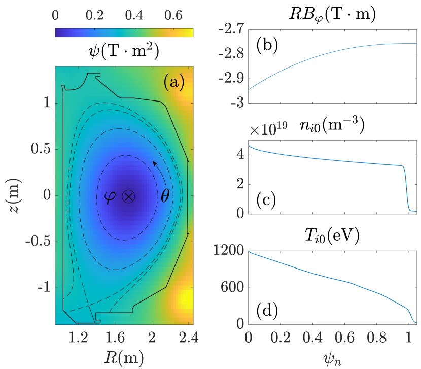
We use electrostatic XGCa simulations to study an axisymmetric H-mode plasma in DIII-D geometry, with the plasma equilibrium from shot 141451 [18, 28, 29] (figure 1). The code uses cylindrical coordinates to describe the realistic toroidal geometry containing an X point (figure 1(a)), where means definitions. The equilibrium magnetic field is given by , where is the poloidal magnetic flux and is a flux function. Since (figure 1(b)), the ion magnetic drift points in the negative- direction, which is the forward- configuration. We will also simulate the backward- configuration where the sign of is reversed (), while all other signs and plasma input profiles are kept the same. Since increases radially, the poloidal magnetic field is positive. If one reverses the sign of while keeping unchanged, then the plasma will behave the same except that the toroidal-rotation direction is reversed. The code utilizes unstructured triangular meshes, with most of the mesh nodes aligned with magnetic field lines [30]. For our simulations, the mesh has a radial grid size of and a poloidal grid size of . The normalized flux is defined as , where and are the value of at the magnetic axis and at the LCFS, respectively.
We simulate deuterium ions with mass and charge number , where is the proton mass. The input ion density and temperature are functions only of , and are shown in figures 1(c) and 1(d). The ion gyrocenter coordinates are position , magnetic moment , and parallel momentum . Their characteristics are governed by equations given in Ref. [11], which are mathematically equivalent to the following:
| (1) | |||
| (2) |
and . Here, the overhead dot denotes the time derivative, , , , is the gyrocenter Hamiltonian, is the parallel velocity, is the elementary charge, is the gyroaveraging operator, and is the electrostatic potential. Note that for the present electrostatic formulations.
Using the the “total-f” simulation method [31], the code calculates both the total gyrocenter ion orbits and distribution function . The gyrocenter distribution function is chosen to be Maxwellian at the beginning of the simulation:
| (3) |
but it quickly evolves to a neoclassical equilibrium distribution function with steep plasma gradient. The code uses two marker particle weights: time-invariant and time-varying. The time-invariant weights are used for initial marker particle loading in 5D phase space. At , the time-varying ion markers’ weights evolve such that advances in time according to
| (4) |
Here, is a nonlinear Fokker–Planck–Landau collision operator [32, 33] and represents sources (such as heating, torque input, and neutral ionization and charge exchange) and sinks (such as radiative heat loss). In our simulations, only the effects from are retained, while is assumed to be zero. The wall perfectly absorbs ions. This is done by flipping the sign of for the ion markers that hit the wall and changing their time-varying weights such that the outgoing [13].
Let us define the velocity-space integration as
| (5) |
The ion-density perturbation is then , and can be calculated from the gyrokinetic Poisson equation (with ):
| (6) |
where denotes gradient perpendicular to . For the electron-density perturbation , we adopt the adiabatic-electron model, which assumes
| (7) |
Here, and are the equilibrium electron density and temperature, respectively. We have from charge neutrality, and it is assumed that . Also, is the flux-surface average, where is the Jacobian, and the integration over is omitted due to the axisymmetry in XGCa. Note that for the SOL region, the flux-surface average is performed along open (rather than closed) field lines between two wall-contacting points.
When solving the gyrokinetic Poisson equation (6), the boundary condition is at the wall, at the private-flux region below the X point, and where . For the results presented in this article, we chose , but we also found that inside the LCFS is insensitive to the value of , as long as it is not too close to unity. Since we used the adiabatic-electron model (7), realistic electron dynamics and the sheath-boundary effects in the SOL are not included in our simulations. Kinetic electrons and sheath models should be included in the future in order to properly account for these effects [13].
The electron radial current vanishes with the adiabatic-electron model (7). Then, the total ion radial current must also vanish due to the quasineutrality constraint, . Therefore, to avoid confusion, we will refer to the ion radial gyrocenter flux rather than the total ion radial current in the rest of the paper. Note that although can be nonzero, physically it is always balanced by the classical polarization flux , which corresponds to the left-hand side of the gyrokinetic Poisson equation (6). This ensures that the total ion radial current is zero and the plasma is quasineutral.
Finally, we mention that our simulation setup is similar to a previous study of the plasma edge rotation using an earlier version of the code [34], except that Ref. [34] had kinetic electrons. As will be shown in section 4.3, results on the edge rotation from our simulations are qualitatively similar to those reported in Ref. [34], except that Ref. [34] observed a radial electron current in the quasisteady state, while the adiabatic-electron model used here will set the radial electron current identically to zero. Since the edge rotation is not central to our study, we will not make quantitative comparisons.
2.2 Ion-orbit-flux diagnostic implementation
The ion-orbit-flux formulation uses the coordinates to label ion gyrocenter orbits that cross the LCFS, where is the canonical toroidal angular momentum and is a chosen “orbit Hamiltonian” [26, 27]. The formulation is exact with any time-dependent , provided that is axisymmetric. For XGCa, one straightforward choice is , but we will also make alternate choices to illustrate the formalism (section 3.2). The corresponding orbit characteristics are given by
| (8) | |||
| (9) |
with . One can also define the “remainder” Hamiltonian and the corresponding quantities
| (10) | |||
| (11) |
with . (Note that is always zero within this paper.) Let us define an orbit derivative at fixed time, [27]; then, (4) becomes
| (12) |
Note that (12) is exactly equivalent to (4), and we do not require to be smaller than . The orbits , parameterized by , are obtained by integrating (8) and (9) over a timelike variable at fixed true time . It is straightforward to show that and are constant along the orbits [27], namely,
| (13) |
Therefore, the orbits can be labeled by , and they must form closed loops on the 2-dimensional plane [27], unless they intersect the wall. This means that any orbit that leaves the LCFS must have also entered it earlier.
Using a coordinate transformation, the radial ion gyrocenter orbit flux through the LCFS can be expressed as [26]
| (14) |
Here, is the surface element. The range of is determined by varying from to at fixed and , and labels the local minimum and maximum of . For a given orbit, and are evaluated at the incoming and the outgoing points where the orbit crosses the LCFS. The difference between and can be calculated by integrating the orbit derivative along the orbits, i.e.,
| (15) |
Then, we have our ion-orbit-flux formulation ready for numerical evaluations:
| (16) |
Here, the remainder flux is from , the collisional flux is from , the source flux is from , and is from . The term arises whenever the remainder Hamiltonian is nonzero. For example, this would include effects from turbulence, when is non-axisymmetric. But can also include other effects. For example, in section 3.2.2, varies poloidally but is still axisymmetric. Then, the corresponding describes effects from neoclassical processes rather than from turbulence. Meanwhile, note that is not a transport or source term per se; rather, a nonzero is the result of imbalance between transport and sources along the orbits that give rise to Eulerian time change in .
To study steady-state transport and sources onto the loss orbits, we also define a loss-region function , such that for the loss orbits, which intersect the wall, and for the confined orbits, which do not intersect the wall. Then, by inserting into the integrand of (16), we get the loss-orbit contribution to the flux; namely, the remainder flux can be decomposed into the loss-orbit contribution and the confined-orbit contribution:
| (17) |
and similarly for , , and . Note that when evaluating from (15) for confined orbits, the integration path can be either the confined-region part of the orbit inside the LCFS, or the SOL part outside the LCFS. (Mathematically they yield the same results.) However, for loss orbits, the integration path can only be the confined-region part, as the SOL part will intersect the wall. It may therefore appear that the formalism misses effects from transport and sources along the SOL part of the loss orbits, e.g., scattering of loss-orbit particles from the SOL back into the confined region. However, their contribution is still entirely retained via . Specifically, in the SOL, transport and sources from the confined orbits to the loss orbits will result in nonzero of the loss orbits, which then contributes to . Similarly, transport and sources from the loss orbits to the confined orbits will change of the confined orbits, which then contributes to .
Finally, we note that the above formulations apply to any closed flux surface, not just the LCFS. For example, in section 3 below, the formulations are applied to a core flux surface .
The orbit-flux formulation (16) has been numerically implemented in XGCa. A separate ion-orbit code has been developed [35], which describes the orbits labeled by . Then, is calculated in XGCa according to (15). Finally, the orbit flux is obtained from (14), where is replaced with for XGCa. The ion-orbit code also determines the loss-orbit region with the function , so the loss-orbit contribution to the flux can be determined as in (17). To avoid repetitive XGCa simulations, we also made an alternative implementation where XGCa outputs , , and , then a separate code calculates the orbit flux [36].
3 Collisional relaxation of core
In this section, we demonstrate the validity of our ion-orbit-flux diagnostic by studying the neoclassical at a core flux surface . Results in this section are from the forward- configuration with . Results for the backward- configuration are similar.
3.1 Plasma properties in quasisteady state
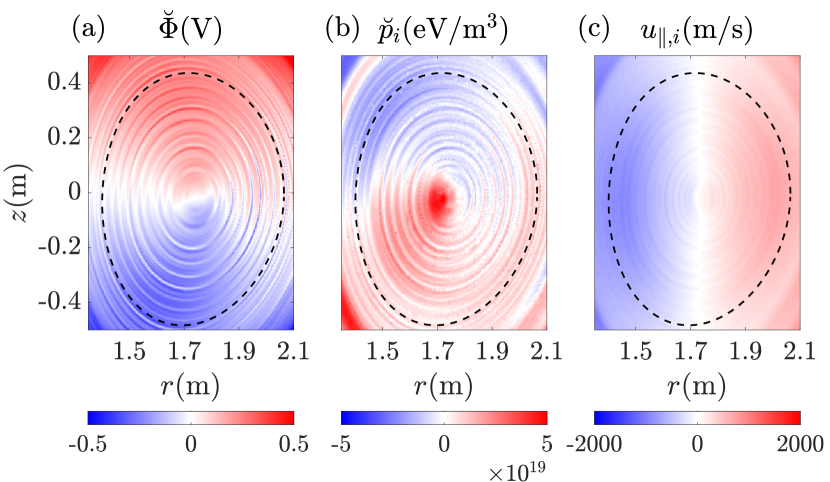
The initially Maxwellian distribution function does not correspond to a neoclassical equilibrium, so geodesic-acoustic-mode (GAM) oscillations are excited. However, the GAM oscillations are quickly damped by Coulomb collisions and ion Landau damping, after which the system reaches a quasisteady state. Figure 2 shows the nonzonal potential perturbation , the nonzonal ion-pressure perturbation where , and the ion fluid parallel velocity in the quasisteady state. (We use the breve notation here to denote nonzonal quantities, because the more standard tilde notation has already been used in section 2.2 for other purposes.) Since we focus on the core flux surface in this section, we only show these field quantities around this surface. It is seen that both and have up-down dipolar structures but they are out of phase, so the parallel electric field is against the ion parallel pressure gradient. Note that the nonzonal ion-gyrocenter density perturbation is in phase with because of the adiabatic-electron model (7), assuming in the core. Therefore, and are also out of phase, due to a nonzonal ion-temperature perturbation out of phase with . Meanwhile, has a left-right dipolar structure, so the plasma flows from the bottom () to the top (). Such a would cause a density buildup at the top, but the perpendicular flow makes the total plasma flow divergence-free.
Since is not a flux function, we look at the following quantity
| (18) |
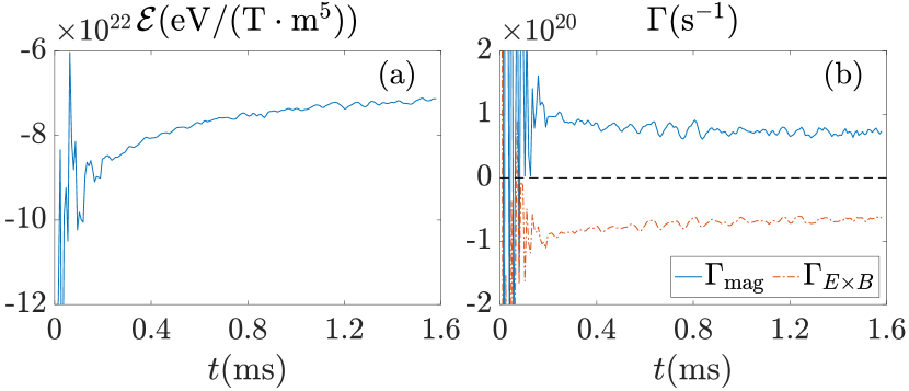
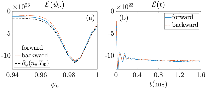
which can be considered as the radial electric force on ions from the zonal . In the following, we use zonal and interchangeably. Figure 3(a) shows the time evolution of at the surface. After the initial GAM oscillations, goes through a slower collisional damping process until it relaxes to its neoclassical value. The gyrokinetic Poisson equation (6) relates the zonal with the volume-integrated . Therefore, from the continuity relation, the ion radial gyrocenter flux must also vanish as approaches a constant value in the present adiabatic electron model applied to the core plasma.
Let us separate the radial gyrocenter flux into the magnetic-drift part and the -drift part:
| (19) |
where and . Figure 3(b) shows that and in the quasisteady state, such that the total flux is zero. These results are consistent with the dipolar structures of and shown in figure 2. Namely, since for and the magnetic drift points in the negative- direction, the net magnetic flux is radially outward, . Meanwhile, the drift points in the negative- direction, and is stronger at the outboard side () than the inboard side (); hence, the net flux is radially inward, .
3.2 Ion-orbit-flux diagnostic results
Below, we show the orbit-flux diagnostic results using two different orbit Hamiltonians: (section 3.2.1) and (section 3.2.2). With , we will show that the results of and are consistent with the collisional relaxation of . With , the orbit flux also contains a nonzero due to the nonzero . The physical meaning of will be briefly discussed in this section. The source flux will not be considered, since is set to zero.
3.2.1 Results with .
Since equals the true Hamiltonian , the orbit characteristics (governed by (8)) are the same as the true characteristics (governed by (1)). Then, comparing (16) and (19), the orbit flux is
| (20) |
where we put a superscript “1” on (meaning or ) to indicate that they are evaluated along . Since and decreases during the collisional relaxation (figure 3(a)), the net radial flux is negative, so we expect to be negative. This expectation is confirmed by the results shown in figure 4(a). The collisional flux is negative, corresponding to a radially inward current induced by viscosity. The term is positive, but the net radial flux is negative and damps to zero, consistent with the collisional relaxation of .
3.2.2 Results with .
To further explore the formulation, we can alternatively choose , which only includes the zonal part of . Since , the orbit characteristics (governed by (8)) are different from the true characteristics (governed by (1)). Specifically, the magnetic drifts in and are the same, but the drift in is always tangent to flux surfaces (assuming in the core). Therefore, the -drift contribution to the orbit flux vanishes, leaving only the magnetic-drift contribution:
| (21) |
Here, comes from the remainder Hamiltonian . For emphasis, the nonzonal potential varies along the poloidal direction, but is still axisymmetric. We put a superscript “2” on to indicate that they are evaluated along , which is different from since .
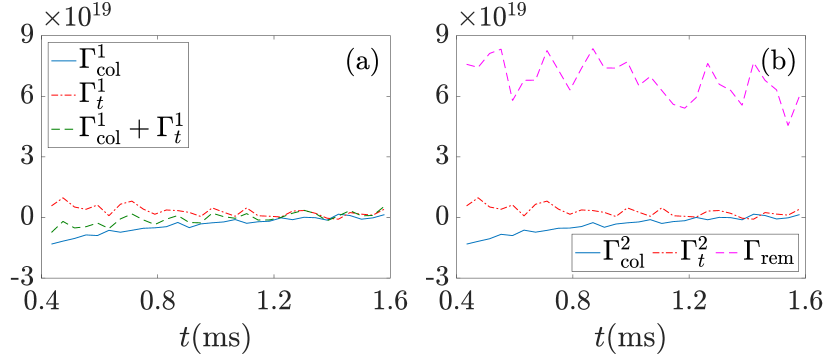
Figure 4(b) shows the orbit-flux diagnostic results with . Because in the core (figures 1(d) and 2(a)), the difference between and is tiny, and and are almost identical. Consequently, there is no visible difference between in figure 4(b) and in figure 4(a). With , and by comparing (20) and (21), we expect . This expectation is also confirmed by the results shown in figure 4(b), namely, is approximately the same as in figure 3(b).
In this case, most of comes from the acceleration term , while the contribution of the advection term is small and fluctuates around zero. This finding is consistent with the ordering estimate that and , so the ratio between the two terms is , which is very small in the core. Here, is an equilibrium length scale, is ions’ thermal speed, and is the poloidal gyroradius. For emphasis, this ordering is specific to our axisymmetric system in the core, and would not hold if contained turbulent fluctuations.
The fact that is nontrivial. Both fluxes stem from the nonzero , but is evaluated at the surface, while is evaluated along the orbits that cross the surface. Further, since in steady state, we have . Recalling (15) and (12), this reveals that the steady-state positive is supported by the acceleration from the parallel electric field . Specifically, since the magnetic drift points in the negative- direction, orbits’ incoming points are at the top of the flux surface and the outgoing points are at the bottom. Co-current ions () move counterclockwise to the inboard side where , so the corresponding parallel acceleration term is positive, assuming at . Similarly, counter-current ions () move to the outboard side where , so is also positive for them. Therefore, at the bottom (figure 2(b)) and the net magnetic-drift flux is positive, .
4 Effects of ion orbit loss on edge
In this section, the orbit-flux diagnostic is used to study the effects of ion orbit loss on the edge . Results from the forward- and backward- configurations are compared. It is found that the radial electric force on ions from approximately balances the ion radial pressure gradient for both configurations, indicating that the radial force on ions plays only a minor role. For the orbit-flux diagnostic results, both and are nonzero but they cancel each other. The loss-orbit contribution to the flux is estimated to be , which is found to be able to drive away by a few percent from its standard neoclassical solution. The nonzero is related to a toroidal-rotation acceleration in the edge that persists even when is quasisteady.
4.1 Ion-orbit-flux diagnostic results
Figure 5 shows at the edge. A large well is developed inside the LCFS, similar to experimental observations. The resulting radial electric force on ions approximately balances the radial ion pressure gradient caused by the density and temperature pedestal shown in figure 1(c). For the forward- case, the value of at the trough slowly grows more negative in quasisteady state (figure 5(b)). For the backward- case, also shifts in the negative direction, but even more slowly. The increase of for the forward- case indicates a small radially outward gyrocenter ion flux, which is estimated to be ; for the backward- case, is even smaller.
For the orbit-flux diagnostic, we choose so the orbit fluxes consist of and . The loss-orbit contribution to the fluxes is also calculated using the loss-region function , which is numerically determined by the ion-orbit code [35]. The loss orbits make up about 30% of all the orbits considered, that is . This percentage is not significantly different between the forward- and backward- configurations, since the two cases have the same magnetic-field topology and similar levels of . We have also verified that the shape of the loss region from our numerical (not shown) is consistent with some earlier analytic studies [15, 37, 38].
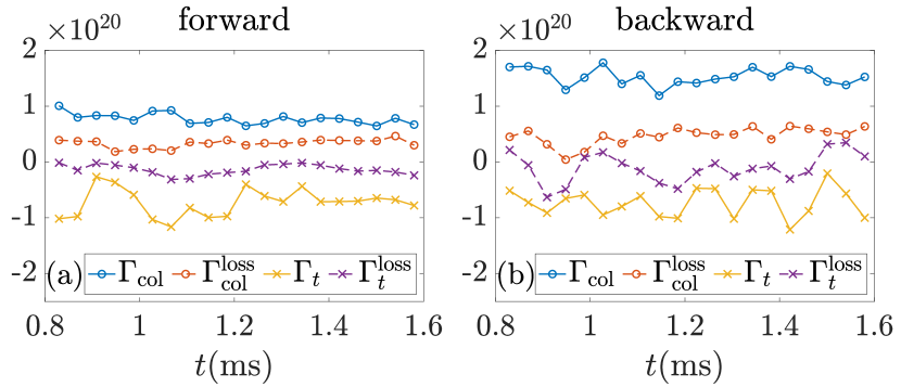
Figure 6 shows the orbit-flux diagnostic results at the LCFS (). Unlike the core (figure 4), here at the edge and do not vanish in quasisteady state, and their magnitudes are both large, . But and , so the total orbit flux is much smaller. Similarly, for the loss-orbit contribution, and . Due to the cancellation between and , the net loss-orbit flux appears to be small, making its accurate evaluation difficult in the presence of numerical fluctuations. For this reason, we only provide an estimate of the loss-orbit flux, which is . The magnitudes of are similar between the forward- and the backward- configurations. The small value of could be a result of the large providing good magnetoelectric confinement of ions [39].
Note that is on the same level as the estimated net ion gyrocenter flux for the forward- configuration. Therefore, may not be entirely balanced by the confined-orbit flux in quasisteady state for this case. For the backward- configuration, however, the estimated is much smaller than ; hence, the assumption that balances works better for this case.
4.2 Effects of on
Let us integrate the gyrokinetic Poisson equation (6) over the volume inside the LCFS. From Gauss’s law, we have
| (22) |
where and is the volume element. Since the right-hand side of (22) is approximately the perturbation of number of gyrocenter ions inside the LCFS, we take the time derivative of (22) and use the continuity equation. This gives a relation between the ion radial gyrocenter flux and the radial electric field:
| (23) |
(The electron radial flux is zero due to the adiabatic-electron assumption.) The right hand side represents the ion radial polarization flux. We can further separate into the confined-orbit contribution and the loss-orbit contribution, . Without orbit loss, , and would approach its standard neoclassical solution , which is determined by [19, 20, 21, 22]
| (24) |
Suppose a nonzero leads to in steady state. We then have
| (25) |
For simplicity, let us assume that damps towards with a neoclassical collisional poloidal-rotation damping rate . Then, from (23) and (25), is estimated from the following relation:
| (26) |
The factor in the integrand on the left hand side follows from the dielectric response of a homogeneous magnetized plasma, while is due to collisional poloidal-rotation damping by magnetic inhomogeneity in a tokamak plasma [21].
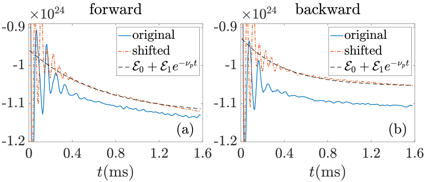
To estimate without the effects from ion orbit loss, we ran XGCa simulations again, but with the equilibrium profile of and radially shifted inwards by . Figure 7 shows a comparison of between the simulations with the original profile and the shifted profile. The magnitude of is smaller by a few percent for the shifted equilibrium profile. However, the collisional damping rate of is similar between the two profiles, suggesting that the collisional damping mechanism is similar whether there is gyrocenter orbit loss or not. By fitting the numerical results to an analytic form , we estimate for the forward- case, and for the backward- case (figure 7). Both estimates of are the same order of magnitude as the local ion-ion collision rate , which is calculated using and at the edge [40]. Assuming , together with and , we estimate the relative change of as
| (27) |
This is consistent with figure 7, in which for the shifted profiles is within a few percent of for the original profiles, although the shifted-profile calculations involve almost no loss orbits. For these simulations, we thus conclude that is too small to drive significantly away from . A modest difference in is observed between the forward- and backward- configurations. However, a similar difference also exists in the shifted-profile simulations (figure 7), suggesting that it may in fact follow from the difference in the toroidal rotation profile.
4.3 Toroidal-rotation acceleration at the edge
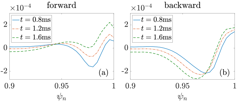
The fact that is nonzero indicates that the gyrocenter distribution function is changing over time. Since the density moment of is not changing much, consistent with the quasisteady profile, we will look for a change in the first moment of , namely, the parallel flow velocity. Figure 8 shows the flux-surface averaged parallel-flow contribution to the toroidal angular momentum density in the edge. Because , the equilibrium plasma current is oppositely directed to ; hence, a positive (negative) toroidal angular momentum corresponds to a counter- (co-) current rotation. As shown in the figure, at an earlier time the toroidal rotation has a co-current peak inside the LCFS, consistent with previous results [11, 18, 34]. As time progresses, however, there is a counter-current acceleration just inside the LCFS for both configurations. (As one moves further inside radially, the acceleration shifts to the co-current direction.) Both the toroidal-rotation velocity and acceleration are much stronger at the outboard than at the inboard.
The counter-current toroidal acceleration just inside the LCFS is consistent with the negative . Counter-current acceleration at fixed density implies an increase of counter-current ions and a decrease of co-current ions. At the outboard midplane, where the acceleration is concentrated, most co-current ions are on orbits that remain inside the LCFS, which do not contribute to the orbit flux. Many counter-current ions are on orbits that do cross the LCFS, thus the counter-current acceleration results in a net positive in the counter-current velocity space in (16), which corresponds to a negative .
For electrostatic simulations with the adiabatic-electron model (7), the toroidal angular momentum is conserved [41, 42]. Although the toroidal angular momentum consists of both a parallel-momentum portion (shown in figure 8) and an portion, the latter is almost constant in time here, because is quasisteady. The observed toroidal-rotation acceleration therefore indicates a change of the toroidal-angular-momentum density, hence a nonzero radial toroidal-angular-momentum flux. We also observed qualitatively similar counter-current toroidal-rotation acceleration in simulations with shifted equilibrium profiles, suggesting that this acceleration is not solely driven by effects specific to the edge. These observations will be the subject of future studies.
5 Conclusions and discussion
The ion-orbit-flux formulation [26, 27] has been implemented as a numerical diagnostic in XGCa [25, 35, 36]. The diagnostic measures the separate contributions to the ion orbit loss from different transport mechanisms and sources. The validity of the diagnostic is demonstrated by studying the collisional relaxation of in the core. Then, the diagnostic is used to study effects of ion orbit loss on at the edge of a DIII-D H-mode plasma. Under the given neoclassical pedestal plasma density and temperature profiles and without considering neutral particles, the radial electric force on ions from approximately balances the ion radial pressure gradient in the edge pedestal. The existence of a small ion gyrocenter orbit loss flux does not drive significantly away from its standard neoclassical solution, because of the collisional poloidal-rotation damping and the large radial dielectric response of tokamak plasma. In other words, once the edge pedestal is established by some mechanism, its is not very sensitive to the existence of a small radial current perturbation.
The role of collisional ion orbit loss in a full-current ITER edge plasma is important and is left for a subsequent study. A recent report has shown that due to weak neoclassical effect in the full-current ITER, the plasma pressure gradient near the magnetic separatrix will not be balanced by , but will be balanced by strong toroidal rotation driven by turbulent orbit loss [43]. It is of interest to see if similar results also hold for an axisymmetric neoclassical ITER plasma.
Data Availability
Digital data can be found in DataSpace of Princeton University [44].
References
References
- [1] Chang C S, Kue S and Weitzner H 2002 Physics of Plasmas 9 3884–3892
- [2] Shaing K 2002 Physics of Plasmas 9 1–3
- [3] Ku S, Baek H and Chang C S 2004 Physics of plasmas 11 5626–5633
- [4] Stacey W M 2011 Physics of Plasmas 18 102504
- [5] Itoh S I and Itoh K 1988 Physical Review Letters 60 2276
- [6] Shaing K C and Crume Jr E 1989 Physical Review Letters 63 2369
- [7] Connor J and Wilson H 2000 Plasma Physics and Controlled Fusion 42 R1
- [8] Stoltzfus-Dueck T 2012 Physical Review Letters 108 065002
- [9] Battaglia D, Burrell K, Chang C, Ku S, Degrassie J and Grierson B 2014 Physics of Plasmas 21 072508
- [10] Boedo J, DeGrassie J, Grierson B, Stoltzfus-Dueck T, Battaglia D, Rudakov D, Belli E, Groebner R, Hollmann E, Lasnier C et al. 2016 Physics of Plasmas 23 092506
- [11] Chang C S, Ku S and Weitzner H 2004 Physics of Plasmas 11 2649–2667
- [12] Chang C, Ku S, Tynan G, Hager R, Churchill R, Cziegler I, Greenwald M, Hubbard A and Hughes J 2017 Physical Review Letters 118 175001
- [13] Ku S, Chang C, Hager R, Churchill R, Tynan G, Cziegler I, Greenwald M, Hughes J, Parker S E, Adams M et al. 2018 Physics of Plasmas 25 056107
- [14] Brzozowski III R W, Jenko F, Bilato R, Cavedon M and Team A U 2019 Physics of Plasmas 26 042511
- [15] DeGrassie J, Groebner R, Burrell K and Solomon W 2009 Nuclear Fusion 49 085020
- [16] deGrassie J S, Boedo J A and Grierson B A 2015 Physics of Plasmas 22 080701
- [17] Pan C, Wang S and Ou J 2014 Nuclear Fusion 54 103003
- [18] Seo J, Chang C, Ku S, Kwon J, Choe W and Müller S H 2014 Physics of Plasmas 21 092501
- [19] Hinton F and Rosenbluth M N 1973 The Physics of Fluids 16 836–854
- [20] Hazeltine R 1974 The Physics of Fluids 17 961–968
- [21] Hirshman S P 1978 Nuclear Fusion 18 917
- [22] Hirshman S and Sigmar D 1981 Nuclear Fusion 21 1079
- [23] Shaing K C 1992 Physics of Fluids B: Plasma Physics 4 171–175
- [24] Shaing K C 1992 Physics of Fluids B: Plasma Physics 4 3310–3315
- [25] See https://www.osti.gov/doecode/biblio/12570 for more details about the code XGC.
- [26] Stoltzfus-Dueck T 2020 Nuclear Fusion 60 016031
- [27] Stoltzfus-Dueck T and Zhu H 2021 Plasma Physics and Controlled Fusion 63 115001
- [28] Müller S, Boedo J, Burrell K, DeGrassie J, Moyer R, Rudakov D and Solomon W 2011 Physical Review Letters 106 115001
- [29] Müller S, Boedo J, Burrell K, Degrassie J, Moyer R, Rudakov D, Solomon W and Tynan G 2011 Physics of Plasmas 18 072504
- [30] Zhang F, Hager R, Ku S H, Chang C S, Jardin S C, Ferraro N M, Seol E S, Yoon E and Shephard M S 2016 Engineering with Computers 32 285–293
- [31] Ku S, Hager R, Chang C S, Kwon J and Parker S E 2016 Journal of Computational Physics 315 467–475
- [32] Yoon E and Chang C 2014 Physics of Plasmas 21 032503
- [33] Hager R, Yoon E, Ku S, D’Azevedo E F, Worley P H and Chang C S 2016 Journal of Computational Physics 315 644–660
- [34] Chang C S and Ku S 2008 Physics of Plasmas 15 062510
- [35] Contact the authors for more details about the ion-orbit code.
- [36] Contact the authors for more details about the orbit-flux code.
- [37] Chankin A and McCracken G 1993 Nuclear Fusion 33 1459
- [38] Miyamoto K 1996 Nuclear Fusion 36 927
- [39] Stix T H 1971 The Physics of Fluids 14 692
- [40] Huba J D 2004 Revised NRL plasma formulary (Naval Research Laboratory)
- [41] Scott B and Smirnov J 2010 Physics of Plasmas 17 112302
- [42] Stoltzfus-Dueck T and Scott B 2017 Nuclear Fusion 57 086036
- [43] Chang C S, Ku S, Hager R, Churchill R M, Hughes J, Köchl F, Loarte A, Parail V and Pitts R 2021 Phys. Plasmas 28 022501 https://doi.org/10.1063/5.0027637
- [44] See https://dataspace.princeton.edu/handle/88435/dsp01pz50gz45g for the digital data.