Toward Efficient and Robust Multiple Camera Visual-inertial Odometry
Abstract
Efficiency and robustness are the essential criteria for the visual-inertial odometry (VIO) system. To process massive visual data, the high cost on CPU resources and computation latency limits VIO’s possibility in integration with other applications. Recently, the powerful embedded GPUs have great potentials to improve the front-end image processing capability. Meanwhile, multi-camera systems can increase the visual constraints for back-end optimization. Inspired by these insights, we incorporate the GPU-enhanced algorithms in the field of VIO and thus propose a new front-end with NVIDIA Vision Programming Interface (VPI). This new front-end then enables multi-camera VIO feature association and provides more stable back-end pose optimization. Experiments with our new front-end on monocular datasets show the CPU resource occupation rate and computational latency are reduced by 40.4% and 50.6% without losing accuracy compared with the original VIO. The multi-camera system shows a higher VIO initialization success rate and better robustness overall state estimation.
I INTRODUCTION
Visual-inertial state estimation serves as the most fundamental role for a wide range of applications, such as robotic navigation, autonomous driving, and augmented reality (AR) [1]. Current monocular and stereo Visual-inertial Odometry systems have achieved great success for state estimation [1, 2, 3]. Generally, a VIO algorithm composes of a front-end to process image data and a back-end that carries out the optimization. However, because of the substantial visual data stream, the front-end usually takes extensive CPU resources, yielding the computation latency and incompatibility with other tasks on a computation-limited chip. Additionally, monocular and stereo VIO sensors have limited field-of-view (FoV), making the state output unstable when the observed scene is homogeneous. These two main challenges make the state-of-the-arts far away from real applications.
The VIO front-end is usually used to extract landmark features and track features among video frames. To ensure the stability of feature tracking, the input videos are often at a high frequency above 20 Hz. Consequently, it takes a large proportion of CPU resources to guarantee real-time performance. Jeon [4] tests the CPU usage of different VIO algorithms on various NVIDIA hardware (Jetson TX2, Xavier NX, and AGX Xavier boards). His work shows that most of the VIO algorithms have extensive CPU usages around 150%250%. Besides, computation latency resulted from the high video frame rate and limited CPU capability is a significant problem for real-time VIO systems. The accumulating delay will get worse when the system operates for a long time. To overcome the computation latency, the SOTA methods [1, 2, 3] limit the number of tracked features. However, the CPU occupation remains high. In this work, we build a new front-end to release the CPU usage and the computation latency while the estimation accuracy maintains or even gets improved.
Robustness is another vital metric for VIO systems. Although the current SOTA monocular and stereo VIO systems have achieved stable performance on most public datasets, the limited scenarios and motion patterns in existing public datasets [5] making such stability unreliable. In typical cases, such as when the cameras face close to objects, the limited FoV of monocular and stereo cameras results in significant occlusion, making the feature tracking performance unstable.
To account for this problem, numerous works [6, 7, 8] have been proposed to use multiple cameras to increase the FoV. Thus the most stable tracking features can be selected among these cameras. However, the computational burden will increase significantly as the number of cameras increases. This kind of computation occupation prevents other applications, such as object detection and motion planning, from running on the same computer. Therefore, there is a great need to enable a multi-camera VIO system to handle massive visual data at a low CPU usage.
To address the above two problems when improving the efficiency and robustness of VIO systems, we mainly focus on incorporating the graphics processing units (GPUs) enhanced modules into the VIO algorithms. Recently, the powerful embedded GPUs have been utilized as the front-end of VIO to improve the information processing capability [9]. In this paper, we first incorporate the Vision Programming Interface (VPI) toolbox [10] to propose a new GPU accelerated VIO front-end, which significantly reduces the CPU usage and maintains the state estimation efficiency and accuracy. Then we further extend the monocular VIO to a multi-camera VIO system, where cameras have non-overlapping FoV. All the front-end tasks are conducted on GPU with VPI, and all the features are integrated into one back-end with IMU measurements. The configuration of multi-camera VIO finally improves the initialization success rate and robustness on extensive evaluation with our collected datasets. The major contributions are listed as follows:
-
•
We propose a GPU enhanced front-end implemented by VPI for low cost on computational latency and CPU usage while maintaining state estimation accuracy and robustness.
-
•
With the efficient front-end, we extend the monocular pipeline to a multi-camera VIO system. All the features observed in multiple cameras are fed into the back-end for optimization, which provides a higher system initialization success rate and more robust state estimation.
The rest of this paper is organized as follows. Section II provides the related literature. Section III describes the VPI accelerated front-end and the multi-camera VIO system. Section IV provides the experimental results and discussions. Finally, this paper is concluded in Section V.
II RELATED WORK
II-A GPU Accelerated VIO Algorithms
Numerous VIO algorithms have been proposed in recent years, such as VINS-Mono [1], MSCKF [11], ROVIO [2] and ORB-SLAM3 [12]. Most of them consist of a front-end for feature association and a back-end for pose/map optimization. Although these VIO methods have achieved good results for online state estimation, The CPU usages are all high because massive visual images need to be processed. According to the experiments conducted on Xavier [4], the CPU usage of VINS-Mono is about 150-170 on multi-core processing, MSCKF is above 170%. ROVIO has the least CPU usages (around 60%), but the back-end EKF is less efficient compared to the bundle adjustment method [13]. The computational latency on the back-end will be larger in ROVIO. ORB-SLAM has the largest CPU usage ranging about 150-240. These large CPU occupations make the VIO systems cannot run on the same computer when robots have other tasks, such as object detection and motion planning. Additionally, the limitation to the CPU usage will increase the computational latency. Therefore, the trade-off between CPU usage and efficiency for VIO systems has always been a difficult problem.
With the hardware revolution in the last decade, GPUs are installed in embedded platforms, such as NVIDIA Xiaver, which enables more parallel computing capacity. Recently, several works have utilized GPUs to improve the VIO front-end video processing capability and reduce latency. The commonly used feature detectors, such as Shi-Tomasi [14], Harris [15], and FAST [16] are implemented in CUDA Visual Library (VILIB) [9] for fast feature extraction. VILIB applies efficient low-level, GPU hardware-specific programming for feature detection and feature tracking. Recently, NVIDIA proposed the Vision Programming Interface (VPI) [10]. VPI enables lots of basic computer vision algorithms (such as Harris detector and LK optical flow) on either CPU, GPU, VPA ( Programmable Vision Accelerator), and VIC (Video Image Compositor). It supports an easy switch between different processing chips. These GPU implementations have great potentials to shift the computational-expensive VIO front-end to GPU, reducing the CPU usage and computation latency.
II-B Multiple Camera Visual Odometry
Although the SOTA monocular and stereo VIO systems have impressive performance, they are still not robust enough for autonomous state estimation on real robots over a long period with complex motions and complicated environments. Multiple cameras can significantly add visual constraints with wider FoV and thus provide redundancy for back-end optimization. Taragay et al. proposed the loosely-coupled VIO system on two pairs of backward and forward stereo cameras with an IMU [6]. Tim et al. introduced a real-time 6D stereo visual odometry with two non-overlapping FoV cameras [7]. Liu et al. presented a pose tracker and a local mapper supporting an arbitrary number of stereo cameras [17]. These methods demonstrate the robustness of multi-camera visual odometry over a long traveling distance and complex environments. However, all the multi-camera processing is based on the multi-core CPU parallel computing, adding great computation burden to CPU and inevitably bringing computation latency to the state estimation. With the GPU accelerated front-end mentioned before, our goal is to set the front-ends of multiple cameras conducted on GPU without consuming any CPU resources so that the back-end optimization can have enough cores to ensure non-latency estimation.
III Methodology
III-A Overview
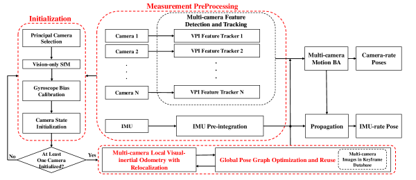
The structure of the proposed multi-camera visual-inertial state estimator is shown in Fig. 2. We first extract and track visual features from non-overlapping cameras individually with VPI tools. IMU measurements between two consecutive frames are preintegrated as in VINS-Mono [1]. The initialization procedure selects one principal camera to initialize and ends with initialization on all the subordinate cameras. It is regarded as a success if at least one camera is initialized successfully. All the cameras’ features will be included in the visual-inertial bundle adjustment. In terms of relocalization and pose graph, all the initialized cameras’ frames will be stored in the keyframe database for loop detection.
The notations and frame definitions that we use throughout the paper are defined as follows. , , and represent the i-th camera frame, body (IMU) frame and world frame, respectively. Rotation matrices and Hamilton quaternions both represent rotation. represents the multiplication operation between two quaternions. In our system, we assume that the IMU and cameras are already calibrated. Thus the extrinsic parameters are treated as known quantities.
III-B VPI-enhanced Front-end
The front-end of a VIO detects and tracks features, and passes the visual information to the back-end for optimization. VPI provides Harris corner detector to detect features and pyramidal LK optical flow to track features. The overall architecture of the front-end is demonstrated in Fig. 3.
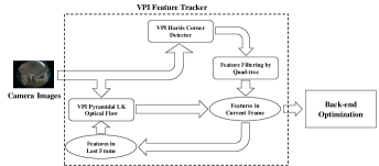
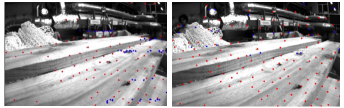
Image stream will be directly transferred to GPU, and we use the Harris corner detector in the VPI toolbox to detect features. To maintain the feature number and feature continuity between frames, features are ranked by the response scores. However, if the Harris features are picked directly according to their scores, their distribution will be concentrated in richly textured areas. This reduces the robustness in initializing the VIO and state estimation. Inspired by ORB-SLAM [3], we propose to use the quad-tree algorithm to filter the feature points. The point with the highest response score will be selected regardless of how many points in a local patch. It ensures a more uniform distribution of feature points, as shown in Fig. 4. The incoming image will also be transferred to pyramidal LK optical flow to track the feature points in the last frame. The newly detected feature points and the tracked points constitute the feature points in the current image. They will be passed to the back-end for further processing. Data storage and information transportation are purely based on VPI defined data structures, which allow minimum cost on transporting data between CPU and GPU.
III-C Estimator Initialization
Since the cameras have non-overlapping FoV, the system needs an accurate scale initialization at the beginning, similar to the monocular tightly coupled VIO [1]. We get the necessary initial values by loosely aligning IMU preintegration with the vision-only structure. The estimator initialization for the multi-camera system consists of principal camera selection, vision-only SfM on principal camera, gyroscope calibration, and camera state initialization.
III-C1 Principal Camera Selection
The initialization starts with a principal camera selection. In the sliding window, we check the feature correspondences in each camera between the latest frame and all previous frames. After we find stable feature tracking (more than 30 tracked features) between the latest frame and one typical frame in the sliding window, the camera with the most visual features is selected as the candidate of the principal camera. If the parallax is sufficient (more than 20 pixels), it is regarded as the principal camera. Otherwise, we continue the selection within other cameras. Once the principal camera is identified, the other cameras are characterized as subordinate cameras, and their initialization depends on the initialization of the principal camera.
III-C2 Vision-only SfM on Principal Camera
Once we identify a principal camera and the corresponding two frames, we perform a vision-only SfM [1] on the principal camera. We set the first principal camera frame as the reference world frame for SfM. Here we denote as the principal camera and as subordinate cameras. Given the extrinsic parameters between the camera and the IMU, we can recover the frame rotations of subordinate cameras with respect to as
| (1) |
Note that the scale of principal camera is unknown at this stage, so we cannot directly obtain the translation of subordinate cameras using extrinsic parameters. will be solved in the next.
III-C3 Gyroscope Bias Calibration
Considering two consecutive frames and in the window, we get the rotation , and . In addition, we have different values for each , denoted as , where indicates that the body rotation is obtained from the i-th camera using extrinsic parameter . We linearize the IMU preintegration term with respect to gyroscope bias and minimize the following cost function:
| (2) |
where , index all frames in the window and all the cameras, respectively. is the IMU preintegration constraint defined in [1]. In such a way, we get an initial calibration of the gyroscope bias . Then we follow the same way as in [1] to repropagate all IMU preintegration terms using the new gyroscope bias.
III-C4 Camera States Initialization
After the gyroscope bias is initialized, we move on to initialize velocity in the body frame, gravity vector and metric scale by aligning the up-to-scale visual structure with IMU measurements and refining the gravity [1].
After the visual alignment on the principal camera, we move on to initialize the subordinate cameras. We first proceed to recover the translation of subordinate cameras using the extrinsic between cameras and IMU
| (3) |
Now we triangulate all the feature points observed in the subordinate cameras.
Once the principal camera initializes successfully, the initialization is regarded as a success. All the values are rotated to the world frame and fed into the tightly coupled multi-camera VIO.
III-D Tightly Coupled Multi-camera VIO
After estimator initialization, a sliding window based tightly coupled multi-camera VIO proceeds. We incorporate the inverse distances of features in multiple cameras into the optimization. The state vector is defined as
| (4) | ||||
where is the IMU state at the time when the k-th image is captured. It contains position, velocity, and orientation of the IMU in the world frame, acceleration bias and gyroscope bias in the IMU body frame. is the total number of keyframes, is the total number of initialized cameras, and is the total number of features of the i-th camera in the sliding window. is the inverse distance of the j-th feature in the i-th camera from its first observation.
A visual-inertial bundle adjustment is performed to estimate the states. The formulation is
| (5) | |||
is the cauchy robust function used to suppress outliers. is the set of all IMU measurements. is the set of all initialized cameras. is the set of features that have been observed at least twice in the current sliding window in the i-th camera. is the prior information from marginalization. is the residual for IMU. is the residual for visual measurements. The detailed definitions are presented in [1]. is defined as
| (6) |
where , are the number of features in the i-th camera and the maximum number of features observed in one typical camera, respectively.
III-E Relocalization
The relocalization generally follows the scheme in [1]. The only difference is that the frames from different cameras are all stored in the previous map for loop detection and feature retrieval. A loop match detected in any camera will trigger the relocalization.
IV Experimental results
In this section, we present the results of the VPI-enhanced VINS-Mono and the final multi-camera VIO.
IV-A VINS-Mono with VPI
To demonstrate the effectiveness of the proposed new front-end in terms of CPU usage and computation latency, we test different VIO methods on EuRoC dataset [18]. The used CPU for testing is AMD Ryzen 5800H with Radeon Graphics 3.20GHz. For each video sequence, we conduct five trials for both the original VINS-Mono and our VPI enhanced VINS-Mono with Harris corner (VINS-VPI-Harris). In addition, we deploy another GPU enhanced front-end from VILIB [9] into VINS-Mono for comparison. In VILIB, we test two feature detectors, Harris and FAST [19]. Therefore, we add another two versions for comparison, VINS-VILIB-FAST and VINS-VILIB-Harris. We use the modules provided in rpg_trajectory_repository [20] to quantitatively evaluate and compare the results. The main comparison metrics consist of 1) the CPU usage and 2) the time of different VIO front-ends, and 3) the average absolute trajectory errors (RMSE) on translation and rotation of 5 times’ trials. Table I shows the CPU usage and time cost of different VIO front-ends on the EuRoC dataset.
for different VIO methods on EuRoC dataset
| Method | CPU usage (%) | Time (ms) |
| VINS-Mono | 52 | 15.4 |
| VINS-VPI-Harris | 31 | 7.8 |
| VINS-VILIB-FAST | 49 | 8.5 |
| VINS-VILIB-Harris | 51 | 8.7 |
Table I shows VINS-Mono-VPI has the most significant reduction on CPU usage and time cost, achieving a reduction of 40.4% and 50.6% compared with the original VINS-Mono, respectively. Modules from VILIB (including VINS-VILIB-FAST and VINS-VILIB-Harris) reduce the front-end time cost, but they still have very high CPU usages. These results are from all the 11 video sequences in EuRoC dataset.
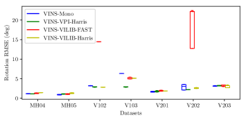
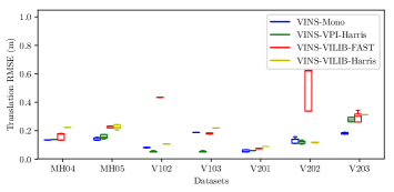
Fig. 5 and Fig. 6 show the trajectory evaluation results on 7 relatively difficult sequences of EuRoC dataset. Compared with the original VINS-Mono, VINS-VPI-Harris has the most competitive performance in terms of translation and rotation errors. In some sequences, like V1_02, V1_03, and V2_02, VINS-VPI-Harris obtains better accuracy. On the other hand, VINS-Mono with VILIB loses accuracy to some extent, especially for the FAST feature when testing on V1_02 and V2_02 sequences. These results demonstrate that the VPI-enhanced VINS-Mono can not only reduce the CPU usage and time cost, but also maintain stable state estimation.
IV-B Multi-camera VIO
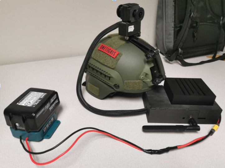
To test the performance of the proposed multi-camera VIO method with the VPI-enhanced front-end and the tightly-coupled back-end, we collect our own data using a pedestrian carried system (as shown Fig. 7) with two non-overlapping fisheye cameras. The two Leopard IMX264 cameras capture fisheye images ( pixels images at 24.5Hz) with a synchronized Epson g365 IMU (200Hz). We provide five datasets: Outdoors, Indoors, Corridor, NSH wall, and Smith Hall, to evaluate the performance and compare it with monocular VIO results. The outdoor and indoor datasets are mainly used to test the VIO system initialization performance. Since it is hard to obtain the ground truth trajectories for both indoor and outdoor datasets, the other three datasets are provided with accurate 3D point cloud maps [21] for VIO result evaluation.
for different VIO methods with a fisheye camera
| Method | CPU usage (%) (single core) | Time (ms) (front-end) |
| VINS-Mono | 91 | 20.6 |
| VINS-VPI-Harris | 43 | 11.7 |
| VINS-VILIB-FAST | 82 | 28.7 |
| VINS-VILIB-Harris | 91 | 16.2 |
of multi-camera VIO and VINS-Mono
| VIO | VINS-Mono | multi-camera VIO |
| Time (back-end) | 40 ms | 40 ms |
| CPU usage (front-end) | 91 % | 43%(each cam) |
| CPU usage (back-end) | 101% | 105% |
| multi-camera VIO | VINS-VPI-Harris cam-1 | VINS-VPI-Harris cam-2 | VINS-Mono cam-1 | VINS-Mono cam-2 | ||||||
| RMSE | num | RMSE | num | RMSE | num | RMSE | num | RMSE | num | |
| Corridor | 0.105893 | 14743 | 0.111162 | 3017 | 0.114349 | 5909 | 0.114252 | 5410 | 0.104852 | 10860 |
| Smith Hall | 0.110669 | 6751 | Fail | Fail | 0.116268 | 2771 | 0.112309 | 5843 | 0.112384 | 4642 |
| NSH wall | 0.113035 | 4523 | 0.112461 | 1514 | 0.120581 | 1506 | 0.116686 | 3006 | 0.116389 | 1343 |
| multi-camera VIO | VINS-Mono cam-1 | VINS-Mono cam-2 | VINS-VPI-Harris cam-1 | VINS-VPI-Harris cam-2 | |
| Outdoor | 96.67% | 83.33% | 66.67% | 76.67% | 63.33% |
| Corridor | 98.57% | 25.71% | 81.43% | 28.57% | 70.00% |
| Indoor | 98.00% | 46.00% | 62.00% | 78.00% | 94.00% |
| NSH wall | 100.00% | 100.00% | 100.00% | 90.00% | 100.00% |
| Smith Hall | 100.00% | 91.40% | 100.00% | 85.70% | 97.14% |
According to Table II, when the fisheye is used, the CPU usage and time cost increase compared with those on EuRoC dataset. This increase mainly comes from the larger image size and more feature points for undistortion. It is noticed that except VINS-VPI-Harris, all the other three methods have CPU usages close to 100%. For VINS-Mono with FAST feature detector of VILIB, the time cost is even larger than that of VINS-Mono. Table III compares the time cost and the CPU usage for the whole systems. We notice that the CPU usages on both front-end and back-end do not increase too much compared with VINS-Mono. Although multiple cameras introduce more features in the optimization, the computation time and CPU usage on optimization are roughly the same as that of VINS-Mono. Therefore, it further shows the potential of using the VPI-enhanced front-end on the multi-camera VIO system.
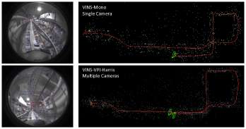
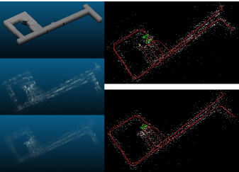
To qualitatively analyze the state estimation, the point clouds obtained by VIO are compared with the corresponding accurate 3D maps. We use the mean registration error () and the number of registered points () as the metrics to measure the VIO performance. From Table IV, we can observe that the point clouds collected by multi-camera VIO have more registered points compared with other methods. With richer point clouds, the RMSE of multi-camera VIO is still competitive to the original VINS-mono. Fig. 8 depicts an example of obtained point clouds and trajectories in Corridor.
Furthermore, we use the initialization success rate as the criterion to evaluate the robustness. We uniformly select several time points on each dataset to initialize the VIO. If the VIO can initialize within a limited time (usually 4 seconds), it is regarded as a success. For each sequence, the experiment is repeated ten times for each VIO. The results are shown in Table V. Overall, the multi-camera VIO has a remarkably higher initialization success rate compared with monocular VIO on one camera for all datasets. Especially for the Corridor dataset, the multi-camera setup improves the success rate significantly. This result shows that the multi-camera VIO is much more robust than monocular VIO on a single camera.
V CONCLUSION
In this paper, we first present a VPI enhanced front-end for visual-inertial odometry. With the efficient front-end, we propose a multi-camera VIO system with a tightly-coupled back-end. All the features observed in non-overlapping cameras are fed into the back-end for optimization. The VIO with VPI enhanced front-end reduces the CPU usage and time cost significantly, while maintains the state estimation accuracy. Without causing an extra burden on CPU and computation time, the multi-camera VIO system obtains higher robustness on system initialization and better state estimation than the monocular VIO.
In the future, we plan to incorporate the gstreamer pipeline into the multi-camera VIO. Gstreamer with VPI plugin can directly stream images from cameras to GPU and do the VIO front-end feature tracking without causing extra cost on CPU. Besides, we are also interested in enabling a brand new pose graph where scenes from different cameras can trigger the loop closure.
References
- [1] T. Qin, P. Li, and S. Shen, “Vins-mono: A robust and versatile monocular visual-inertial state estimator,” IEEE Transactions on Robotics, vol. 34, no. 4, 2018.
- [2] M. Bloesch, M. Burri, S. Omari, M. Hutter, and R. Siegwart, “Iterated extended kalman filer based visual-inertial odometry using direct photometric feedback,” The International Journal of Robotics Research (IJRR), vol. 33, no. 10, pp. 1255–1262, 2017.
- [3] R. Mur-Artal and J. D. Tardós, “ORB-SLAM2: an open-source SLAM system for monocular, stereo and RGB-D cameras,” IEEE Transactions on Robotics, vol. 33, no. 5, pp. 1255–1262, 2017.
- [4] J. Jeon, S. Jung, E. Lee, D. Choi, and H. Myung, “Run your visual-inertial odometry on NVIDIA Jetson: Benchmark tests on a micro aerial vehicle,” arXiv preprint arXiv:2103.01655, 2021.
- [5] W. Wang, D. Zhu, X. Wang, Y. Hu, Y. Qiu, C. Wang, Y. Hu, A. Kapoor, and S. Scherer, “Tartanair: A dataset to push the limits of visual slam,” in IEEE/RSJ International Conference on Intelligent Robots and Systems (IROS), 2020, pp. 4909–4916.
- [6] T. Oskiper, Z. Zhu, S. Samarasekera, and R. Kumar, “Visual odometry system using multiple stereo cameras and inertial measurement unit,” in IEEE Conference on Computer Vision and Pattern Recognition (CVPR), 2007, pp. 1–8.
- [7] T. Kazik, L. Kneip, J. Nikolic, M. Pollefeys, and R. Siegwart, “Real-time 6d stereo visual odometry with non-overlapping fields of view,” in IEEE Conference on Computer Vision and Pattern Recognition (CVPR), 2012, pp. 1529–1536.
- [8] Z. Xiang, J. Yu, J. Li, and J. Su, “Vilivo: Virtual lidar-visual odometry for an autonomous vehicle with a multi-camera system,” in IEEE/RSJ International Conference on Intelligent Robots and Systems (IROS), 2019, pp. 2486–2492.
- [9] B. Nagy, P. Foehn, and D. Scaramuzza, “Faster than FAST: GPU-accelerated frontend for high-speed VIO,” in IEEE/RSJ International Conference on Intelligent Robots and Systems (IROS), 2020.
- [10] NVIDIA. (2021) Vpi-vision programming interface documentation.
- [11] A. I. Mourikis and S. I. Roumeliotis, “A multi-state constraint Kalman filter for vision-aided inertial navigation,” in IEEE International Conference on Robotics and Automation (ICRA), 2007, pp. 3565–3572.
- [12] C. Campos, R. Elvira, J. J. G. Rodríguez, J. M. Montiel, and J. D. Tardós, “ORB-SLAM3: An accurate open-source library for visual, visual–inertial, and multimap SLAM,” IEEE Transactions on Robotics, 2021.
- [13] H. Strasdat, J. M. Montiel, and A. Davison, “Visual SLAM: Why filter?” Image and Vision Computing, vol. 30, no. 2, pp. 65–77, 2012.
- [14] J. Shi et al., “Good features to track,” in Proceedings of IEEE Conference on Computer Vision and Pattern Recognition (CVPR), 1994, pp. 593–600.
- [15] C. Harris, M. Stephens, et al., “A combined corner and edge detector,” in Alvey Vision Conference, vol. 15, no. 50, 1988, pp. 10–5244.
- [16] E. Rosten and T. Drummond, “Machine learning for high-speed corner detection,” in European Conference on Computer Vision (ECCV), 2006, pp. 430–443.
- [17] P. Liu, M. Geppert, L. Heng, T. Sattler, A. Geiger, and M. Pollefeys, “Towards robust visual odometry with a multi-camera system,” in IEEE/RSJ International Conference on Intelligent Robots and Systems (IROS), 2018, pp. 1154–1161.
- [18] M. Burri, J. Nikolic, P. Gohl, T. Schneider, J. Rehder, S. Omari, M. W. Achtelik, and R. Siegwart, “The EuRoC micro aerial vehicle datasets,” The International Journal of Robotics Research (IJRR), vol. 35, no. 10, pp. 1157–1163, 2016.
- [19] E. Rosten, R. Porter, and T. Drummond, “Faster and better: A machine learning approach to corner detection,” IEEE Transactions on Pattern Analysis and Machine Intelligence, vol. 32, no. 1, pp. 105–119, 2008.
- [20] Z. Zhang and D. Scaramuzza, “A tutorial on quantitative trajectory evaluation for visual(-inertial) odometry,” in IEEE/RSJ International Conference on Intelligent Robots and Systems (IROS), 2018.
- [21] H. Yu, W. Zhen, W. Yang, J. Zhang, and S. Scherer, “Monocular camera localization in prior lidar maps with 2d-3d line correspondences,” in IEEE/RSJ International Conference on Intelligent Robots and Systems (IROS), 2020, pp. 4588–4594.
- [22] R. Mur-Artal, J. M. M. Montiel, and J. D. Tardós, “ORB-SLAM: a versatile and accurate monocular SLAM system,” IEEE Transactions on Robotics, vol. 31, no. 5, pp. 1147–1163, 2015.