Exciton landscape in van der Waals heterostructures
Abstract
Van der Waals heterostructures consisting of vertically stacked transition metal dichalcogenides (TMDs) exhibit a rich landscape of bright and dark intra- and interlayer excitons. In spite of a growing literature in this field of research, the type of excitons dominating optical spectra in different van der Waals heterostructures has not yet been well established. The spectral position of exciton states depends strongly on the strength of hybridization and energy renormalization due to the periodic moiré potential. Combining exciton density matrix formalism and density functional theory, we shed light on the exciton landscape in TMD homo- and heterobilayers at different stackings. This allows us to identify on a microscopic footing the energetically lowest lying exciton state for each material and stacking. Furthermore, we disentangle the contribution of hybridization and layer polarization-induced alignment shifts of dark and bright excitons in photoluminescence spectra. By revealing the exciton landscape in van der Waals heterostructures, our work provides the basis for further studies of the optical, dynamical and transport properties of this technologically promising class of nanomaterials.
I Introduction
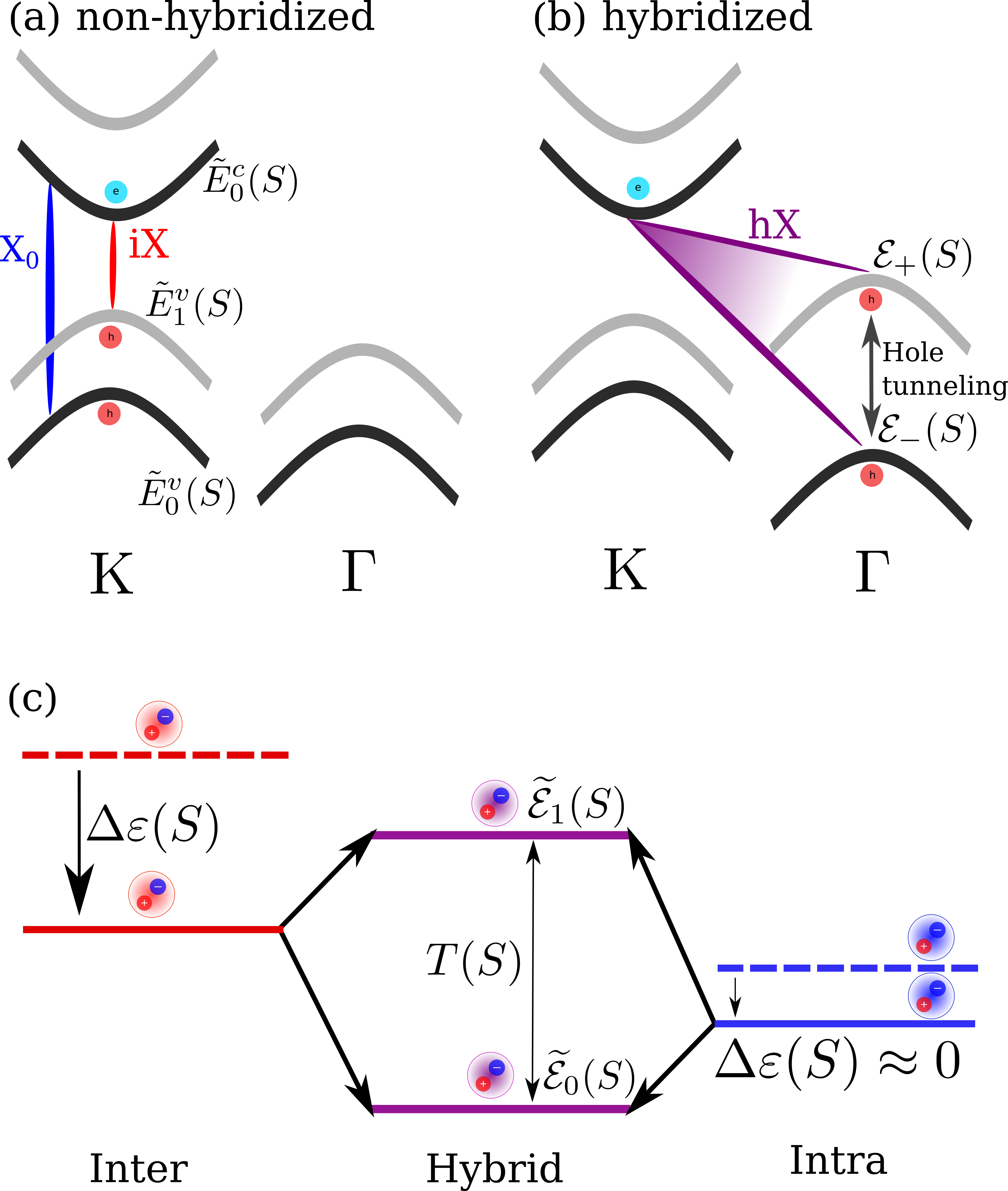
The emergence of atomically thin semiconductors has opened up a new research venue [1]. In particular, vertically stacked van der Waals heterostructures have recently gained much attention [2, 3, 4, 5], displaying intriguing fundamental properties, such as the appearance of moiré patterns and correlated states [6, 7, 8, 9, 10, 11, 12]. The transition metal dichalcogenides (TMDs) are particular promising representatives of this class of materials. Due to their strong Coulomb interaction, they harbor stable exciton features dominating optical, dynamical and transport properties of these materials even at room temperature [13, 14, 15, 16]. By vertically stacking two TMD monolayers on top of each other into a so-called van der Waals heterostructure, long-lived, spatially separated interlayer excitons can form [17, 18, 19, 20]. Through an interlayer wave function overlap, these excitons can efficiently hybridize and form new hybrid excitons [21, 22], as shown in Fig. 1. Previous studies on interlayer excitons have been conducted, focusing mostly on their optical signatures [20, 15, 23, 24, 25, 26, 27]. However, the crucial question about the spectral position and ordering of bright and dark exciton states is still debated.
In this work, we combine the density matrix formalism with density functional theory (DFT) calculations to reveal the exciton landscape for untwisted vertically stacked TMD homo- and heterobilayers. In particular, we identify the lowest lying exciton state for different TMD homo- and heterobilayers at different stackings. Furthermore, we disentangle the spectral shifts of different exciton types (Fig. 1c) stemming from hybridization and energy renormalization due to a charge polarization of the two layers (resulting in a periodic moiré potential). We find a strong impact of hybridization on momentum-dark excitons, which can turn them into the energetically lowest states and the material into an indirect semiconductor. We also analyze the optical footprint of the exciton landscape by calculating photoluminescence (PL) spectra and taking into account direct and phonon-assisted exciton recombination. The latter allows an indirect visualization of dark excitons via the emergence of phonon sidebands [28]. This allows us to identify the microscopic origin of resonances appearing in PL spectra of different TMD homo- and heterobilayers at different stackings.
II Theory
We exploit the exciton density matrix formalism [29, 30, 31] with input from DFT to construct a material specific fully microscopic framework for modeling the exciton energy landscape in van der Waals heterostructures. The goal is to disentangle the microscopic contributions from hybridization and layer polarization-induced alignment shifts, to the final energies of hybrid excitons, as illustrated in Fig. 1.
We start by formulating a many-particle Hamilton operator in second quantization. The interaction-free electronic Hamiltonian for vertically stacked TMDs consists of three parts , where is the stacking-independent kinetic energy. The renormalization Hamiltonian describes the stacking-dependent layer polarization-induced alignment shift [12, 32]. In the following, we refer to this as the alignment shift. Finally, is the hybridization Hamiltonian taking into account the overlapping electronic wavefunctions giving rise to hybrid exciton states. In the basis of monolayer eigenstates, the bilayer Hamiltonian thus reads
| (1) |
where / are layer indices while is a compound index with denoting the valley and the conduction and the valence band, respectively. The goal of this framework is to explicitly take into account dark intervalley exciton states [33]. Here, we have introduced the electronic creation (annihilation) operators . Furthermore, includes the stacking-independent kinetic energy of the monolayers () and the alignment shift ().
Finally, is the tunneling matrix element, where the stacking dependence () results from the varying interlayer distance and orbital symmetry of the Bloch functions involved. For the K point, the conduction and valence band Bloch waves are composed of d-orbitals [32, 34, 35]. Using the angular symmetry of d-orbitals, the tunneling around the three equivalent K points in an untwisted structure can be written as [32]
| (2) |
where denotes the three-fold rotation operator and the stacking dependent lateral displacement between the layers. Furthermore, describes the tunneling strength and is a prefactor which equals for the K and for the K′ point. The factor reflects that the three equivalent K points have the same tunneling strength. For H-type structures, this expression obtains the additional phase for the valance band [32].
Due to symmetry, tunneling can only occur for certain stacking configurations. To demonstrate this effect, we first consider tunneling around the K point for R-type structures (schematically shown in Fig. 3c) and apply the corresponding lateral displacement vectors for each high-symmetry stacking. We find that the tunneling term vanishes for and around the K point [36]. For an H-type structure one of the two layers is inverted (rotated by ) relative to the R-structure. Here, the tunneling for both electrons and holes vanishes at . In addition, hole (electron) tunneling does not occur at (). This means that we only have a non-zero tunneling matrix element at the K point for , (electron tunneling) and (hole tunneling) stacking. In these cases, Eq. 2 simply becomes .
For tunneling around the and points, there are no equivalent points within the first Brillouin zone (BZ) and thus the tunneling matrix element is only given by the tunneling strength [32]. The latter can be extracted from DFT calculations of the bilayer band structure by considering the Hamiltonian in Eq. 1 as a matrix with respect to the layer index /. Here, the diagonal components are given by and the off-diagonal terms correspond to the tunneling . The eigenvalues of this matrix are given by the avoided-crossing formula
| (3) |
where is the spectral difference between the monolayer energies as extracted from DFT calculations shifted by the layer polarization-induced alignment potential, sometimes referred to as the ferroelectric potential [37] (Fig. 1a). Furthermore, is the tunneling strength (see Eq. 2) and are the hybrid energies corresponding to the bilayer eigenenergies extracted from DFT calculations. As illustrated in Fig. 1b, the hybridization is particularly prominent at the point due to the strong tunneling probability of holes. In contrast to the bands at the K point, which are mostly composed of d-orbitals localized around the metal atom, the bands at the point also have a significant contribution from chalcogen atoms, thus considerably increasing the interlayer overlap [35, 38, 22]. Exploiting Eq. 3, the tunneling strength can be calculated for each band, valley, and stacking, yielding
| (4) |
where is the spectral difference between the hybridized electronic states.
To obtain a microscopic picture of the energy landscape in van der Waals heterostructure, we performed DFT calculations. First, we relax the investigated TMD homo- and heterobilayers using VASP [39, 40, 41]. The vdW-DF-cx functional [42] is used to account for the van der Waals interactions of the bilayers. The plane wave energy cutoff is 500 eV and the BZ is sampled using a point mesh. The electron density of the relaxed structures is subsequently evaluated using the local density approximation in GPAW [43, 44] with a grid spacing of 0.15 Å. The alignment shift stems from a charge transfer induced dipole moment [45]. Its origin, the electrostatic potential is calculated by solving the Poisson equation. The alignment shifts can then be found within the project augmented wave formalism (Appendix A). Exploiting the computed monolayer energies (), alignment shifts () and the hybrid bilayer energies (), the tunneling strength can be calculated from Eq. 4. The values are summarized for several homo- and heterobilayers in the appendices.
Having obtained both the alignment shifts and the tunneling-induced hybridization, we investigate now the impact of these microscopic processes on the final exciton energy. To achieve this goal, we transform the Hamiltonian in Eq. 1 into an exciton basis resulting in [30, 12, 32],
| (5) |
Here, and are compound layer and valley indices, the first labeling the two intra- and interlayer excitons respectively and the second labeling the valley configuration. The index denotes the stacking and the center-of-mass momentum. Furthermore, is the exciton creation (annihilation) operator and is the exciton tunneling matrix element, which takes into account the tunneling strength and exciton form factors. The energy is the exciton energy associated with the binding energy, the stacking-independent monolayer band edges and the alignment shift. The completely stacking-independent part of this energy, i.e. without considering the alignment shifts, yields the unperturbed exciton energies (the dashed lines in Fig. 1c). The interlayer and intralayer exciton binding energies are microscopically obtained by solving the Wannier equation , where the strong Coulomb interaction between electrons and holes is taken into account. Furthermore, the screening of the Coulomb potential is modeled with the generalized Keldysh screening [46]. The change in interlayer distance does in principle affect the screening, but since the variation in distance is small, this effect has an negligible impact on the binding energy.
The four different intra- and interlayer exciton states couple to each other through hybridization and split into four hybrid exciton states. The final hybrid exciton operator can be written in terms of a linear combination of the composing intra- and interlayer excitons i.e. , where is the hybrid exciton quantum number. The mixing coefficient fulfills the eigenvalue problem
| (6) |
Here, denotes the final hybrid exciton energies. Equation (6) provides microscopic access to the exciton landscape in different TMD homo- and heterobilayers, allowing us in particular to identify the energetically lowest exciton state for different stackings.
III Results
III.1 Exciton energy landscape
The final hybrid exciton energies are obtained by solving the eigenvalue problem in Eq. 6. We use the calculated tunneling strengths and alignment shifts, where the effective masses and valley separations are described in a monolayer basis [47]. This also yields the respective degree of hybridization for each exciton valley (K-K, K-K′, K-, -K, -K′, -). As an exemplary material, we first investigate the untwisted MoS2-WS2 heterostructure on a SiO2 substrate. The latter is taken into account via a substrate screening of the Coulomb potential.
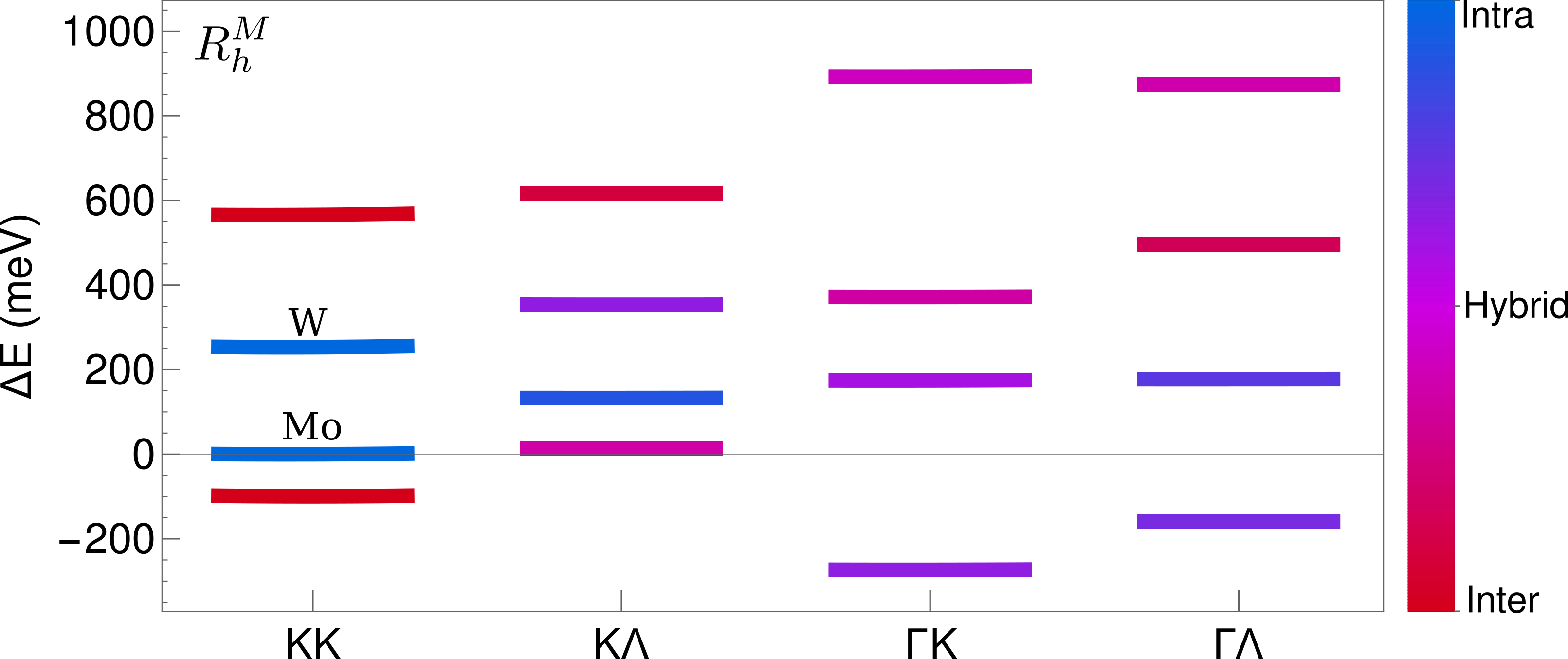
In figure 2, the lowest lying exciton state for all layer configurations at the -stacking is displayed. It is evident that the -K exciton is clearly the energetically lowest state. It is located about 300 meV below the lowest bright A exciton (intralayer K-K in MoS2). Its purple color indicates that the -K exciton is strongly hybridized reflecting a strong hole tunneling. The lowest lying K-K state is an interlayer exciton (red color).
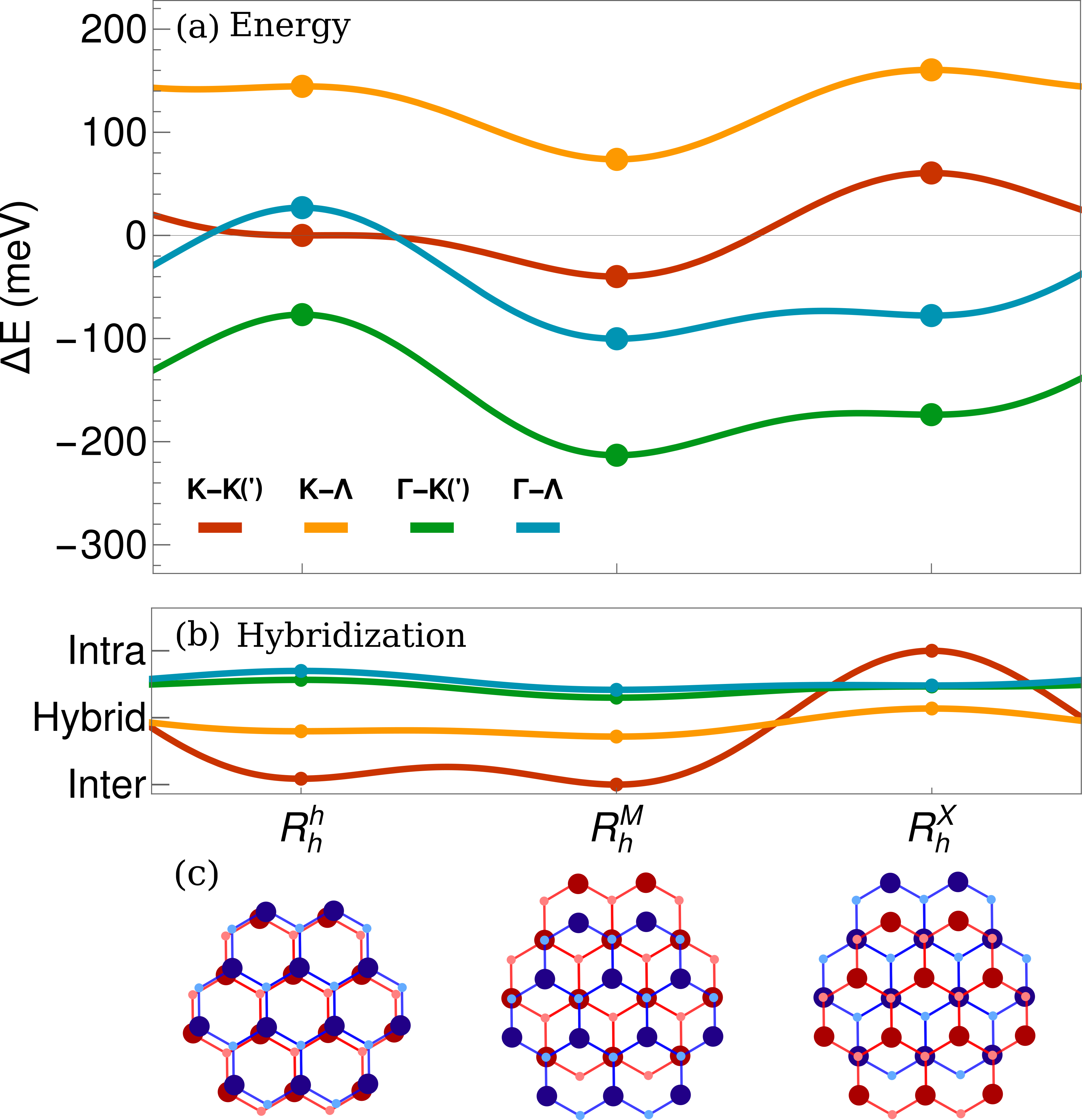
Figure 3a illustrates the lowest lying exciton state for each exciton valley as a function of stacking, while Fig. 3b shows the corresponding degree of hybridization. Energies and coefficients were computed for the three high-symmetry stackings (circles in Fig. 3a,b), whereas intermediate displacements have been interpolated with the fit function given in Appendix A. We predict that the -K(′) excitons are the lowest lying states regardless of stacking. Note that the -K′ exciton is about 1 to 5 meV lower than the -K state, this is mainly due to the slightly increased effective mass at the K′ point compared to that of the K point. Furthermore, we find that the lowest K-K transition is given by interlayer excitons, except for the -stacking, where the intralayer exciton gives the largest contribution to the lowest lying K-K exciton. The K- exciton, although very strongly hybridized, is located about 100 meV above the K-K exciton for all stackings. This is mostly due to the large energy difference between the and the K point band edges in MoS2. The - exciton interestingly exchanges place with the K-K exciton, at compared to . This can be ascribed to the change in interlayer distance, which strongly affects the hybridization and has been implicitly taken into account in the energies extracted from our DFT calculations as in the latter we allowed for relaxation of the interlayer spacing.
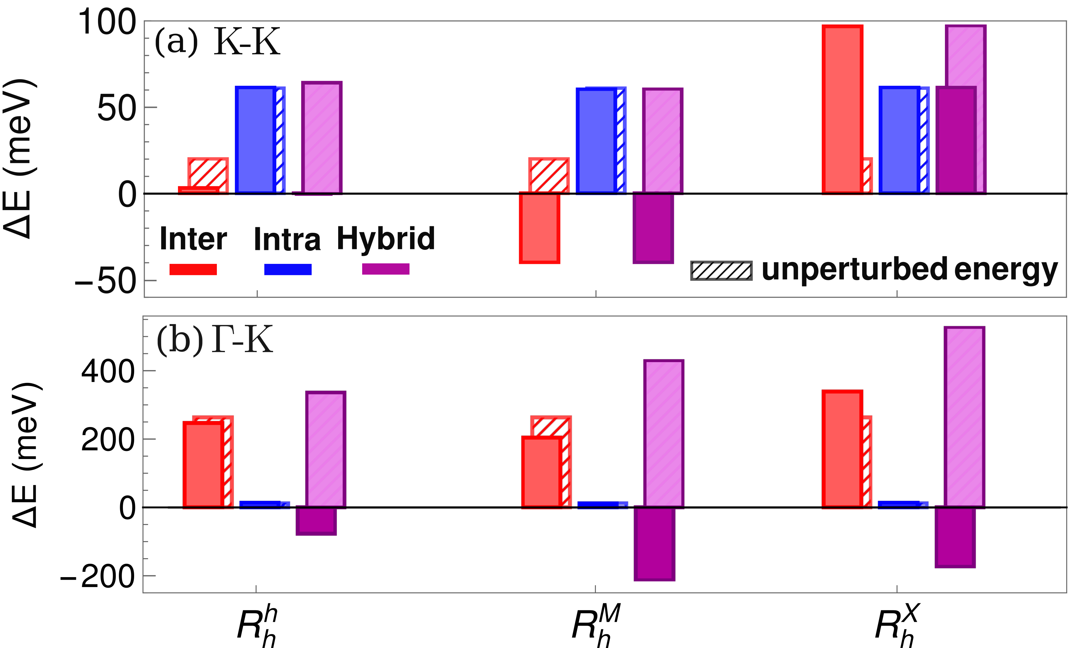
By turning on and off certain parts of the Hamiltonian in Eq. 5) and consequently modifying the eigenvalue problem in Eq. 6, we can now disentangle the relative microscopic effects of hybridization and alignment shifts. Figure (4) resolves these contributions for K-K and -K excitons at various R-type stackings in MoS2-WS2. Here, the red (blue) hatched bars indicate the lowest lying unperturbed interlayer (intralayer) exciton and the filled red bar, the lowest lying interlayer (intralayer) exciton after applying the alignment shifts. The two purple bars display the energetic position for the two final hybrid exciton states including the effect of hybridization.
| -K(′) | K-K(I) | -K(′) | K- | K-K | K- | |||||||||||||
| -K(′) | K-K(I) | -K(′) | - | K- | K- | |||||||||||||
| -K(′) | K-K | -K(′) | - | K- | K- | |||||||||||||
| -K(′) | K- | -K(′) | - | K- | K- | |||||||||||||
| -K(′) | K-K′ | -K(′) | - | K-K | K- | |||||||||||||
| -K(′) | K-K′ | -K(′) | - | K-K | K- | |||||||||||||
We first focus on the microscopic contributions of hybridization and alignment shifts for the K-K exciton (Fig. 4a). We find that the interlayer exciton is the energetically lowest state at and stacking (red bar). This is due to the large band offset between the layers (Fig. 1a) and the alignment red-shift. Rather unexpectedly at , the intralayer exciton becomes the energetically lowest state (blue bar). Here, the metal atoms of the upper layer (WS2) are on top of the chalcogen atoms of the bottom layer (MoS2) (Fig. 3c). This variation in atomic configuration leads to a change in direction of the layer polarization field, thus changing the nature of the energy shift relative to . As a result, the lowest lying interlayer exciton becomes blue-shifted — opposite to the red-shift for the stacking (solid vs hatched red bar), where the chalcogen atoms of the upper layer (WS2) are on top of metal atoms of the bottom layer (MoS2) (Fig. 3c). This blue-shift is large enough to compensate for the otherwise large band offset between the layers, thus making the intralayer exciton the lowest lying state. However, this effect is difficult to observe in PL experiments due to the small oscillator strength of the interlayer exciton and the overall dominant nature of -K excitons in MoS2-WS2 (Fig. 3a). In addition, we observe that the K-K exciton is only very weakly affected by hybridization at and not at all at stacking (compare the purple bars with red and blue bar, respectively). The vanishing tunneling at is enforced by the orbital-symmetry of the states at the K point (Eq. 2). As a result, the variation in the energy for the K-K exciton is only due to the alignment shift.
Considering the situation for the -K exciton in Fig. 4b, we immediately observe the significant role of hybridization that is reflected in the large red-shift of the dark purple bars. This is expected due to the strong tunneling of holes at the point. The strong variation in energy between different stackings for the hybrid -K exciton mainly results from the varying interlayer distance, which has a strong impact on the tunneling strength (see Eq. 4). However, also the stacking-dependent layer polarization field changes the energetic distance of the initial intra- and interlayer states and therefore indirectly influences the hybridization process.
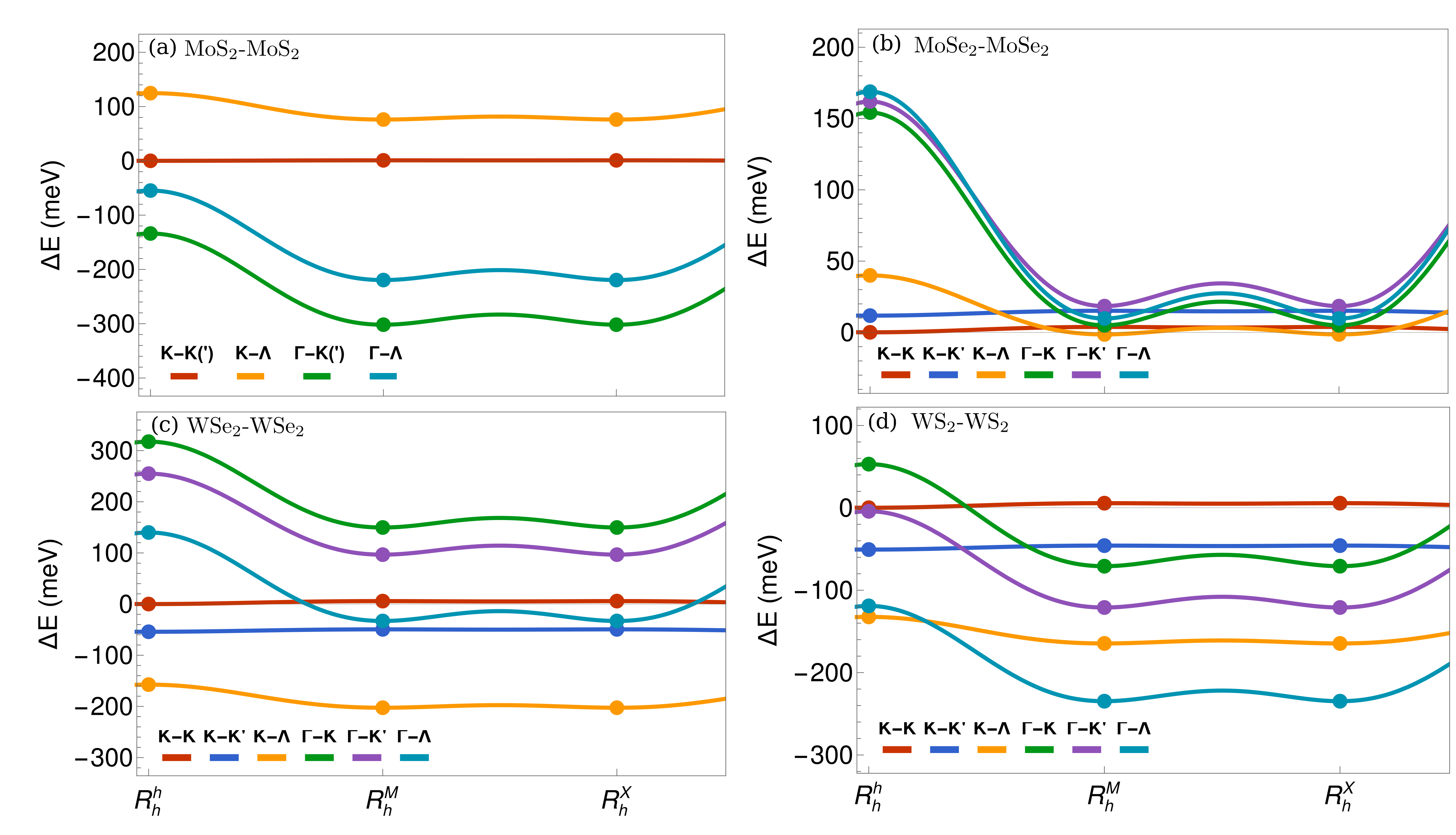
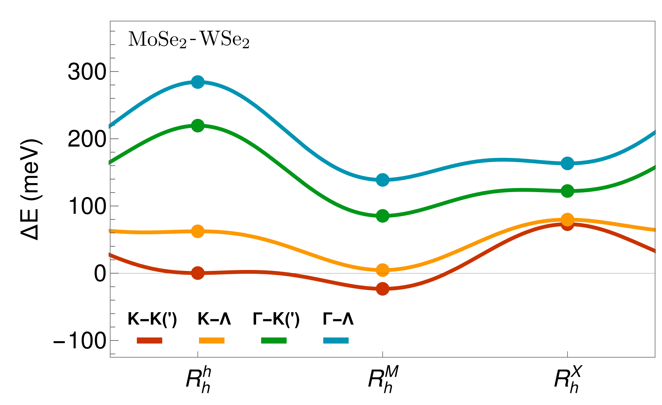
We performed calculations for multiple TMD homo- and heterobilayers mapping out their entire exciton energy landscape. The results are summarized in Table 1 including the lowest lying exciton for each material and stacking and its energetic distance to the bright K-K exciton. In the MoS2-WS2 heterostructure, we predict the momentum-dark -K(′) exciton to be the lowest regardless of stacking. The situation is completely different in MoSe2-WSe2, where the bright K-K exciton is the lowest in R-type stacking, the K- exciton in and the K-K′ exciton in -stacking. Interestingly, the K- exciton becomes the lowest due to the increased tunneling strength with the varying interlayer distance, while the K-K′ exciton is the lowest due to the nature of the H-type stacking, where the spin ordering changes in one of the layers. This means that the K-K′ exciton in H-type structures corresponds to K-K excitons in R-type stackings [36]. For TMD homobilayers, and are equivalent stackings just mirrored in the out-of-plane direction. Similarly to MoS2-WS2, the -K(′) exciton is also the lowest state in MoS2-MoS2 bilayers due to the strong tunneling of holes around the point. In contrast, in WSe2-WSe2 the K- exciton is the lowest reflecting the efficient tunneling of electrons at the point, whereas the -valley cannot compete due to the large energy separation to the K point in the monolayer case. Interestingly, we find a different lowest exciton in WS2-WS2 depending on the stacking: K- exciton at the -stacking and - exciton at and , where the interlayer distance is reduced resulting in a larger red-shift of the - exciton due to the hybridization.
III.2 Photoluminescence
So far we have been focusing on exciton energies in TMD homo- and heterobilayers revealing a rich landscape of various direct and indirect excitons. Now we investigate the optical response of these excitons by calculating PL spectra. In particular, we take into account direct and indirect recombination of excitons, the latter driven by emission and absorption of optical and acoustical phonons. To this end, we exploit the generalized Elliot formula for phonon-assisted PL derived in Refs. [28, 32] reading
| (7) |
where is the hybrid exciton quantum number, the polarization of the photon, the valley index, the involved phonon momentum, the phonon mode and denotes phonon absorption () and emission (). The first part of the equation describes the direct recombination of bright excitons within the light cone at the K point. Here, is a Cauchy–Lorentz distribution and is the exciton-photon matrix element determining the oscillator strength of the hybrid excitons. Furthermore, is the hybrid exciton energy as calculated by the eigenvalue problem given in Eq. 6. The radiative and non-radiative broadening are described by and , respectively. Since this work mainly focuses on the spectral position of the peaks, we account for these phenomenologically (Appendix D).
After optical excitation, excitons distribute throughout different valleys according to the Boltzmann distribution . By emitting or absorbing a phonon, momentum-dark excitons can become optically visible via (indirect) phonon-assisted recombination or in pump-probe spectra [48]. This higher-order process is determined by the second part of Eq. 7, where is the exciton-phonon matrix element that takes into account the electron-phonon coupling deformation potentials (Appendix D) [49, 50]. Furthermore, denotes the phonon energy and the phonon occupation, which is given by the Bose-Einstein distribution . In this equation we have neglected the unlikely higher-order process involving two phonons, which would be needed to scatter the - exciton to the bright K-K state.
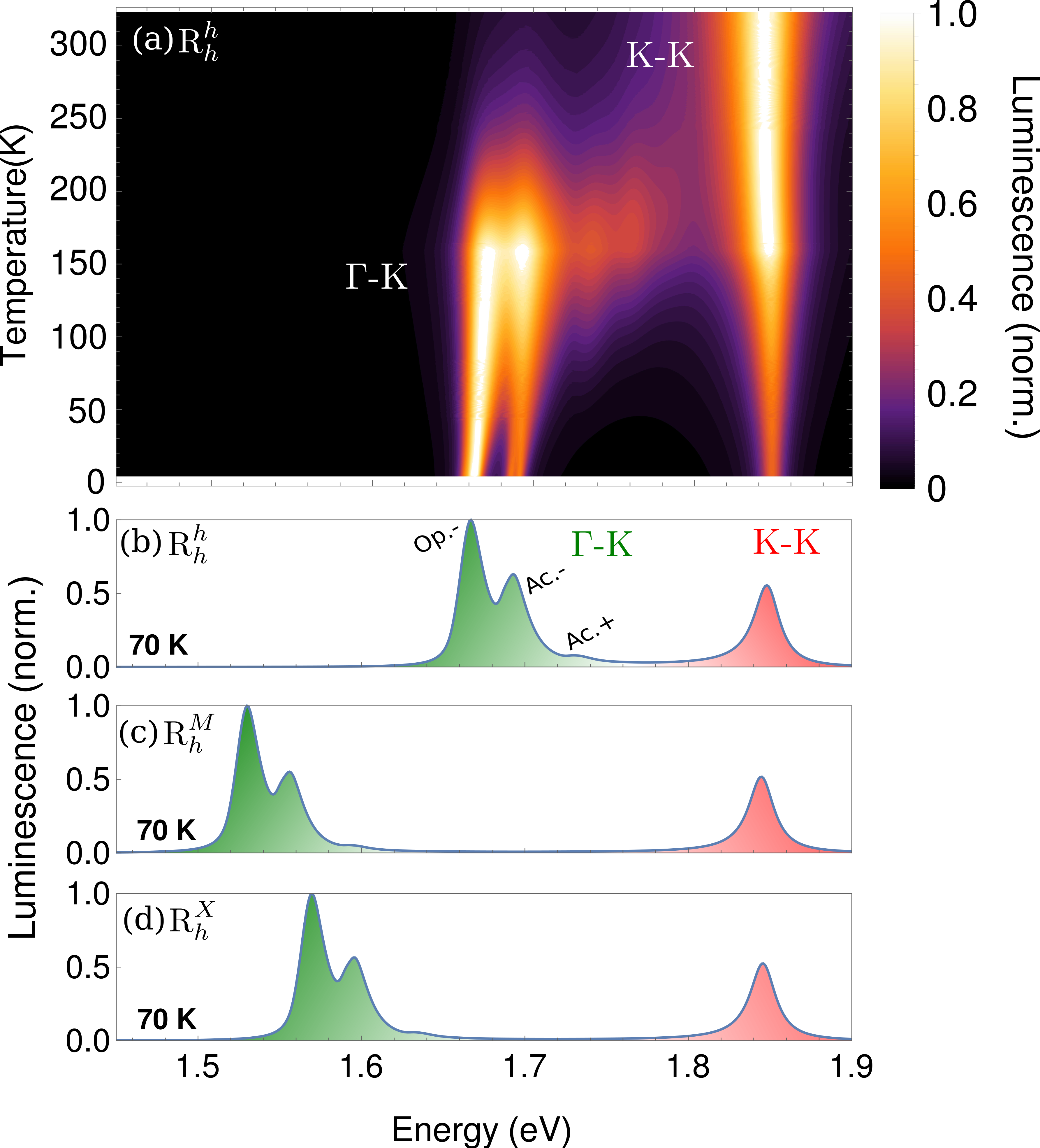
By evaluating Eq. 7 numerically for different TMD bilayers at various temperatures, we reveal the optical footprint of the exciton landscape for different materials at different stackings. Figure 5a shows the temperature-dependent PL in the exemplary case of MoS2-WS2 in stacking. Here the position of the A exciton is fixed to experimental values [23]. PL spectra from other TMD homo- and heterobilayers for different stackings are shown in the appendices. We find that at higher temperatures, the bright K-K exciton dominates the PL, while at lower temperatures, phonon sidebands from the -K exciton become pronounced. They stem from emission of acoustical and optical phonons and are clearly separated at very low temperatures, while they overlap at intermediate temperatures reflecting the increased non-radiative broadening. In the temperature range around 150 K, we find the emergence of additional peaks stemming from phonon absorption. We can also see a clear asymmetrical broadening of the peaks at higher temperatures. This is due to the Boltzmann nature of the exciton distribution and is characteristic for the appearance of phonon sidebands.
To further understand the nature of the multi-peaked PL, we show the PL at 70 K at different stacking in Fig. 5b-d. We identify the peak with the highest intensity as a phonon sideband stemming from the emission of an optical phonon. The next highest peak can be traced back to the emission of an acoustical phonon. These peaks have about equal contribution from their respective transverse and longitudinal components. There is a slight variation in the relative intensity of these peaks with stacking. This is due to the weak change in the degree of hybridization (Fig. 4b), which means that the phonon contributions from each layer will be weighted differently. A small peak stemming from the acoustical absorption phonon mode is also visible at higher energies. The PL at the three different stackings is qualitatively the same. We observe a clear stacking-dependent red-shift of the phonon sidebands reflecting different hybridization of the -K exciton (Table 1).
Our results are in good agreement with experiments, where two predicted phonon sidebands have been observed about 300 meV below the bright K-K exciton in MoS2-WS2 [23]. This corresponds well to the calculated PL at - and -stacking, which is the energetically most favorable R-type stackings. The relative intensity of the two predicted phonon sidebands favoring the lower one agrees well with the experimental observation. An indirect dark exciton has also been observed in MoS2-MoS2 [24, 51] and WSe2-WSe2 [27, 51] located about meV and meV below the bright exciton, respectively - in a very good agreement with our results summarized in Table 1. Similar observations have been made also for WS2-WS2 including a peak roughly meV below the K-K exciton [26]. This is in good agreement with the predicted phonon sideband from the K- exciton in our calculations. Overall, our work provides microscopic insight into the exciton landscape and the optical signatures for a variety of TMD bilayers. In particular, the energy landscapes obtained for different lateral displacements play an important role for the understanding of the spatially dependent stacking domains and resulting moiré potentials [52, 53] in twisted van der Waals bilayers.
IV Conclusion
We have presented a material specific and fully microscopic model revealing the exciton landscape in TMD homo- and heterobilayers at different high-symmetry stackings. We identified the energetically lowest lying exciton state for each respective material and stacking. By combining the exciton density matrix formalism and density functional theory, we have gained microscopic insights into different contributions determining the hybrid exciton states including tunneling-induced hybridization and layer polarization-induced alignment shifts. Finally, we predict the optical footprint of the calculated exciton landscape in photoluminescence spectra including direct and phonon-assisted indirect exciton recombination processes. This allows us to uncover the exciton type behind the most prominent resonances for different TMD bilayers at different stackings. Furthermore, revealing the energy landscape at different stackings gives us insight into the expected behavior of the moiré potential at high-symmetry points in a twisted structure. Presenting the exciton landscape and its impact on optical spectra, our work can guide future theoretical and experimental studies in the growing field of van der Waals heterostructures.
Acknowledgments
This project has received funding from Deutsche Forschungsgemeinschaft via CRC 1083 (project B09), the European Unions Horizon 2020 research and innovation programme under grant agreement no. 881603 (Graphene Flagship) as well as the Swedish Research Council (2018-06482, 2020-04935). Furthermore, we acknowledge the support from the Knut and Alice Wallenberg Foundation via the grant KAW 2019.0140 and Vinnova via the competence centre “2D-TECH”. The computations were enabled by resources provided by the Swedish National Infrastructure for Computing (SNIC) at PDC and NSC partially funded by the Swedish Research Council through grant agreement no. 2018-05973.
Appendix A: Layer polarization-induced alignment shift
The matrix elements governing the layer polarization-induced alignment shift of the single particle states are given by
| (8) |
They were computed within the PAW formalism, where is the orbital density of the state in the monolayer . Here, is a compound index containing as the band index and as the valley index. To this end, is the solution to the Poisson equation for the electron density difference with , with the subscript indicating the layer. Band renormalizations and monolayer energies, i.e (see Eq. 1), are extracted from DFT calculations for various homo- and heterobilayers and are summarized in Table 3 for R-type structures and in Table 4 for H-type structures. The indices and have been dropped from the alignment shift , since the latter is a valley-independent energy renormalization of the entire band structure. The intermediate displacements have been interpolated with a continuous fit function given by [12],
| (9) |
where is the stacking-independent monolayer energy and for H-type stacking, otherwise . Furthermore, and determine the stacking-dependent shift. These parameters are fitted to the band structure for the K point, obtained from first-principle calculations , where the momentum , i.e the minimum of the parabolic dispersion. For the correct energetic position of other valleys, one has to take into account the spectral valley separation and spin orbit splitting Ref. [47] listed in Table 2. The fitted parameters for all materials can be found in Tables 5 and 6. The tunneling strength as expressed in Eq. 4 in the main part of the manuscript is given in Table 7 for different homo- and heterobilayers.
Appendix B: Exciton Hamiltonian
We transform the Hamilton operator given in Eq. 1 into an exciton basis [32, 12]. For this purpose, we expand the electronic creation and annihilation operators in pair operators in the low density limit (with as a compound index) yielding
| (10) |
This allows us to expand the Hamiltonian in center-of-mass coordinates, using the exciton operators [30, 32] yielding
| (11) |
Here, is the exciton quantum number, which we set to 1s, since we are focusing on the lowest lying exciton states. Furthermore, is the exciton wavefunction as obtained from the solution of the Wannier equation [46]. Here, we have introduced and . This consequently results in an exciton Hamiltonian
| (12) |
where is the center-of-mass momentum, the exciton valley index and a compound index replacing the generic indices . Here, we have assumed an untwisted structure and thus no momentum transfer is involved. The tunneling matrix element is given by
| (13) |
The matrix elements for the conduction and valance band are described in the main part of the manuscript. Finally, the exciton form factors are given by
| (14) |
By expanding the exciton Hamiltonian into hybrid exciton operators, we can derive an eigenvalue problem, which diagonalizes the Hamiltonian and yields the final hybrid exciton energies as shown in the main text.
Appendix C: Exciton energy landscape
Here, we discuss the exciton energy landscape for the four homobilayers MoS2, WS2,WSe2, MoSe2 and the heterostructure MoSe2-WSe2 that have not been covered in the main text. Figure 6a shows the exciton landscape for for the three R-type high-symmetry stackings. Similar to the heterostructure discussed in the main text, in this homobilayer -K exciton is the energetically lowest state for all stackings. The - exciton is also significantly red-shifted, but due to the large valley separation of the point, it still remains above the -K exciton.
| K | -462 meV | -184 meV | -425 meV | -148 meV |
|---|---|---|---|---|
| K | -37 meV | 22 meV | -31 meV | 3 meV |
| -5 meV | 163 meV | 27 meV | 246 meV | |
| -506 meV | -329 meV | -269 meV | -46 meV |
The exciton landscape for the homobilayer is illustrated in Figure 6b. Here, we can see that the K-K exciton is the lowest at , while K- becomes the lowest at and . This reflects the increased tunneling probability of electrons when the interlayer distance decreases at the latter two stacking configurations.
In the homobilayer shown in Fig. 6c, we can instead see that the K- exciton is the lowest state. This is mostly due to the very strong tunneling of electrons around the point. In , the point is very far away from the global valence band maximum and even though it has a larger tunneling strength than at the point (see Table 4), the associated -K/ excitons remain above K- states. Due to the significant spin-orbit splitting in the conduction band at the K point, we have also included the K′-related excitons.
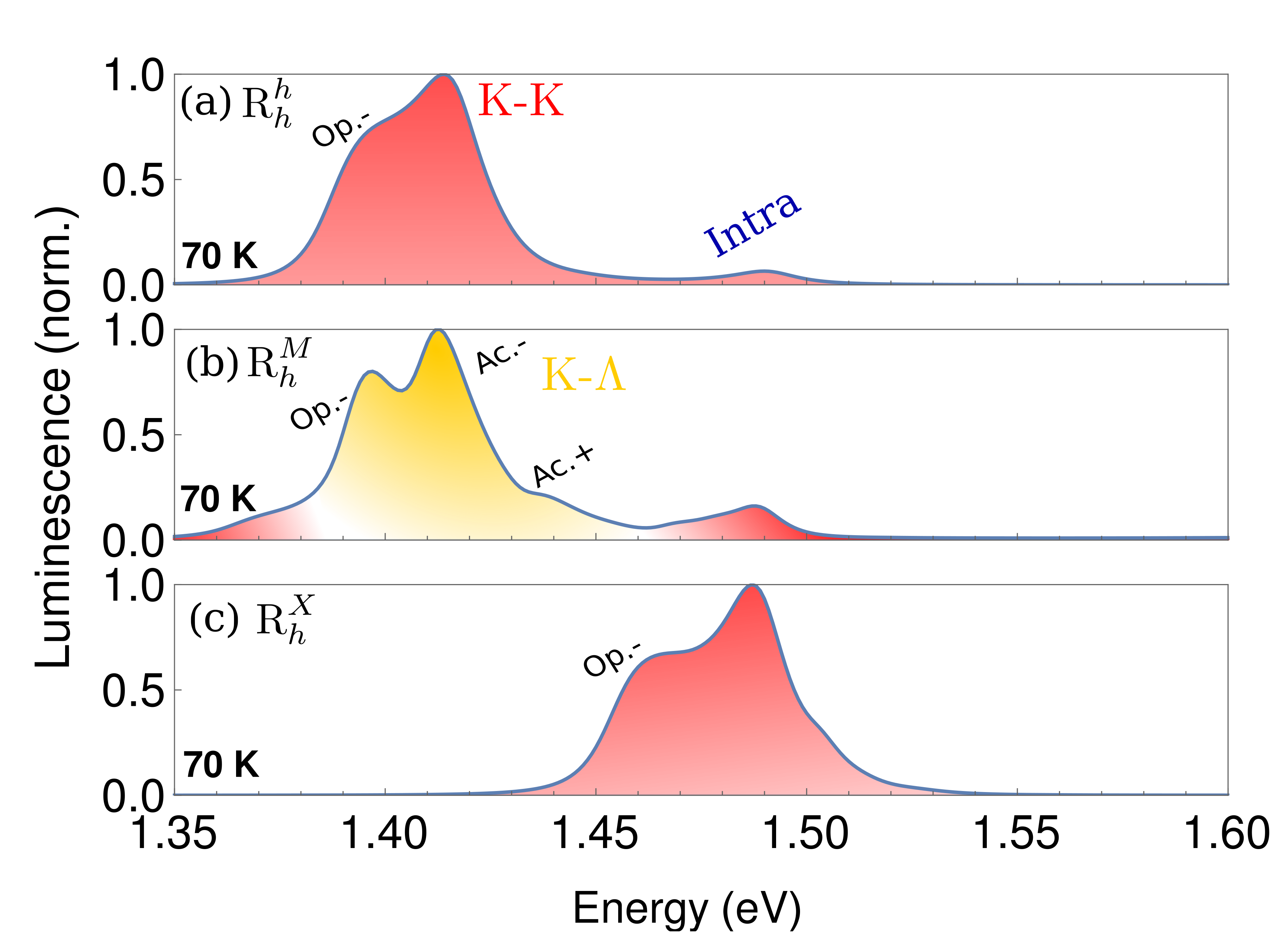
Figure 6d illustrates the stacking-dependent exciton energies for the homobilayer. Here, we find that - excitons are the energetically lowest states. In this material, the () point of the monolayer is energetically much closer to the valence (conduction) band edge at the K point. Consequently, considering the strong hybridization in these valles, the - exciton becomes by far the lowest lying exciton in -stacking. However, we observe that at stacking, the K- is the lowest state instead. This is due to the increased interlayer distance at these stackings.
For the four homobilayers discussed above, we can see no change between the and -stacking, since these stackings are mirror-symmetric for a homobilayer. We also observe a very strong hybrid nature for the low lying dark excitons (-K, -, K-) in comparison to the heterostructure discussed in the main part. This is mostly due to the lack of a band offset in homobilayers, which consequently reduces the detuning of the intra- and interlayer exciton and thus enhances the layer mixing.
In figure 7 the exciton landscape for the heterostructure is shown. In contrast to , which is discussed in the main part of the manuscript, the K-K exciton is the lowest lying exciton, regardless of stacking. This is mainly due to the large valley separation for (see Table 2) and the large band offset between the different materials. We can also see that the K- exciton lies very close to the bright K-K exciton, especially at and stackings.
Appendix D: Photoluminescence spectra
As described in the main part of the manuscript, the photoluminescence (PL) spectra are calculated by considering both the resonant emission of photons from excitons and phonon-assisted recombination of excitons as a higher-order process. The exciton-photon matrix element which governs the direct photoemission reads [28, 32],
| (15) |
where is the oscillator strength and the square root of the radiative decay rate [5]. Furthermore, ensures that only bright excitons are taken into account in the completely resonant case.
For the indirect, phonon-assisted exciton recombination, the exciton-phonon matrix element plays the crucial role and is given by [28, 32]
| (16) |
Here, is the mixing coefficient and it holds for untwisted structures, since the mixing coefficient only weakly vary due to similar masses of intra- and interlayer excitons. The transferred valley momentum ensures the correct transformation between the globally defined phonon momentum and the exciton/electron momenta defined in valley local coordinates. The selection rule enforces that electron-phonon scattering takes place within one monolayer and that no tunneling occurs during this process. This assumption holds, as the interlayer atomic interaction is given by the van der Waals interaction, which is very weak in comparison to the in-plane atomic bonds. As a result, it is highly unlikely for phonons to tunnel during this process. The exciton-phonon matrix elements for the conduction and valance band are given by [28, 32],
| (17) |
Here, are the electron-phonon coupling deformation potentials, calculated via ab-inito calculations in [49, 50]. The intravalley scattering with acoustic phonons is approximated as linear in momentum, otherwise the coupling is given by a constant. Similarly the phonon dispersion in Eq. 7 in the main text is approximated as a constant (according to the Einstein model), while the long range acoustic phonons (intravalley scattering) are approximated as linear in momentum (Debye model). The values for the phonon dispersion is also calculated via ab-inito calculations in [49, 50].
The radiative and non-radiative broadening of the exciton resonances are treated phenomenologically. The non-radiative broadening is approximated with a linear temperature dependence in accordance with Ref. [54, 32] with and . The non-radiative broadening of dark excitons is significantly smaller, since they are lower in energy and therefore have less relaxation channels for scattering with phonons.
In Fig. 8, the Pl spectra for the heterostructure MoSe2-WSe2 is illustrated. Here we can see that the spectra is dominated by the bright K-K exciton at the and stacking. At we also observe a small peak from the A exciton. A special case arises when considering -stacking: The lowest lying exciton is the interlayer K-K exciton, but due to its weak oscillator strength, the PL is dominated by the K- exciton instead.
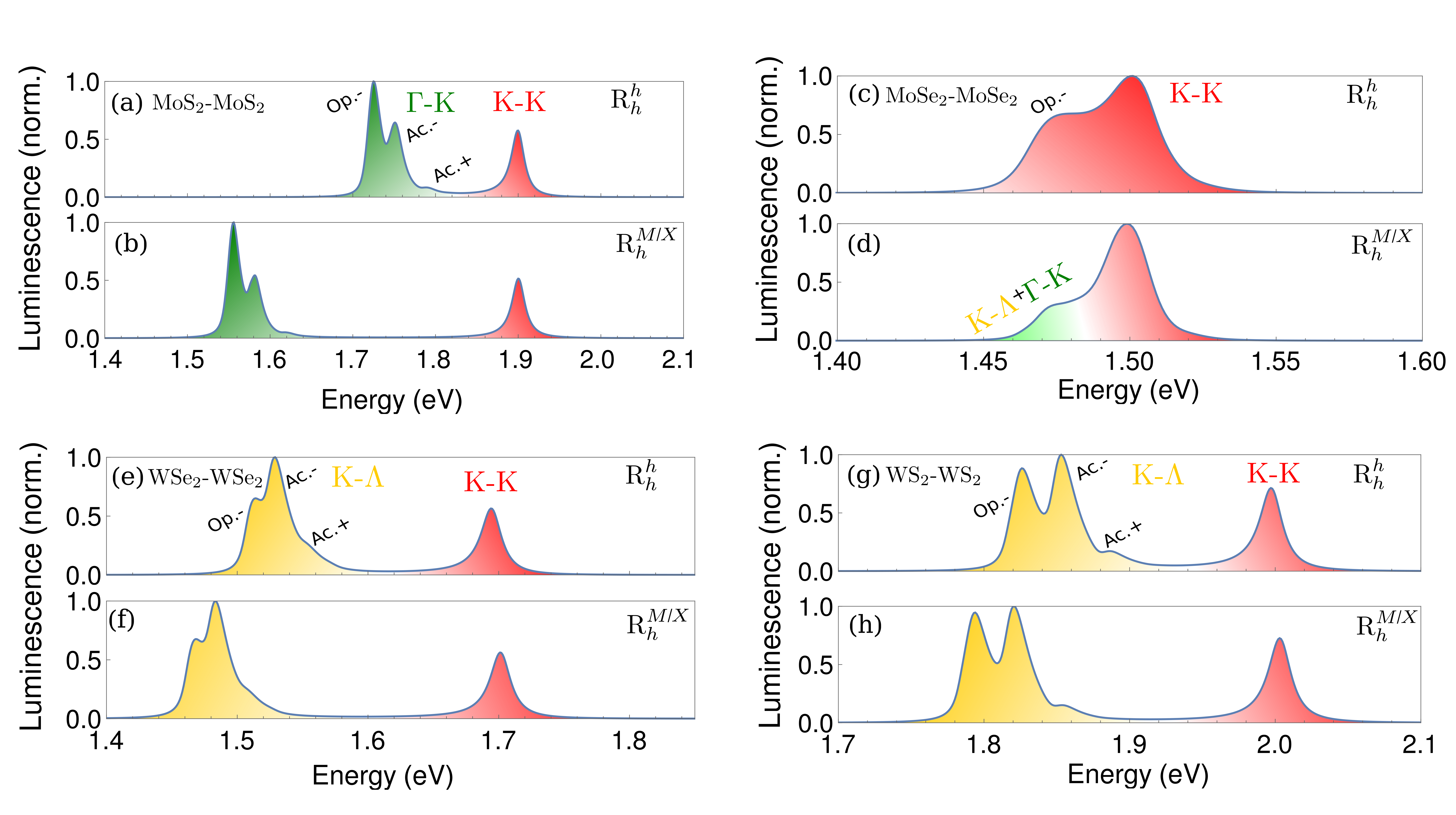
Figure 9a-h show the PL spectra for the four homobilayers (MoS2-MoS2, WSe2-WSe2, WS2-WS2, MoSe2-MoSe2) for different stackings. The spectrally lowest -K and K- resonances are marked green and yellow, respectively. We observe that these momentum-dark excitons clearly dominate the PL at 70 K for MoS2-MoS2, WSe2-WSe2 and WS2-WS2. In the case of WS2-WS2, the actually lowest - exciton is not visible, since here an unlikely two-phonon process is required for the indirect exciton recombination. In the case of MoSe2-MoSe2, the bright K-K exciton dominates with a low-energy shoulder stemming from the momentum dark -K and K- excitons at and stackings.
| K-Mo(v) | -6157.1 meV | 7.7 meV | -14.1 meV | 52.9 meV | |
| K-W(v) | -5932.5 meV | -8.3 meV | 10.4 meV | -58.1 meV | |
| K-Mo(c) | -4371.3 meV | 6.8 meV | -15.7 meV | 52.8 meV | |
| K-W(c) | -3984.3 meV | -9.2 meV | 9.6 meV | -60.3 meV | |
| K-Mo(v) | -5555.1 meV | 10.5 meV | -6 meV | 46.5 meV | |
| K-W(v) | -5341.3 meV | -11.5 meV | 1.8 meV | -51.6 meV | |
| K-Mo(c) | -3994.8 meV | 9.5 meV | -8.1 meV | 46.7 meV | |
| K-W(c) | -3646.7 meV | -12.7 meV | 1.1 meV | -54.3 meV | |
| K-L1(v) | -6156.9 meV | -0.2 meV | -35.8 meV | 31.6 meV | |
| K-L2(v) | -6156.9 meV | -0.2 meV | 31.6 meV | -35.8 meV | |
| K-L1(c) | -4371.0 meV | -1.1 meV | -37.5 meV | 31.2 meV | |
| K-L2(c) | -4371.0 meV | -1.1 meV | 31.2 meV | -37.5 meV | |
| K-L1(v) | -5555.2 meV | -0.4 meV | -29.5 meV | 25.4 meV | |
| K-L2(v) | -5555.2 meV | -0.4 meV | 25.1 meV | -30.1 meV | |
| K-L1(c) | -3994.8 meV | -1.4 meV | -31.7 meV | 25.4 meV | |
| K-L2(c) | -3994.8 meV | -1.4 meV | 25.1 meV | -32.3 meV | |
| K-L1(v) | -5935.8 meV | -0.7 meV | -29.0 meV | 29.6 meV | |
| K-L2(v) | -5935.8 meV | -0.7 meV | 26.4 meV | -33.4 meV | |
| K-L1(c) | -3995.0 meV | -1.6 meV | -31.0 meV | 29.1 meV | |
| K-L2(c) | -3995.0 meV | -1.6 meV | 25.7 meV | -35.4 meV | |
| K-L1(v) | -5342.9 meV | -0.5 meV | -30.2 meV | 25.0 meV | |
| K-L2(v) | -5342.9 meV | -0.5 meV | 25.1 meV | -30.2 meV | |
| K-L1(c) | -3651.9 meV | -1.6 meV | -32.6 meV | 24.7 meV | |
| K-L2(c) | -3651.9 meV | -1.6 meV | 24.9 meV | -32.6 meV | |
| K-Mo(v) | -6156.9 meV | 18.6 meV | 15.4 meV | 8.8 meV | |
| K-W(v) | -5932.5 meV | -22.0 meV | -21.0 meV | -8.9 meV | |
| K-Mo(c) | -4371.1 meV | 19.1 meV | 14.3 meV | 7.5 meV | |
| K-W(c) | -3984.2 meV | -22.6 meV | -22.5 meV | -10.1 meV | |
| K-Mo(v) | -5554.4 meV | 20.0 meV | 17.5 meV | 12.0 meV | |
| K-W(v) | -5341.1 meV | -24.0 meV | -26.6 meV | -12.1 meV | |
| K-Mo(c) | -3993.3 meV | 20.6 meV | 16.7 meV | 10.4 meV | |
| K-W(c) | -3645.8 meV | -24.8 meV | -28.0 meV | -13.6 meV | |
| K-L1(v) | -6155.8 meV | -1.2 meV | -3.2 meV | -0.1 meV | |
| K-L2(v) | -6155.8 meV | -1.2 meV | -3.2 meV | -0.1 meV | |
| K-L1(c) | -4369.0 meV | -1.2 meV | -4.5 meV | -1.7 meV | |
| K-L2(c) | -4369.0 meV | -1.2 meV | -4.5 meV | -1.7 meV | |
| K-L1(v) | -5554.4 meV | -2.1 meV | -4.4 meV | 0.3 meV | |
| K-L2(v) | -5554.4 meV | -2.1 meV | -4.4 meV | 0.3 meV | |
| K-L1(c) | -3993.3 meV | -1.6 meV | -5.4 meV | -1.3 meV | |
| K-L2(c) | -3993.3 meV | -1.6 meV | -5.4 meV | -1.3 meV | |
| K-L1(v) | -5934.5 meV | -1.3 meV | -3.1 meV | -0.2 meV | |
| K-L2(v) | -5934.5 meV | -1.3 meV | -3.1 meV | -0.2 meV | |
| K-L1(c) | -3993.6 meV | 0.0 meV | -4.4 meV | -1.3 meV | |
| K-L2(c) | -3993.6 meV | 0.0 meV | -4.4 meV | -1.3 meV | |
| K-L1(v) | -5342.3 meV | -2.1 meV | -4.3 meV | -0.1 meV | |
| K-L2(v) | -5342.3 meV | -2.1 meV | -4.3 meV | -0.1 meV | |
| K-L1(c) | -3650.6 meV | -2.6 meV | -5.5 meV | -1.4 meV | |
| K-L2(c) | -3650.6 meV | -2.6 meV | -5.5 meV | -1.4 meV | |
| Mo(v) | -6141.9 meV | -4.944 meV | -7.400 meV | |
| W(v) | -5951.6 meV | -2.000 meV | -7.589 meV | |
| Mo(c) | -4357.4 meV | -4.944 meV | -7.511 meV | |
| W(c) | -4005.2 meV | -1.900 meV | -7.700 meV | |
| Mo(v) | -5537.3 meV | -4.156 meV | -5.889 meV | |
| W(v) | -5361.6 meV | -1.467 meV | -5.856 meV | |
| Mo(c) | -3977.5 meV | -4.389 meV | -6.178 meV | |
| W(c) | -3668.3 meV | -1.500 meV | -5.978 meV | |
| L1(v) | -6158.8 meV | -3.456 meV | -7.467 meV | |
| L2(v) | -6158.8 meV | -3.456 meV | -7.467 meV | |
| L1(c) | -4374.2 meV | -3.444 meV | -7.589 meV | |
| L2(c) | -4374.2 meV | -3.444 meV | -7.589 meV | |
| L1(v) | -5556.6 meV | -2.856 meV | -6.044 meV | |
| L2(v) | -5556.6 meV | -2.856 meV | -6.044 meV | |
| L1(c) | -3997.1 meV | -2.978 meV | -6.244 meV | |
| L2(c) | -3997.1 meV | -2.978 meV | -6.244 meV | |
| L1(v) | -5935.2 meV | -3.433 meV | -6.422 meV | |
| L2(v) | -5935.2 meV | -3.433 meV | -6.422 meV | |
| L1(c) | -3996.2 meV | -3.567 meV | -6.456 meV | |
| L2(c) | -3996.2 meV | -3.567 meV | -6.456 meV | |
| L1(v) | -5344.9 meV | -2.778 meV | -6.067 meV | |
| L2(v) | -5344.9 meV | -2.778 meV | -6.067 meV | |
| L1(c) | -3655.4 meV | -2.800 meV | -6.220 meV | |
| L2(c) | -3655.4 meV | -2.800 meV | -6.220 meV | |
| Mo(v) | -6142.8 meV | -0.367 meV | -1.144 meV | |
| W(v) | -5950.0 meV | -1.333 meV | -1.411 meV | |
| Mo(c) | -4357.8 meV | -0.556 meV | -1.367 meV | |
| W(c) | -4003.2 meV | -1.344 meV | -1.278 meV | |
| Mo(v) | -5538.7 meV | -0.389 meV | -1.044 meV | |
| W(v) | -5362.8 meV | -1.611 meV | -1.189 meV | |
| Mo(c) | -3978.7 meV | -0.622 meV | -1.389 meV | |
| W(c) | -3669.8 meV | -1.611 meV | -0.933 meV | |
| L1(v) | -6158.5 meV | -0.378 meV | -0.122 meV | |
| L2(v) | -6158.5 meV | -0.378 meV | -0.122 meV | |
| L1(c) | -4373.7 meV | -0.656 meV | -0.511 meV | |
| L2(c) | -4373.7 meV | -0.656 meV | -0.511 meV | |
| L1(v) | -5557.1 meV | -0.500 meV | -0.156 meV | |
| L2(v) | -5557.1 meV | -0.500 meV | -0.156 meV | |
| L1(c) | -3997.1 meV | -0.578 meV | -0.144 meV | |
| L2(c) | -3997.1 meV | -0.578 meV | -0.144 meV | |
| L1(v) | -5936.6 meV | -0.344 meV | -0.033 meV | |
| L2(v) | -5936.6 meV | -0.344 meV | -0.033 meV | |
| L1(c) | -3997.0 meV | -0.767 meV | -0.367 meV | |
| L2(c) | -3997.0 meV | -0.767 meV | -0.367 meV | |
| L1(v) | -5345.0 meV | -0.489 meV | -0.144 meV | |
| L2(v) | -5345.0 meV | -0.489 meV | -0.144 meV | |
| L1(c) | -3655.1 meV | -0.555 meV | -0.067 meV | |
| L2(c) | -3655.1 meV | -0.555 meV | -0.067 meV | |
| K | 15.5 meV | 0 | 0 | 51.1 meV | 0 | 0 | |
| K | 7.5 meV | 0 | 0 | 0 | 12.5 meV | 0 | |
| 124.7 meV | 175.6 meV | 160.6 meV | 206.7 meV | 152.7 meV | 119.8 meV | ||
| 215.9 meV | 387.8 meV | 392.0 meV | 373.4 meV | 344.6 meV | 230.8 meV | ||
| K | 19.4 meV | 0 | 0 | 57.8 meV | 0 | 0 | |
| K | 9.9 meV | 0 | 0 | 0 | 19.1 meV | 0 | |
| 139.6 meV | 186.7 meV | 172.6 meV | 212.1 meV | 165.1 meV | 138.8 meV | ||
| 200.4 meV | 365.2 meV | 367.3 meV | 349.0 meV | 331.0 meV | 219.0 meV | ||
| K | 15.4 meV | 0 | 0 | 44.9 meV | 0 | 0 | |
| K | 2.3 meV | 0 | 0 | 0 | 6.1 meV | 0 | |
| 131.5 meV | 184.2 meV | 184.2 meV | 209.4 meV | 169.6 meV | 137.0 meV | ||
| 208.3 meV | 391.0 meV | 391.0 meV | 352.9 meV | 352.7 meV | 242.5 meV | ||
| K | 19.3 meV | 0 | 0 | 56.3 meV | 0 | 0 | |
| K | 5.3 meV | 0 | 0 | 0 | 11.9 meV | 0 | |
| 147.1 meV | 194.7 meV | 194.7 meV | 224.8 meV | 177.8 meV | 145.0 meV | ||
| 198.4 meV | 365.8 meV | 365.8 meV | 357.4 meV | 327.6 meV | 208.3 meV | ||
| K | 21.1 meV | 0 | 0 | 55.1 meV | 0 | 0 | |
| K | 0.2 meV | 0 | 0 | 0 | 0.8 meV | 0 | |
| 152.7 meV | 190.7 meV | 190.7 meV | 227.6 meV | 180.6 meV | 140.9 meV | ||
| 235.7 meV | 362.2 meV | 362.2 meV | 359.5 meV | 357.3 meV | 232.1 meV | ||
| K | 23.1 meV | 0 | 0 | 66.9 meV | 0 | 0 | |
| K | 0.6 meV | 0 | 0 | 0 | 1.5 meV | 0 | |
| 155.2 meV | 202.8 meV | 202.8 meV | 236.6 meV | 184.0 meV | 151.6 meV | ||
| 201.7 meV | 356.0 meV | 356.0 meV | 346.9 meV | 321.3 meV | 208.9 meV |
References
- Ares and Novoselov [2021] P. Ares and K. S. Novoselov, Recent advances in graphene and other 2d materials, Nano Materials Science (2021).
- Geim and Grigorieva [2013] A. K. Geim and I. V. Grigorieva, Van der waals heterostructures, Nature 499, 419 (2013).
- Jin et al. [2018] C. Jin, E. Y. Ma, O. Karni, E. C. Regan, F. Wang, and T. F. Heinz, Ultrafast dynamics in van der waals heterostructures, Nature nanotechnology 13, 994 (2018).
- Liao et al. [2019] W. Liao, Y. Huang, H. Wang, and H. Zhang, Van der waals heterostructures for optoelectronics: Progress and prospects, Applied Materials Today 16, 435 (2019).
- Merkl et al. [2019] P. Merkl, F. Mooshammer, P. Steinleitner, A. Girnghuber, K.-Q. Lin, P. Nagler, J. Holler, C. Schüller, J. M. Lupton, T. Korn, S. Ovesen, S. Brem, E. Malic, and R. Huber, Ultrafast transition between exciton phases in van der Waals heterostructures, Nature Materials 18, 691 (2019).
- Cao et al. [2018] Y. Cao, V. Fatemi, S. Fang, K. Watanabe, T. Taniguchi, E. Kaxiras, and P. Jarillo-Herrero, Unconventional superconductivity in magic-angle graphene superlattices, Nature 556, 43 (2018).
- Yu et al. [2017] H. Yu, G.-B. Liu, J. Tang, X. Xu, and W. Yao, Moiré excitons: From programmable quantum emitter arrays to spin-orbit–coupled artificial lattices, Science advances 3, e1701696 (2017).
- Tong et al. [2017] Q. Tong, H. Yu, Q. Zhu, Y. Wang, X. Xu, and W. Yao, Topological mosaics in moiré superlattices of van der waals heterobilayers, Nature Physics 13, 356 (2017).
- Sung et al. [2020] J. Sung, Y. Zhou, G. Scuri, V. Zólyomi, T. I. Andersen, H. Yoo, D. S. Wild, A. Y. Joe, R. J. Gelly, H. Heo, et al., Broken mirror symmetry in excitonic response of reconstructed domains in twisted mose 2/mose 2 bilayers, Nature Nanotechnology 15, 750 (2020).
- Alexeev et al. [2019] E. M. Alexeev, D. A. Ruiz-Tijerina, M. Danovich, M. J. Hamer, D. J. Terry, P. K. Nayak, S. Ahn, S. Pak, J. Lee, J. I. Sohn, et al., Resonantly hybridized excitons in moiré superlattices in van der waals heterostructures, Nature 567, 81 (2019).
- Tran et al. [2019] K. Tran, G. Moody, F. Wu, X. Lu, J. Choi, K. Kim, A. Rai, D. A. Sanchez, J. Quan, A. Singh, et al., Evidence for moiré excitons in van der waals heterostructures, Nature 567, 71 (2019).
- Brem et al. [2020a] S. Brem, C. Linderälv, P. Erhart, and E. Malic, Tunable phases of moiré excitons in van der waals heterostructures, Nano Letters 20, 8534 (2020a), pMID: 32970445, https://doi.org/10.1021/acs.nanolett.0c03019 .
- Wang et al. [2018] G. Wang, A. Chernikov, M. M. Glazov, T. F. Heinz, X. Marie, T. Amand, and B. Urbaszek, Colloquium: Excitons in atomically thin transition metal dichalcogenides, Reviews of Modern Physics 90, 021001 (2018).
- Mueller and Malic [2018] T. Mueller and E. Malic, Exciton physics and device application of two-dimensional transition metal dichalcogenide semiconductors, npj 2D Mater. Appl. 2, 1 (2018).
- Deilmann and Thygesen [2019] T. Deilmann and K. S. Thygesen, Finite-momentum exciton landscape in mono-and bilayer transition metal dichalcogenides, 2D Materials 6, 035003 (2019).
- Berghäuser et al. [2018a] G. Berghäuser, I. Bernal-Villamil, R. Schmidt, et al., Inverted valley polarization in optically excited transition metal dichalcogenides, Nat Commun 9 971 (2018a).
- Kunstmann et al. [2018] J. Kunstmann, F. Mooshammer, P. Nagler, A. Chaves, F. Stein, N. Paradiso, G. Plechinger, C. Strunk, C. Schüller, G. Seifert, et al., Momentum-space indirect interlayer excitons in transition-metal dichalcogenide van der waals heterostructures, Nature Physics 14, 801 (2018).
- Rivera et al. [2018] P. Rivera, H. Yu, K. L. Seyler, N. P. Wilson, W. Yao, and X. Xu, Interlayer valley excitons in heterobilayers of transition metal dichalcogenides, Nature nanotechnology 13, 1004 (2018).
- Jiang et al. [2021] Y. Jiang, S. Chen, W. Zheng, B. Zheng, and A. Pan, Interlayer exciton formation, relaxation, and transport in tmd van der waals heterostructures, Light: Science & Applications 10, 1 (2021).
- Gillen and Maultzsch [2018] R. Gillen and J. Maultzsch, Interlayer excitons in mose 2/wse 2 heterostructures from first principles, Physical Review B 97, 165306 (2018).
- Wilson et al. [2017] N. R. Wilson, P. V. Nguyen, K. Seyler, P. Rivera, A. J. Marsden, Z. P. Laker, G. C. Constantinescu, V. Kandyba, A. Barinov, N. D. Hine, et al., Determination of band offsets, hybridization, and exciton binding in 2d semiconductor heterostructures, Science advances 3, e1601832 (2017).
- Brem et al. [2019] S. Brem, J. Zipfel, M. Selig, A. Raja, L. Waldecker, J. D. Ziegler, T. Taniguchi, K. Watanabe, A. Chernikov, and E. Malic, Intrinsic lifetime of higher excitonic states in tungsten diselenide monolayers, Nanoscale 11, 12381 (2019).
- EnáLim et al. [2019] H. EnáLim et al., Restoring the intrinsic optical properties of cvd-grown mos 2 monolayers and their heterostructures, Nanoscale 11, 12798 (2019).
- Cao et al. [2019] Y. Cao, Z. Wang, Q. Bian, Z. Cheng, Z. Shao, Z. Zhang, H. Sun, X. Zhang, S. Li, H. Gedeon, et al., Phonon modes and photonic excitation transitions of mos2 induced by top-deposited graphene revealed by raman spectroscopy and photoluminescence, Applied Physics Letters 114, 133103 (2019).
- Rivera et al. [2015] P. Rivera, J. R. Schaibley, A. M. Jones, J. S. Ross, S. Wu, G. Aivazian, P. Klement, K. Seyler, G. Clark, N. J. Ghimire, et al., Observation of long-lived interlayer excitons in monolayer mose 2–wse 2 heterostructures, Nature communications 6, 1 (2015).
- Zheng et al. [2015] S. Zheng, L. Sun, X. Zhou, F. Liu, Z. Liu, Z. Shen, and H. J. Fan, Coupling and interlayer exciton in twist-stacked ws2 bilayers, Advanced Optical Materials 3, 1600 (2015).
- Jones et al. [2014] A. M. Jones, H. Yu, J. S. Ross, P. Klement, N. J. Ghimire, J. Yan, D. G. Mandrus, W. Yao, and X. Xu, Spin–layer locking effects in optical orientation of exciton spin in bilayer wse 2, Nature Physics 10, 130 (2014).
- Brem et al. [2020b] S. Brem, A. Ekman, D. Christiansen, F. Katsch, M. Selig, C. Robert, X. Marie, B. Urbaszek, A. Knorr, and E. Malic, Phonon-assisted photoluminescence from indirect excitons in monolayers of transition-metal dichalcogenides, Nano letters 20, 2849 (2020b).
- Ivanov and Haug [1993] A. Ivanov and H. Haug, Self-consistent theory of the biexciton optical nonlinearity, Physical Review B 48, 1490 (1993).
- Katsch et al. [2018] F. Katsch, M. Selig, A. Carmele, and A. Knorr, Theory of exciton–exciton interactions in monolayer transition metal dichalcogenides, physica status solidi (b) 255, 1800185 (2018).
- Kira and Koch [2011] M. Kira and S. W. Koch, Semiconductor quantum optics (Cambridge University Press, 2011).
- Brem et al. [2020c] S. Brem, K.-Q. Lin, R. Gillen, J. M. Bauer, J. Maultzsch, J. M. Lupton, and E. Malic, Hybridized intervalley moiré excitons and flat bands in twisted wse2 bilayers, Nanoscale 12, 11088 (2020c).
- Malic et al. [2018] E. Malic, M. Selig, M. Feierabend, S. Brem, D. Christiansen, F. Wendler, A. Knorr, and G. Berghäuser, Dark excitons in transition metal dichalcogenides, Physical Review Materials 2, 014002 (2018).
- Wang et al. [2017] Y. Wang, Z. Wang, W. Yao, G.-B. Liu, and H. Yu, Interlayer coupling in commensurate and incommensurate bilayer structures of transition-metal dichalcogenides, Physical Review B 95, 115429 (2017).
- Cappelluti et al. [2013] E. Cappelluti, R. Roldán, J. Silva-Guillén, P. Ordejón, and F. Guinea, Tight-binding model and direct-gap/indirect-gap transition in single-layer and multilayer mos 2, Physical Review B 88, 075409 (2013).
- Ruiz-Tijerina and Fal’ko [2019] D. A. Ruiz-Tijerina and V. I. Fal’ko, Interlayer hybridization and moiré superlattice minibands for electrons and excitons in heterobilayers of transition-metal dichalcogenides, Physical Review B 99, 125424 (2019).
- Ferreira et al. [2021] F. Ferreira, S. J. Magorrian, V. V. Enaldiev, D. A. Ruiz-Tijerina, and V. I. Fal’ko, Band energy landscapes in twisted homobilayers of transition metal dichalcogenides, Applied Physics Letters 118, 241602 (2021), https://doi.org/10.1063/5.0048884 .
- Roldán et al. [2014] R. Roldán, J. A. Silva-Guillén, M. P. López-Sancho, F. Guinea, E. Cappelluti, and P. Ordejón, Electronic properties of single-layer and multilayer transition metal dichalcogenides mx2 (m= mo, w and x= s, se), Annalen der Physik 526, 347 (2014).
- Kresse and Hafner [1993] G. Kresse and J. Hafner, Ab initio molecular dynamics for liquid metals, Phys. Rev. B 47, 558 (1993).
- Kresse and Furthmüller [1996a] G. Kresse and J. Furthmüller, Efficiency of ab-initio total energy calculations for metals and semiconductors using a plane-wave basis set, Computational Materials Science 6, 15 (1996a).
- Kresse and Furthmüller [1996b] G. Kresse and J. Furthmüller, Efficient iterative schemes for ab initio total-energy calculations using a plane-wave basis set, Phys. Rev. B 54, 11169 (1996b).
- Berland and Hyldgaard [2014] K. Berland and P. Hyldgaard, Exchange functional that tests the robustness of the plasmon description of the van der waals density functional, Phys. Rev. B 89, 035412 (2014).
- Mortensen et al. [2005] J. J. Mortensen, L. B. Hansen, and K. W. Jacobsen, Real-space grid implementation of the projector augmented wave method, Phys. Rev. B 71, 035109 (2005).
- Enkovaara et al. [2010] J. Enkovaara, C. Rostgaard, J. J. Mortensen, J. Chen, M. Dułak, L. Ferrighi, J. Gavnholt, C. Glinsvad, V. Haikola, H. A. Hansen, H. H. Kristoffersen, M. Kuisma, A. H. Larsen, L. Lehtovaara, M. Ljungberg, O. Lopez-Acevedo, P. G. Moses, J. Ojanen, T. Olsen, V. Petzold, N. A. Romero, J. Stausholm-Møller, M. Strange, G. A. Tritsaris, M. Vanin, M. Walter, B. Hammer, H. Häkkinen, G. K. H. Madsen, R. M. Nieminen, J. K. Nørskov, M. Puska, T. T. Rantala, J. Schiøtz, K. S. Thygesen, and K. W. Jacobsen, Electronic structure calculations with GPAW: a real-space implementation of the projector augmented-wave method, Journal of Physics: Condensed Matter 22, 253202 (2010).
- Tong et al. [2020] Q. Tong, M. Chen, F. Xiao, H. Yu, and W. Yao, Interferences of electrostatic moiré potentials and bichromatic superlattices of electrons and excitons in transition metal dichalcogenides, 2D Materials 8, 025007 (2020).
- Ovesen et al. [2019] S. Ovesen, S. Brem, C. Linderälv, M. Kuisma, T. Korn, P. Erhart, M. Selig, and E. Malic, Interlayer exciton dynamics in van der waals heterostructures, Communications Physics 2, 1 (2019).
- Kormányos et al. [2015] A. Kormányos, G. Burkard, M. Gmitra, J. Fabian, V. Zólyomi, N. D. Drummond, and V. Fal’ko, k p theory for two-dimensional transition metal dichalcogenide semiconductors, 2D Materials 2, 022001 (2015).
- Berghäuser et al. [2018b] G. Berghäuser, P. Steinleitner, P. Merkl, R. Huber, A. Knorr, and E. Malic, Mapping of the dark exciton landscape in transition metal dichalcogenides, Phys. Rev. B 98, 020301 (2018b).
- Jin et al. [2014] Z. Jin, X. Li, J. T. Mullen, and K. W. Kim, Intrinsic transport properties of electrons and holes in monolayer transition-metal dichalcogenides, Physical Review B 90, 045422 (2014).
- Li et al. [2013] X. Li, J. T. Mullen, Z. Jin, K. M. Borysenko, M. B. Nardelli, and K. W. Kim, Intrinsic electrical transport properties of monolayer silicene and mos 2 from first principles, Physical Review B 87, 115418 (2013).
- Zhao et al. [2013] W. Zhao, R. M. Ribeiro, M. Toh, A. Carvalho, C. Kloc, A. Castro Neto, and G. Eda, Origin of indirect optical transitions in few-layer mos2, ws2, and wse2, Nano letters 13, 5627 (2013).
- Enaldiev et al. [2020] V. Enaldiev, V. Zólyomi, C. Yelgel, S. Magorrian, and V. Fal’ko, Stacking domains and dislocation networks in marginally twisted bilayers of transition metal dichalcogenides, Physical Review Letters 124, 206101 (2020).
- Lu et al. [2019] X. Lu, X. Li, and L. Yang, Modulated interlayer exciton properties in a two-dimensional moiré crystal, Physical Review B 100, 155416 (2019).
- Selig et al. [2016] M. Selig, G. Berghäuser, A. Raja, P. Nagler, C. Schüller, T. F. Heinz, T. Korn, A. Chernikov, E. Malic, and A. Knorr, Excitonic linewidth and coherence lifetime in monolayer transition metal dichalcogenides, Nature communications 7, 1 (2016).