Learning to Guide Human Attention on Mobile Telepresence
Robots with Vision
Abstract
Mobile telepresence robots (MTRs) allow people to navigate and interact with a remote environment that is in a place other than the person’s true location. Thanks to the recent advances in vision, many MTRs are now equipped with an all-degree visual perception capability. However, people’s visual field horizontally spans only about of the visual field captured by the robot. To bridge this observability gap toward human-MTR shared autonomy, we have developed a framework, called GHAL360, to enable the MTR to learn a goal-oriented policy from reinforcements for guiding human attention using visual indicators. Three telepresence environments were constructed using datasets that are extracted from Matterport3D and collected from a real robot respectively. Experimental results show that GHAL360 outperformed the baselines from the literature in the efficiency of a human-MTR team completing target search tasks. A demo video is available: https://youtu.be/aGbTxCGJSDM
I Introduction
Telepresence is an illusion of spatial presence, at a place other than the true location [1]. Mobile telepresence robots (MTRs) enable a human operator to extend their perception capabilities along with the ability of moving and actuating in a remote environment [2]. The rich literature of mobile telepresence robotics has demonstrated applications in domains such as offices [3, 4], academic conferences [5, 6], elderly care [7, 8], and education [9, 10].
Recently, researchers have equipped MTRs with a camera to perceive the entire sphere of a remote environment [11, 12]. In comparison to traditional monocular cameras (including the pan-tilt ones), visual sensors have equipped the MTRs with the capability of omnidirectional visual scene analysis. However, the human vision system, by nature, is not developed for, and hence not good at processing visual information. For instance, computer vision algorithms can be readily applied to visual inputs with varying spans of degrees, whereas the binocular visual field of the human eye spans only about of arc [13]. The portion of the field that is effective to complex visual processing is even more limited, e.g., only of visual angle for facial information [14]. How can one leverage the MTRs’ visual analysis capability to improve the human perception of the remote environment? One straightforward idea is to project views onto equirectangular video frames (e.g., panorama frames). However, people tend to focus on small portions of equirectangular videos, rather than the full frame [15]. This can be seen in Google Street View, which provides only a relatively small field of view to the users, even though the frames are readily available. Toward long-term shared autonomy, we aim to bridge the observability gap in human-MTR systems equipped with vision.
In this paper, we propose a framework, called Guiding Human Attention with Learning in vision (GHAL360). To the best of our knowledge, GHAL360, for the first time, equips MTRs with simultaneous capabilities of scene analysis and guiding human attention. We use an off-policy reinforcement learning (RL) method [16] to compute a policy for guiding human attention to areas of interest. The policies are learned toward enabling a human to efficiently and accurately locate a target object in a remote environment. More specifically, visual scene analysis produces a set of detected objects, and their relative orientations; and the learned policies map the current world state, including both human state (current attention), and the scene analysis output, to an action of visual indication.
We have evaluated GHAL360 using target search tasks. Three virtual environments have been constructed for demonstration and evaluation purposes—two of them using the Matterport3D datasets [17], and one using a dataset collected from a mobile robot platform. We have compared GHAL360 with existing methods including [18, 19]. From the results, we see that GHAL360 significantly improved the efficiency of the human-MTR system in locating target objects in a remote environment.
II Related Work
There is rich literature on the research of mobile telepresence robots (MTRs). Early systems include a telepresence system using a miniature car model [18], and a telepresence robot for enabling remote mentoring, called Telementoring [20]. Those systems used monocular cameras that produce a narrow field of view over remote environments. MTR systems were developed to use pan-tilt cameras to perceive the remote environment [21, 22, 23], where the human operator needs to control both the pan-tilt camera and the robot platform. To relieve the operator from the manual control of the camera, researchers leveraged head motion to automatically control the motion of pan-tilt cameras using head-mounted displays [24, 25]. While such systems eliminated the need of controlling a pan-tilt camera’s pose, they still suffered from the limited visual field. In comparison to the above-mentioned methods and systems, GHAL360 (ours) leverages vision to enable the MTR to perceive the entire sphere of the environment.
To increase a robot’s field of view, researchers have equipped mobile robots with multiple cameras [26, 27], and wide-angle cameras [28, 29]. Recently, researchers have developed MTRs with vision systems [19, 12]. Examples include the MTRs with vision for redirected walking [11], and virtual tours [30]. In comparison to their systems, GHAL360 equips the MTRs with a capability of scene analysis, and further enables the robot to learn to use the outputs of scene analysis to guide human attention. As a result, GHAL360 performs better than those methods in providing the human with more situational awareness. It should be noted that transmitting visual data brings computational burden and bandwidth requirement to the robot [31, 32]. Such system challenges are beyond the scope of this work.
Rich literature exists regarding active vision within the computer vision and robotics communities [33, 34, 35], where active vision methods enable an agent to plan actions to acquire data from different viewpoints. For instance, recent research has showcased that an end-to-end learning approach enables an agent to learn motion policies for active visual recognition [36]. Work closest to GHAL360 is an approach for automatically controlling a virtual camera to choose and display the portions of video inside the video [37, 38]. Compared with those methods on active vision, GHAL360 has a human in the loop, i.e., it takes the current human state into account when using visual indicators to guide the human’s attention. Another difference is that GHAL360 is goal-oriented, meaning that its strategy of guiding human attention is learned toward achieving a specific goal (in our case, the goal is to locate a specific target object).
III Framework and System
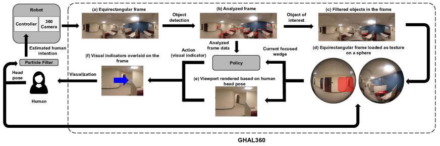
In this section, we present our framework called GHAL360, short for Guiding Human Attention with Learning in vision, that leverages the MTR’s 360 scene analysis capability to guide human attention to the remote areas with potentially rich visual information. Fig. 1 shows an overview of GHAL360.
III-A The GHAL360 Framework
Algorithm 1 delineates the procedure of GHAL360 and explains the different stages as well as the data flow at each stage. The input of GHAL360 includes , the name of a target object of interest as a string, and , a real-time object detection system.
After a few variable initializations (Lines 2-5), GHAL360 enters the main control loop in Line 7. The main control loop continues until the human finds the target object in the remote environment. Once a new frame () is obtained, GHAL360 analyzes the remote scene using an object detection system and stores the objects’ names and their locations in a dictionary (Line 10). The location of is then stored in and is used to draw the bounding box over .
If the target object is detected in the current frame (Line 16), Lines 17-25 are activated for guiding human attention. In Line 17 the current egocentric state representation () of the world is obtained using the function. Based on , the policy generated from the RL approach () returns an action, which is a guidance indicator to be overlayed on the current viewport (), and then is presented to the user via the interface. After executing every action , GHAL360 updates the Q-values for the state-action pair using the observed reward () and the next state () in Line 24. Finally, using the new Q-values, the policy () is updated, and in the next iteration, an optimal action is selected using the updated policy. The human head orientation () is sent to the particle filter as evidence to predict the human motion intention (). The controller then returns the control signal as based on to control the robot motion in the remote environment.
In the following subsections, we describe the key components of GHAL360.
III-B Scene Analysis
Once a new frame () is obtained, GHAL360 analyzes the remote scene information using an object detection system, where we use a state-of-the-art convolutional neural network (CNN)-based framework YOLOv3 [39]. All the objects (keys) in the frame along with their locations (values) are stored in a dictionary (Line 10). In our implementation, we divide the frame into eight equal wedges. These eight wedges together represent all the four cardinal and four intercardinal directions, i.e. [N, S, E, W, NE, NW, SE, SW]. Every wedge can have four different values based on the objects detected in that wedge:
-
•
: represents a wedge with no objects detected
-
•
: represents a wedge with clutter
-
•
: represents a wedge that contains only the object of interest
-
•
: represents a wedge containing clutter as well as the object of interest
where clutter indicates that the wedge contains one or more objects that are not the target object. The output of scene analysis is stored as a vector where each element represents the status of one of the wedge. The human operator can be focusing on one of these eight wedges. The function in Line 17 takes the output of the scene analysis along with the target object and current human head pose as input. The output of function is an egocentric state representation of the vector representing the locations of objects with respect to the wedge human is currently focusing on (). The generated egocentric version of the vector is then sent to the RL agent as the state representation of the current world, including both the output of scene analysis and the current status of the human operator.
III-C Equirectangular Frame Rendering
One of the ways to represent 360-degree videos is to project them onto a spherical surface. Consider the human head as a virtual camera inside the sphere. Such spherical projection helps to track the human head pose inside the frames. In our implementation, we construct a sphere and use as the texture information of the sphere. Inside the sphere, based on the yaw and pitch of the human head, the pixels in the human field of view are identified. Based on the human operator’s head pose obtained in Line 14, the viewport is rendered from the sphere. We use A-Frame, an open-source web framework for building virtual reality experiences 111https://aframe.io/, for rendering the equirectangular frames to create an immersive view of the remote environment.
III-D Policy for Guiding Human Attention
We use a reinforcement learning approach [16], Q-Learning, to let the agent learn a policy (for guiding human attention) by interacting with the environment. The mathematical representation of the state space is:
where represents the state of a particular wedge, as defined in Section III-B. In our case, , so , and . The state space () of the RL agent consists of a set of all possible state representations of the frames. All the state representations are egocentric, meaning that they represent the state of the world (locations of objects) with respect to the wedge human is currently focusing on. The domain consists of three different actions:
where and actions are the guidance indicators, while the action checks if the object of interest is present in the currently focused wedge or not. Based on , the policy generated from the RL approach () returns an action (), which can be a guidance indicator to enable the human to find the object of interest in the remote environment. Once the agent performs the action, it observes the immediate reward () and the next state (). Using the tuple (), the agent updates the Q-value for the state-action pair. Finally, the agent updates the policy at runtime based on its interaction with the environment. We use the BURLAP library 222http://burlap.cs.brown.edu/ for the implementation of our reinforcement learning agent and the domain.
III-E Particle Filter for Human Intent Estimation
We use a particle filter-based state estimator to identify the motion intention of the human operator. In GHAL360, the particle filter is first initialized with particles:
where each particle represents a state, which in our case is one of the eight wedges. Each particle has an associated weight () and is initialized as =. The belief state in particle filter is represented as:
where is the time step, is the evidence or the observation of the particle filter, and the belief state is updated based on the evidence obtained till time step . In our implementation, the evidence to the particle filter is the current change in human head orientation (left or right), and the current focused wedge. As the human starts to look around in the remote environment, based on the evidence the belief is updated:
After every observation, once the belief is updated, we calculate the density of particles for all the possible states, and the state with more than a threshold percentage of particles (70% in our case) is considered as the predicted human intention. Once the particle filter outputs the predicted human intention (Line 27), we use a controller that outputs a control signal to drive the robot base toward the intended area based on the predicted human intention. In case that the particle density does not reach the threshold in any wedge, the robot stays still until the particle filter can estimate the human motion intention.
III-F Telepresence Interface
Based on the action suggested by the policy, GHAL360 overlays visual indicators over the current viewport. This results in a new frame which is presented to the user via the interface (Fig. 2). The operator can use “click” and “drag” operations to look around in the remote environment. The telepresence interface provides a scroll bar to adjust the field of view of the human operator. Additionally, the users can easily change the web-based visualization to an immersive virtual reality experience via head-mounted displays (HMDs) via a VR button at the bottom right of the interface. In the VR mode, the users can use their head motions to adjust the view of the remote environment.
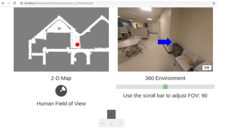
The telepresence interface also shows the 2D map of the remote environment. Based on the robot pose, a red circle is overlaid on the 2D map to indicate the live robot location in the remote environment. Additionally, we show a 2D icon to convey the head orientation of the human operator relative to the map. The 2D icon also shows the part of the frame which is in the field of view of the human operator (Fig. 2). The controller in Line 28 converts the estimated human intention into control command. The control commands are converted to a ROS “teleop” message and are passed on to the robot to remotely actuate it. Based on the control command, the robot is remotely actuated and the 2D map is updated accordingly to show the new robot pose.
IV Experiments
We conducted experiments to evaluate GHAL360 in a target-search scenario where a human was assigned the task of finding a target object in the remote environment using a MTR. We designed two types of simulation environments, 1. Abstract simulation, and 2. Realistic simulation. To facilitate learning, we designed Abstract simulation to enable the agent to learn a goal-oriented policy for guiding human attention. The learned system is then evaluated in Realistic simulation. The main difference between Abstract simulation and Realistic simulation is that the Abstract simulation eliminates the real-time visualization to speed up the learning process.


IV-A Abstract Simulation
We use the abstract simulator to let the agent learn a strategy to guide human attention toward an object of interest in a 360 frame. In our abstract simulation domain, we simulate the process of GHAL360 interacting with the “world” as a Markov decision process (MDP) [40]. The transition probability of the human following GHAL360’s guidance (left or right actions) is in abstract simulation. There is probability that the human randomly looks around in the remote environment. The transition probability of the action and the action is 0.8 while the transition probability for the action is 1.0.
The reward function is in the form of . After the agent takes action , if the value of (the wedge that the human is focusing on) is either or , as defined in Section III-B, the agent receives a big reward of . If the value of is either or after action , the agent receives a big penalty, in the form of a reward of . Each indication action ( or ) produces a small cost (negative reward) of if the value of is or . But if the or actions result in the value of becoming or , then the actions produces a slightly higher cost (negative) of .
After executing the action (), the agent moves to a next state () and receives a reward (). The reward is based on the value of which can be one of the four values as described in Section III-B, and is the wedge that the human operator is currently focusing on. If the agent takes action and transitions to , where value is or , the agent gets a reward as . But if the agent takes action , and the value of is either or , the agent gets a reward as . The actions and result in a reward of if , whereas the reward is if the value of or .
We trained the agent for episodes which resulted in the agent learning a policy for guiding human attention. We have evaluated the learned policy in the realistic simulation.
IV-B Realistic Simulation
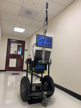
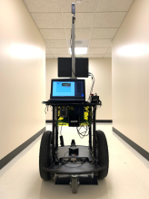
We used the equirectangular frames from the Matterport3D datasets (Fig. 3 - 3) as well as frames from the 360 videos captured from the real world (Fig. 3 - 3), and then simulated human and robot behaviors to build our realistic simulation. We used a Segway-based mobile robot platform to capture the videos (Fig. 4). The robot is equipped with an on-board 360 camera (Ricoh Theta V), and was teleoperated in a public space during the data collection process.
We model a virtual human in the realistic simulation that can also look around in the remote environment and send control signals to teleoperate the simulated robot using the interface. Moreover, as opposed to abstract simulation, the actions of the virtual human can be visualized in the interface, for example, if the virtual human looks to the left, the viewport is changed accordingly in the interface. The virtual human can both track the location of the simulated robot through the 2D map and perceive the 360 view of the remote environment via the telepresence interface. In our realistic simulation, the robot navigates in the 2D grid. If the virtual human tries to move to an inaccessible position, the robot stays still. Based on the control signal, the location of the robot is changed, and the interface is updated accordingly.
IV-C Baselines vs. GHAL360
We compared GHAL360 using a target-search scenario with different baselines from the literature. We also conducted ablation studies to investigate how individual components of GHAL360 contribute to the system. The different systems used for comparison are as follows:
-
•
MFO: Monocular Fixed Orientation based MTR, where the remote user needs to rotate the robot to look around in the remote environment [18].
-
•
ADV: All-Degree View systems which are typical MTRs equipped with a FOV camera. The human can use an interface to look around in the remote environment without having to move the robot base [19].
-
•
FGS: Fixed Guidance Strategy system which consists of a scene analysis component along with a hand-coded guidance strategy that greedily guides the human using the shortest path to the target object.
-
•
RLGS: Reinforcement Learning-based Guidance Strategy system uses the policy from RL to guide the human attention and suggests an optimal path for the human operator to locate the target object.
FGS and RLGS are ablations of approach, and the comparisons of FGS and RLGS with GHAL360 are ablation studies.
We used three different environments: two from the Matterport3D datasets, and one dataset collected from the real-world. In every environment, there were six sets of start positions for the robot in each of the environments, with each set includes positions of the same distance to the target. For each environment, we selected two target objects, and each of the target objects was specifically selected to ensure that they were unique in the environment to avoid the confusion resulting from finding a different instance of the same object at different locations. For example, the target objects selected in environment were “backpack” and “laptop”, while the target objects selected in environment were “bottle” and “television”. The initial orientation of the robot was randomly selected, and a set of one thousand paired trials were carried out for every two-meter distance from the target object until 12 meters. The virtual human carried out one random action every two seconds out of “move forward”, “move backward”, “look left”, and “look right” in the baselines (MFO and ADV). The actions “move forward”, “move backward” are also carried out randomly in FGS and RLGS, while the actions “look left” and “look right” are carried out randomly only until there are no visual indications. In case, there are visual indications, the human follows the indications with a probability. Using these actions, the simulated user could explore the remote environment. Once the target object is in the field of view of the human operator, the trial is terminated.
IV-D Illustrative Trial
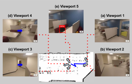
Consider an illustrative trial where the human-MTR team needed to locate a laptop in a remote environment. Fig. 5 shows the map of the remote environment with the robot’s trajectory marked in blue color. The arrows in Fig. 5 indicate the different human head orientations, and the red dotted lines point to the different viewports at these orientations. Fig. 5 (a) shows the initial viewport of a virtual human. The human started to look around at the remote environment to locate the laptop. Fig. 5 (b) shows the second viewport after the human looked left. Then the human again looked right, and the viewport can be seen in Fig. 5 (a). The human kept looking at the same position for next two time steps. The particle filter estimated the human’s intention, and accordingly, the controller output control signals to drive the robot to the next location.
The human continued to look around to find the laptop, and the particle filter constantly estimates the human motion intention resulting in the robot moving to different locations as shown by the blue marked trajectory in the map (Fig. 5). Finally, the robot reached location where the target object was located. As soon as the robot reached the location of the target object, the scene analysis component detected the laptop in the frame, and using the human head pose, GHAL360 overlayed the visual indicator over the viewport as seen in Fig. 5 (d). The indicator suggested the human to look right to find the laptop, but at first the human did not follow the guidance and looked left. Again, the visual indicator was overlayed on the new viewport to guide the human attention (Fig. 5 (c)). Now, at this time step, the human looked in the guided direction, and the viewport changed back to Fig. 5 (d). Finally, the human followed the visual indicator and looked further right, and Fig. 5 (e) shows the resulting viewport of the human with the laptop. Once the human found the target object, the trial was terminated.
IV-E Results
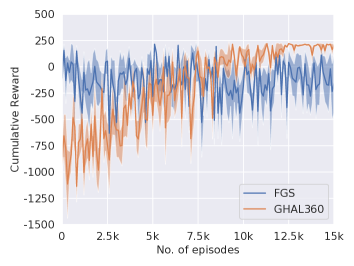
From the training episodes, we extracted different policies after each batch of episodes, and tested them in our realistic simulation. Fig. 6 shows the average cumulative reward and standard deviations over five runs. We plotted the mean cumulative reward (Fig. 6) of FGS and GHAL360 to compare the performance of hand-coded policy with the learned policy of GHAL360. The x-axis represents the episode number while the y-axis represents the cumulative reward. Fig. 6 shows that in the early episodes when the agent is still exploring, the cumulative reward for GHAl360 is much lower than FGS. But with the increasing number of episodes, it can be observed that GHAL360 outperforms FGS which represents the learned policy is superior to the hand-coded policy.
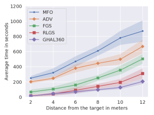
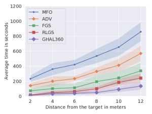
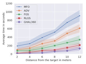
Fig. 7 shows the overall performance of GHAL360 compared to the other systems enlisted above. Each data point represents the average task completion time (y-axis) for six different distances (x-axis) (i.e., randomly sampled positions in each of the six distances). One thousand trials were divided over five runs to plot each data point. The shaded regions denote the standard deviations over five runs for each of the six distances.
From the results, it can be observed that GHAL360 outperforms all the baselines (MFO and ADV) in terms of average task completion time at all six distances in finding the target object. Moreover, compared to FGS, GHAL360 performs better in all three environments and at six different distances denoting that the human guidance using the learned strategy outperforms the hand-coded greedy.
Furthermore, in addition to the learned guidance strategy, GHAL360 utilizes a particle filter to estimate human intention and guide the robot base toward the intended direction. In the bottom left of Fig. 7(a) - 7(c), we can see that the average time of task completion is similar between RLGS and GHAL360. This indicates that particle filter in GHAL360 is less useful when the robot starts from a position that is close to the target object’s. When the robot is distant from the target object, we see the particle filter produces a significant improvement, as evidenced by seeing the far right of the Fig. 7(a) - 7(c). This observation confirms that the particle filter also contributes to the efficiency of GHAL360.
In addition to comparing the efficiency of different systems to GHAL360, we also compared the accuracy of target search tasks as shown in Table I. It can be observed that the accuracy of GHAL360 is higher in finding all the target objects, except for the “backpack” object in Environment 3. Also, we observed significant improvement in accuracy in Environment 2 for find the “television”. This shows that along with the improvements in efficiency, GHAL360 also provides higher accuracy in finding target objects as compared to the other systems.
| Env (target) | Accuracy | ||||
|---|---|---|---|---|---|
| MFO | ADV | FGS | RLGS | GHAL360 | |
| Env 1 (backpack) | .63 (.02) | .61 (.02) | .74 (.02) | .82 (.02) | .84 (.02) |
| Env 1 (laptop) | .65 (.01) | .66 (.02) | .75 (.02) | .82 (.02) | .85 (.01) |
| Env 2 (bottle) | .54 (.02) | .52 (.03) | .68 (.01) | .78 (.01) | .81 (.02) |
| Env 2 (television) | .58 (.01) | .59 (.01) | .71 (.01) | .80 (.03) | .87 (.03) |
| Env 3 (backpack) | .55 (.02) | .57 (.02) | .68 (.03) | .82 (.03) | .82 (.02) |
| Env 3 (laptop) | .56 (.02) | .56 (.01) | .69 (.02) | .80 (.01) | .83 (.02) |
| Overall | .58 (.04) | .58 (.05) | .71 (.03) | .81 (.02) | .84 (.02) |
V Conclusions and Future Work
In this paper, we develop a framework (GHAL360) that enables a mobile telepresence robot (MTR) to monitor the remote environment with all-degree scene analysis and actively guide the human attention to the key areas at the same time. We conducted experiments to evaluate GHAL360 in a target search scenario. From the results, we observed significant improvements in the efficiency of the human-MTR team in comparison to different baselines from the literature.
In the future, we would like to implement and evaluate GHAL360 on a real robot, and conduct studies with human participants for subjective analysis. Currently, the scene analysis component does not go beyond object detection in the current implementation of GHAL360. We would like to study if and how advanced scene analysis methods, such as those based on graph neural networks [41], can contribute to the system. Finally, our current controller suggests the robot to follow the human’s intention, which can possibly be improved using a planner to actively guide the human’s attention toward the direction of the target object, even when the object is not present in the immediate surroundings.
Acknowledgment
A portion of this research has taken place at the Autonomous Intelligent Robotics (AIR) Group, SUNY Binghamton. AIR research is supported in part by grants from the National Science Foundation (NRI-1925044), Ford Motor Company (URP Awards 2019-2021), OPPO (Faculty Research Award 2020), and SUNY Research Foundation. The work of Xiaoyang Zhang and Yao Liu is partially supported by NSF under grant CNS-1618931.
References
- [1] M. Minsky, “Telepresence,” OMNI Magazine, 1980.
- [2] A. Kristoffersson, S. Coradeschi, and A. Loutfi, “A review of mobile robotic telepresence,” Advances in Human-Computer Interaction, 2013.
- [3] M. Desai, K. M. Tsui, H. A. Yanco, and C. Uhlik, “Essential features of telepresence robots,” in 2011 IEEE Conference on Technologies for Practical Robot Applications, 2011, pp. 15–20.
- [4] L. Takayama and J. Go, “Mixing metaphors in mobile remote presence,” in Proceedings of the ACM 2012 conference on Computer Supported Cooperative Work, 2012, pp. 495–504.
- [5] C. Neustaedter, G. Venolia, J. Procyk, and D. Hawkins, “To beam or not to beam: A study of remote telepresence attendance at an academic conference,” in Proceedings of the 19th ACM conference on computer-supported cooperative work & social computing. ACM, 2016, pp. 418–431.
- [6] I. Rae and C. Neustaedter, “Robotic telepresence at scale,” in Proceedings of the 2017 CHI Conference on Human Factors in Computing Systems. ACM, 2017, pp. 313–324.
- [7] A. Cesta, S. Coradeschi, G. Cortellessa, J. Gonzalez, L. Tiberio, and S. Von Rump, “Enabling social interaction through embodiment in excite,” in ForItAAL: Second Italian Forum on Ambient Assisted Living, 2010, pp. 1–7.
- [8] A. M. Sabelli, T. Kanda, and N. Hagita, “A conversational robot in an elderly care center: an ethnographic study,” in 2011 6th ACM/IEEE International Conference on Human-Robot Interaction (HRI), 2011, pp. 37–44.
- [9] V. Ahumada-Newhart and J. S. Olson, “Going to school on a robot: Robot and user interface design features that matter,” ACM Transactions on Computer-Human Interaction (TOCHI), pp. 1–28, 2019.
- [10] I. Rae, G. Venolia, J. C. Tang, and D. Molnar, “A framework for understanding and designing telepresence,” in Proceedings of the 18th ACM conference on computer supported cooperative work & social computing. ACM, 2015, pp. 1552–1566.
- [11] J. Zhang, E. Langbehn, D. Krupke, N. Katzakis, and F. Steinicke, “A 360 video-based robot platform for telepresent redirected walking,” in Proceedings of the 1st International Workshop on Virtual, Augmented, and Mixed Reality for Human-Robot Interactions (VAM-HRI), 2018, pp. 58–62.
- [12] J. P. Hansen, A. Alapetite, M. Thomsen, Z. Wang, K. Minakata, and G. Zhang, “Head and gaze control of a telepresence robot with an hmd,” in Proceedings of the 2018 ACM Symposium on Eye Tracking Research & Applications, 2018, pp. 1–3.
- [13] T. C. Ruch and J. F. Fulton, “Medical physiology and biophysics,” Academic Medicine, vol. 35, no. 11, 1960.
- [14] M. Papinutto, J. Lao, M. Ramon, R. Caldara, and S. Miellet, “The facespan—the perceptual span for face recognition,” Journal of vision, vol. 17, no. 5, pp. 16–16, 2017.
- [15] V. R. Gaddam, M. Riegler, R. Eg, C. Griwodz, and P. Halvorsen, “Tiling in interactive panoramic video: Approaches and evaluation,” IEEE Transactions on Multimedia, vol. 18, no. 9, pp. 1819–1831, 2016.
- [16] R. S. Sutton and A. G. Barto, Reinforcement learning: An introduction. MIT press, 2018.
- [17] A. Chang, A. Dai, T. Funkhouser, M. Halber, M. Niessner, M. Savva, S. Song, A. Zeng, and Y. Zhang, “Matterport3d: Learning from rgb-d data in indoor environments,” International Conference on 3D Vision (3DV), 2017.
- [18] A. E. Kaplan, S. Keshav, N. L. Schryer, and J. Venutolo, “An internet accessible telepresence,” Multimedia systems, vol. 5, no. 2, pp. 140–144, 1997.
- [19] Y. Heshmat, B. Jones, X. Xiong, C. Neustaedter, A. Tang, B. E. Riecke, and L. Yang, “Geocaching with a beam: Shared outdoor activities through a telepresence robot with 360 degree viewing,” in Proceedings of the 2018 CHI Conference on Human Factors in Computing Systems. ACM, 2018.
- [20] R. Agarwal, A. W. Levinson, M. Allaf, D. V. Makarov, A. Nason, and L.-M. Su, “The roboconsultant: telementoring and remote presence in the operating room during minimally invasive urologic surgeries using a novel mobile robotic interface,” Urology, vol. 70, no. 5, pp. 970–974, 2007.
- [21] E. Paulos and J. Canny, “Social tele-embodiment: Understanding presence,” Autonomous Robots, vol. 11, no. 1, pp. 87–95, 2001.
- [22] M. Baker, R. Casey, B. Keyes, and H. A. Yanco, “Improved interfaces for human-robot interaction in urban search and rescue,” in IEEE International Conference on Systems, Man and Cybernetics, vol. 3, 2004, pp. 2960–2965.
- [23] H. Kuzuoka, S. Oyama, K. Yamazaki, K. Suzuki, and M. Mitsuishi, “Gestureman: a mobile robot that embodies a remote instructor’s actions,” in Proceedings of the ACM conference on Computer supported cooperative work, 2000, pp. 155–162.
- [24] M. T. Bolas and S. S. Fisher, “Head-coupled remote stereoscopic camera system for telepresence applications,” in Stereoscopic Displays and Applications, vol. 1256, 1990, pp. 113–123.
- [25] T. Aykut, C. Burgmair, M. Karimi, J. Xu, and E. Steinbach, “Delay compensation for actuated stereoscopic 360 degree telepresence systems with probabilistic head motion prediction,” in 2018 IEEE Winter Conference on Applications of Computer Vision (WACV), 2018, pp. 2010–2018.
- [26] S. Ikeda, T. Sato, and N. Yokoya, “High-resolution panoramic movie generation from video streams acquired by an omnidirectional multi-camera system,” in Proceedings of IEEE International Conference on Multisensor Fusion and Integration for Intelligent Systems, 2003, pp. 155–160.
- [27] M. Karimi, T. Aykut, and E. Steinbach, “Mavi: A research platform for telepresence and teleoperation,” arXiv preprint arXiv:1805.09447, 2018.
- [28] K. Yamaashi, J. R. Cooperstock, T. Narine, and W. Buxton, “Beating the limitations of camera-monitor mediated telepresence with extra eyes,” in Proceedings of the SIGCHI Conference on Human Factors in Computing Systems, 1996, p. 50–57.
- [29] G. M. Mair, “Telepresence-the technology and its economic and social implications,” in 1997 International Symposium on Technology and Society Technology and Society at a Time of Sweeping Change. Proceedings, 1997, pp. 118–124.
- [30] Y. Oh, R. Parasuraman, T. McGraw, and B.-C. Min, “360 vr based robot teleoperation interface for virtual tour,” in Proceedings of the 1st International Workshop on Virtual, Augmented, and Mixed Reality for HRI (VAM-HRI), 2018.
- [31] C. Zhou, S. Wang, M. Xiao, S. Wei, and Y. Liu, “Adap-360: User-adaptive area-of-focus projections for bandwidth-efficient 360-degree video streaming,” in Proceedings of the 28th ACM International Conference on Multimedia, 2020, pp. 3715–3723.
- [32] M. Hosseini and V. Swaminathan, “Adaptive 360 vr video streaming based on mpeg-dash srd,” in 2016 IEEE International Symposium on Multimedia (ISM). IEEE, 2016, pp. 407–408.
- [33] J. Aloimonos, I. Weiss, and A. Bandyopadhyay, “Active vision,” International journal of computer vision, vol. 1, no. 4, pp. 333–356, 1988.
- [34] A. Andreopoulos and J. K. Tsotsos, “50 years of object recognition: Directions forward,” Computer vision and image understanding, vol. 117, no. 8, pp. 827–891, 2013.
- [35] S. J. Dickinson, H. I. Christensen, J. K. Tsotsos, and G. Olofsson, “Active object recognition integrating attention and viewpoint control,” Computer vision and image understanding, vol. 67, no. 3, pp. 239–260, 1997.
- [36] D. Jayaraman and K. Grauman, “End-to-end policy learning for active visual categorization,” IEEE transactions on pattern analysis and machine intelligence, vol. 41, no. 7, pp. 1601–1614, 2018.
- [37] Y.-C. Su, D. Jayaraman, and K. Grauman, “Pano2vid: Automatic cinematography for watching 360 videos,” in Asian Conference on Computer Vision. Springer, 2016, pp. 154–171.
- [38] Y.-C. Su and K. Grauman, “Making 360 video watchable in 2d: Learning videography for click free viewing,” in 2017 IEEE Conference on Computer Vision and Pattern Recognition (CVPR), 2017, pp. 1368–1376.
- [39] J. Redmon and A. Farhadi, “Yolov3: An incremental improvement,” arXiv, 2018.
- [40] M. L. Puterman, Markov Decision Processes.: Discrete Stochastic Dynamic Programming. John Wiley & Sons, 2014.
- [41] F. Scarselli, M. Gori, A. C. Tsoi, M. Hagenbuchner, and G. Monfardini, “The graph neural network model,” IEEE transactions on neural networks, vol. 20, no. 1, pp. 61–80, 2008.