Spin Wave Based Approximate : Compressor
Abstract
In this paper, we propose an energy efficient SW based approximate : compressor comprising a -input and a -input Majority gate. We validate our proposal by means of micromagnetic simulations, and assess and compare its performance with one of the state-of-the-art SW, CMOS, and Spin-CMOS counterparts. The evaluation results indicate that the proposed compressor consumes % less energy in comparison with its accurate SW design version. Furthermore, it has the same energy consumption and error rate as the approximate compressor with Directional Coupler (DC), but it exhibits x lower delay. In addition, it consumes % less energy, while having % lower average error rate than the approximate CMOS counterpart. When compared with the other emerging technologies, the proposed compressor outperforms approximate Spin-CMOS based compressor by orders of magnitude in term of energy consumption while providing the same error rate. Finally, the proposed compressor requires the smallest chip real-estate measured in terms of devices
I Introduction
The information technology revolution has led to a rapid raw data rapid increase, which processing calls for high performance computing platforms Shah, Steyerberg, and Kent (2018). Up to date, downscaling Complementary Metal Oxide Semiconductor (CMOS) has been effective to satisfy these requirements, however, Moore’s law has reached its near economical end as CMOS feature size reduction is becoming increasingly difficult due to leakage, reliability, and cost walls Haron and Hamdioui (2008). As a result, different technologies have been investigated to replace CMOS such as graphene devices Jiang et al. (2019), memristor Nguyen et al. (2020), and spintronics Agarwal et al. (2018). In this paper, we chose to study one type of spintronics technology, the Spin Wave (SW) technology, which appears to open the way towards the most energy efficient digital computing paradigm Mahmoud et al. (2020a, 2021, b, c). SW based computing is promising for three main reasons Mahmoud et al. (2020a, 2021, b, c): 1) it has ultra-low energy consumption potential because it does not rely on electrons movements but just on their spinning around the magnetic field orientation Mahmoud et al. (2020a, 2021, b, c), 2) it is highly scalable because SW’s wavelength (which is the distance between two electrons that exhibit the same behavior) can reach the nanometer scale Mahmoud et al. (2020a, 2021, b, c), and 3) it has an acceptable delay Mahmoud et al. (2020a, 2021, b, c). As a consequence of these promising features, different researcher groups have made use of SW interaction to build logic gates and circuits.
The first experimental SW logic gate is an inverter, designed by utilizing a Mach-Zehnder interferometer Kostylev et al. (2005). Moreover, the Mach-Zehnder interferometer has been used to build a single output Majority, (N)AND, (N)OR, and X(N)OR gates Kostylev et al. (2005), while multi-output SW logic gates have been introduced in Mahmoud et al. (2020d, c, 2020). Furthermore, multi-frequency logic gates that enhance SW computing and storage capabilities have been proposed in Mahmoud et al. (2020b, 2021), and wavepipelining has been achieved with pulse mode operation in the SW domain by utilizing four cascaded Majority gates Mahmoud et al. (2021a). In addition, different SW circuits have been also demonstrated at conceptual level Khitun et al. (2011), simulation level Mahmoud et al. (2021b, 2021), and practical millimeter scale prototypes Gertz et al. (2015). All the aforementioned logic gates and circuits were designed to provide accurate results; however, many applications such as multimedia processing and social media are error-tolerant, and within certain error limits, they still function correctly Mittal (2016). Hence, those applications can benefit from approximate computing circuits, which save significant energy, delay, and area.
Based on the previous discussion on the SW technology potential and the approximate computing benefits one can conclude that SW approximate circuits are of great interest. In view of this observation, and given that multiplication is heavily utilized in error tolerant applications, and fast state-of-the-art multipliers are build with 4:2 compressors Kumar and Nath (2017) we introduce in this paper a novel approximate SW : compressor. The paper main contributions can be summarized as follows:
-
•
Developing and designing an approximate SW : compressor: We propose an approximate : compressor consisting of two Majority gates that provides an average error rate of %.
-
•
Enabling directional couplers free approximate circuit design: We demonstrate that Majority gates can be directly cascaded, i.e., without amplitude normalization of domain conversion, to form a : compressor with no additional average error rate penalty.
-
•
Validating the proposed : Compressor: We demonstrate by means of MuMax3 micromagnetics simulations the correct functionality of the proposed approximate : compressor.
-
•
Demonstrating the superiority: The proposed approximate SW : Compressor performance is assessed and compared with state-of-the-art SW, CMOS, and Spin-CMOS counterparts. The evaluation results indicate that the proposed compressor saves % energy in comparison with the accurate SW design, whereas it has the same energy consumption and error rate as the approximate compressor with Directional Coupler (DC), but while being 3x faster. In addition, the proposed compressor consumes % less energy while providing % less error rate when compared with the approximate CMOS counterpart. Moreover, the proposed compressor outperforms approximate Spin-CMOS equivalent design by orders of magnitude in terms of energy while having the same error rate. Finally, the proposed compressor requires the smallest chip real-estate.
The rest of the paper is organized as follows. Section II explains SW computing background. Section III introduces the proposed approximate : compressor and Section IV provides inside on the simulation setup and results. Section V reports performance evaluation and comparison with state-of-the-art data. Section VI concludes the paper.
II Spin Wave Based Technology Fundamental and Computing Paradigm
The magnetization dynamics caused by the magnetic torque when the magnetic material magnetization is out of equilibrium is captured by the Landau-Lifshitz-Gilbert (LLG) equation Mahmoud et al. (2020a):
| (1) |
where is the gyromagnetic ratio, the vacuum permeability, the magnetization, the saturation magnetization, the damping factor, and the effective field, which consists of the external field, the exchange field, the demagnetizing field, and the magneto-crystalline field.
Equation (1) has wave-like solutions under small magnetic disturbances, which are called Spin Waves (SWs) and are the collective excitations of the magnetization within the magnetic material Mahmoud et al. (2020a). A SW, as any other wave, is described by its amplitude , phase , wavelength , wavenumber , and frequency as graphically presented in Figure 1a) Mahmoud et al. (2020a). SW frequency and wavenumber are linked by the so called dispersion relation, which plays a fundamental role during the SW circuit design process Mahmoud et al. (2020a).
Generally speaking, information can be encoded in SW amplitude and phase at different frequencies Mahmoud et al. (2020a, b), while the interaction between SWs coexisting in the same waveguide is governed by the interference principle. Figure 1b) presents two SWs interaction situations: if they have the same phase, i.e., , they interfere constructively resulting in a larger amplitude SW, whereas if they have different phases, i.e., , they interfere destructively resulting in a diminished amplitude SW. Due to their very nature, SWs provide natural support for Majority function evaluation as the interference of an odd number of SWs emulates an Majority decision. For instance, if same amplitude, frequency, and wavelength SWs interfere, the result is a phase SW (logic ) if no more than one of them has a phase, and in a phase SW (logic ) otherwise, which is equivalent with the behavior of a 3-input Majority gate. Note that a CMOS 3-input majority gate implementation requires transistors, while in SW technology it only requires one waveguide. We note that if the SWs have different , , and , their interaction results in more sophisticated interferences, which might open different SW based computation paradigms. However, in this paper, we only consider the interaction of SWs with phase encoded information, i.e., logic and logic are represented by and phase, respectively.
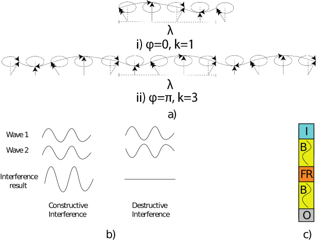
Figure 1c) presents a SW device, which consists of an excitation region , a waveguide , a functional region , and a detection region Mahmoud et al. (2020a); Chumak, Serga, and Hillebrands (2017). SW can be excited by means of, e.g., microstrip antennas, magnetoelectric cells, in region Mahmoud et al. (2020a); Chumak, Serga, and Hillebrands (2017). can be made out of different materials such as Permalloy, Yttrium iron garnet, CoFeB, which must be properly chosen as it has a direct impact on the SW properties, and propagation Mahmoud et al. (2020a); Chumak, Serga, and Hillebrands (2017). SWs can be amplified, normalized or interfere with other SWs within FR, and the output is detected at by using similar or different components than the one utilized in the excitation region Mahmoud et al. (2020a); Chumak, Serga, and Hillebrands (2017) by means of phase and threshold detection techniques Mahmoud et al. (2020a). Phase detection is based on comparing the resulted SW phase with a predefined phase. For instance, if the output SW has a phase difference , the output is logic , whereas the output is logic if the phase . Threshold detection relies on the comparison of the output SW amplitude with a predefined threshold value , i.e., if the SW amplitude is larger than , the output is logic , and , otherwiseMahmoud et al. (2020a); Chumak, Serga, and Hillebrands (2017).
III SW Approximate : Compressor
For many state-of-the-art applications, e.g., artificial neural network, machine vision, detecting events such as visual surveillance and people counting, which heavily rely on multiplications the availability of fast multipliers is essential. Wallace or Dadda tree multipliers are the fastest and can perform a multiplication within clock cycles. They embed stages, i.e., partial product generation, reduction tree, and carry propagation adder. In an n-bit multiplier the first stage requires gates to produce the partial products matrix, the second stage provides a logarithmic depth reduction of -bit numbers to two numbers without carry propagation, and the final stage is a carry propagate adder that sums-up the reduction tree outputs Parhami (2009). The to reduction has been traditionally done by means of Full and Half adders but : compressors based reduction trees can be shallower and have a more regular layout Parhami (2009). Thus, most of the state-of-the-art CMOS implementations make use of : compressors for which faster than cascaded FA implementations exists Momeni et al. (2015); Mori et al. (1991); Kumar and Nath (2017). Essentially speaking, a : compressor processes dots in the same column and generate one dot in the current column and a carry to the next column. To properly preserve the value carried by the inputs, after a FA delay, the 4:2 compressor generates a transport to the next column and receives a transport from the previous position, which it further process to generate the sum and a carry for the next column. Thus, the compressor has inputs (one of them coming from the previous column) and real outputs and one intermediate transport to the next column. Given that multiplication dominated error tolerant applications exist, e.g., multimedia processing and social media Mittal (2016), approximate CMOS : compressors have been proposed Kumar and Nath (2017), which enable significant energy consumptions and area saving.
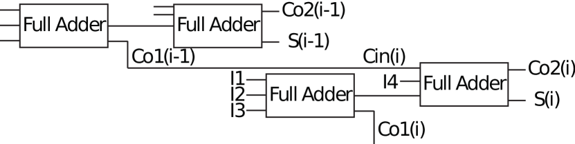
Figure 2 presents the conventional structure of an accurate SW : compressor, which consists of full adders. When applied in column of the partial product matrix it processes dots in that column and a Carry-in reported by a : compressor in column -, and generates outputs, intermediate transport that serves as for a counter in column +, the Sum and Carry-out . A straightforward SW : compressor implementation can be built using the SW full adder proposed in Mahmoud et al. (2021b), which provides accurate results with acceptable delay and energy efficiency as further discussed in Section V. However, as previously mentioned, many applications are error tolerant, and work properly within certain error limits Mittal (2016). Therefore, by enabling approximate computing, a more energy efficient SW : compressor can be made.
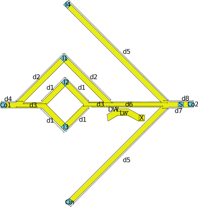
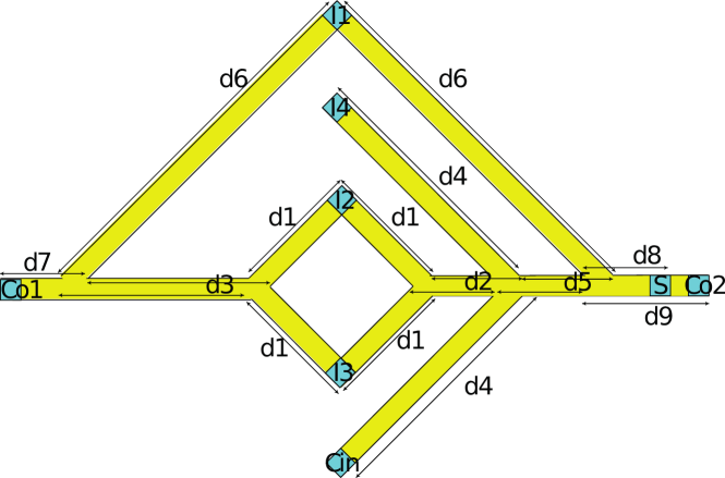
The straightforward implementation of a SW approximate : compressor can be done by means of the two approximate SW full adder proposed in Mahmoud et al. (2021c). This requires the cascading of two Full Adders (FAs), which cannot be performed straightforward because different FA input combinations generate different output SW strengths Mahmoud et al. (2021). To solve this issue, and make the compressor functions correctly a directional coupler is required Mahmoud et al. (2021) to normalize the output of the first FA before passing it to the second FA. Figure 3 presents the approximate compressor obtained by cascading two approximate FAs by means of a normalizer (directional coupler). However, the directional coupler induces substantial delay and area overheads, which makes working without it desirable. Therefore, we propose the novel directional coupler free approximate compressor depicted in Figure 4. The behaviour of the directly cascaded FAs is now obtained with a -input Majority gate and a -input Majority gate computing , and , respectively. The proposed : approximate compressor generates without any error, and and with an average error rate of %, and %, respectively. Table 1 presents the truth table of the accurate : compressor , , and , the approximate : compressor without directional coupler , , and , and the approximate : compressor with directional coupler , , and . As it can be observed from the Table, approximate : compressors with and without directional coupler provide the same average error rate of % because , and have an error rate of %, and %, respectively, whereas , and have an error rate of %, and %, respectively. Note that the erroneous outputs values in the Table are underlined and typeset in bold to highlight them.
| 1 | 1 | ||||||
| 1 | 1 | ||||||
| 1 | 1 | ||||||
| 1 | 1 | ||||||
| 1 | 1 | 0 | 0 | ||||
| 0 | 0 | 1 | 1 | ||||
| 1 | 1 | 0 | 0 | ||||
| 0 | 0 | 1 | 1 | ||||
| 0 | 0 | ||||||
| 0 | 0 | ||||||
| 0 | 0 | ||||||
| 0 | 0 |
To achieve proper functionality for the structure in Figure 4, the waveguide width must be smaller or equal to the SW wavelength to simplify the interference patterns, all SWs must be excited at the same amplitude, wavelength, and frequency, and the waveguide lengths must be accurately computed as they determine the SWs interaction modes. For example, if SW constructive (destructive) interference is envisaged for in phase (out of phase) SWs, the distances must be equal with , where ; this is the case for , , , and in Figure 4. In contrast, if SW constructive (destructive) interference is envisaged for out of phase (in phase) SWs, the distances must be equal with ; this is the case for and in Figure 4. On the output side, it is important to detect the output at specific position, i.e., if the desired output is the output itself, which is the case for in Figure 4, must be equal with , whereas if the inverted output is desired, the distance must be equal with . Moreover, the outputs must be detected as near as possible from the last interference point to capture large SW amplitude.
The proposed SW : compressor operation principle is as follows:
-
•
: SWs are excited at , , and with the same amplitude, wavelength, and frequency at the same time moment. The SW interfere constructively or destructively with SW depending on their phase difference, the resulted SW propagates through the waveguide, and subsequently interferes with the SW. The resulted SW is captured at the output based on phase detection.
-
•
and : SW interferes constructively or destructively with SW depending on their phase difference, and the resulted SW propagates through the waveguide to interfere with the SWs excited at and . The resulted SW propagates, and subsequently interferes with the SW. Finally, the resulted SW is captured at the outputs and based on the threshold detection.
IV Simulation Setup and Results
In order to validate the proposed structure by MuMax3 Vansteenkiste et al. (2014), we made use of the parameters specified in Table 3 Devolder et al. (2016). In addition, we assumed waveguide thickness and width of and , respectively, to guarantee high SW group velocity. Furthermore, we excite the SWs with Gaussian pulses with sigma modulated at to save energy, gaurantee the excitation of single frequency SWs, and achieve high group velocity. From the SW dispersion relation, at , we determine as being , which results in a = = . As discussed in Section III, the distances , , …, should be equal to integer multiples of , and are: = (n = 1), = (n = 3.5), = (n = 7), = (n = 2), = (n = 3.5), = (n = 7), = (n = 1), = (n = 0), and = (n = 1).
| Parameters | Values |
|---|---|
| Waveguide Material | |
| Saturation magnetization | A/m |
| Perpendicular anisotropy constant | MJ/ |
| Damping constant | |
| Exchange stiffness | pJ/m |
Figure 5 presents MuMax3 simulation results for {,,} = {,,}, {,,}, {,,}, {,,}, {,,}, {,,}, {,,}, {,,}, and {,,}. One can observe in the Figure that is detected correctly. for {,,}= {,,}, {,,}, {,,}, and {,,}, whereas for {,,} = {,,}, {,,}, {,,}, and {,,}, as it should, for a reading window starting after the input application.
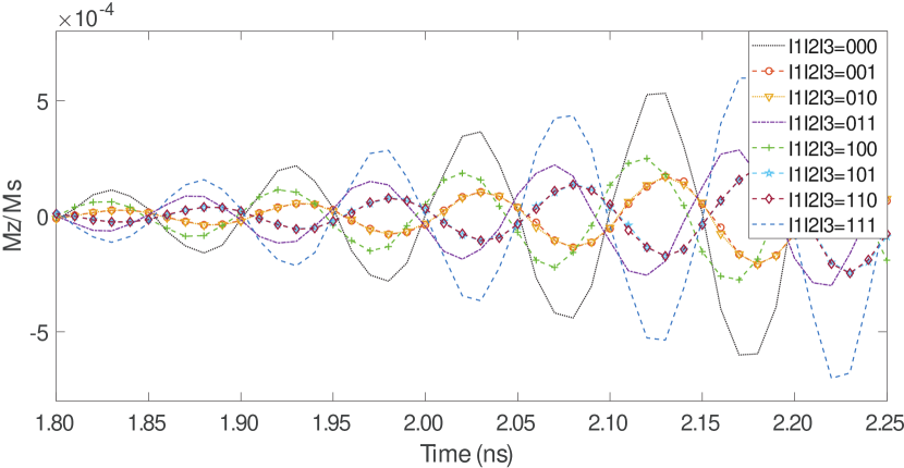
Table 3 presents the normalized magnetization of the : approximate compressor outputs and for all possible input combinations, i.e., {,,,,}= {,,,,}, {,,,,}, …, {,,,,}, and {,,,,}. Note that threshold technique is used to detect , and , i.e., if the normalized magnetization of the output SW is larger than the threshold, value , the output is logic and , otherwise. For detection is appropriate, which results in for input combinations {,,,,}= {,,,,}, {,,,,}, {,,,,}, {,,,,}, {,,,,}, {,,,,}, {,,,,}, {,,,,}, {,,,,}, {,,,,}, {,,,,}, {,,,,}, {,,,,}, {,,,,}, {,,,,}, and {,,,,}, and for the remaining cases, as it should.
The same threshold value is suitable for , but the threshold condition is flipped, i.e., if the resulted SW normalized magnetization is larger than , is logic , and logic , otherwise. This results in for {,,,,}= {,,,,}, {,,,,}, {,,,,}, {,,,,}, {,,,,}, {,,,,}, {,,,,}, {,,,,}, {,,,,}, {,,,,}, {,,,,}, {,,,,}, {,,,,}, {,,,,}, {,,,,}, and {,,,,}, and for the remaining cases, as it should.
Therefore, the MuMax3 simulations proves that the proposed : approximate compressor provides the expected functionality.
| Resulting SW | after thresholding | after thresholding | |
V Performance Evaluation and Discussion
We evaluate the proposed SW approximate : compressor and compare it in terms of error rate, energy consumption, delay, and area (the number of utilized devices) with the state-of-the-art SW, CMOS Manikantta Reddy et al. (2019), and Spin-CMOS Angizi et al. (2018) counterparts. In order to assess the performance of our proposal, we make the following assumptions: (i) Magnetoelectric (ME) cells having a power consumption of , and a delay of Zografos et al. (2015) are utilized for SW excitation/detection. (ii) SWs consume negligible energy during interference and propagation through waveguides. Note that these assumptions might need to be revisited to better capture SW technology future developments.
The proposed compressor with and without Directional Coupler (DC) delays can be calculated by adding the SW propagation determined by means of micro-magnetic simulations, and the delay of the excitation and detection cells, which sums-up to and , respectively. We note that in order to perform amplitude normalization the DC has to be rather long Mahmoud et al. (2021), which results in a large delay overhead.
Table 4 presents the evaluation results. When compared with the accurate SW compressor, which is a direct implementation consisting of two accurate SW adders in Mahmoud et al. (2021b), the proposed : compressor saves % energy and is x faster. Moreover, it has the same energy consumption, and error rate as the approximate compressor with DC, but it requires x less delay. In addition, it consumes % and % less energy, has approximately orders of magnitude higher delay, and exhibits % more and % less average error rate when compared with CMOS1 and CMOS2 designs in Table 4, respectively. When compared with same error rate Spin-CMOS (Spin-CMOS1 design in Table 4), it consumes orders of magnitude less energy and provides a % delay reduction. Although Spin-CMOS2 design provides % better average error rate, it is order of magnitude less effective in terms of energy consumption and slower. Note that the proposed compressor requires the smallest number of devices, which indicates that it potentially requires the lowest chip real-estate. .
| Technology | Type | Error Rate | Energy (fJ) | Delay (ns) | Device No. |
|---|---|---|---|---|---|
| Spin Wave | Accurate | ||||
| Spin Wave (with DC) | Approximate | ||||
| Spin Wave (without DC) | Approximate | ||||
| CMOS1 Manikantta Reddy et al. (2019) | Approximate | ||||
| CMOS2 Manikantta Reddy et al. (2019) | Approximate | ||||
| Spin-CMOS1 Angizi et al. (2018) | Approximate | ||||
| Spin-CMOS2 Angizi et al. (2018) | Approximate |
To get some inside on the implications of our proposal at the application level, we consider the well-known JPEG encoding, which makes use the Discrete Cosine Transform (DCT) , Wallace (1992) as discussion vehicle. Given that JPEG encoding is error tolerant and DCT is a multiplication dominated algorithm, 4:2 approximate compressors based tree multipliers are quite attractive for practical JPEG codec implementations. Such an approach has been presented in Angizi et al. (2018) and given that the approximate : compressor in Angizi et al. (2018) has the same average error rate as the one we propose, we can infer that replacing their compressor with ours does not change the image quality while resulting with orders of magnitude less energy consumption.
We note that the main goal of this paper is to propose and validate a SW : approximate compressor and as such we do not take into consideration thermal and variability effects. However, in Wang et al. (2018), it was suggested that thermal noise, edge roughness, and waveguide trapezoidal cross section do not have noticeable impact on gate functionality. Thus, we expect that the : approximate compressor functions correctly under their presence. However, further investigation of such phenomena is of great interest but cannot be performed before technology data and suitable simulation tools become available.
VI Conclusions
This paper proposed a Spin Wave (SW) based : approximate compressor, which consists of -input and -input Majority gates. We reported the design of approximate circuits without directional couplers, which are essential to normalize gate output(s) when cascading them in accurate circuit designs. We validated the proposed compressor by means of micromagnetic simulations, and compared it with the state-of-the-art SW, CMOS, CMOS, and Spin-CMOS counterparts.
The evaluation results indicated that the proposed : compressor saves % energy in comparison with the accurate SW compressor, has the same energy consumption, and error rate as the approximate compressor with DC, but it required x less delay. Moreover, it consumes % less energy, while having % lower error rate when compared with the approximate CMOS counterpart. Furthermore, it outperformes the approximate Spin-CMOS based compressor by orders of magnitude in term of energy consumption while providing the same error rate. Last but not least, the proposed compressor requires the smallest number of devices, thus it potentially requires the lowest chip real-estate.
Acknowledgement
This work has received funding from the European Union’s Horizon 2020 research and innovation program within the FET-OPEN project CHIRON under grant agreement No. 801055. It has also been partially supported by imec’s industrial affiliate program on beyond-CMOS logic. F.V. acknowledges financial support from Flanders Research Foundation (FWO) through grant No. 1S05719N.
References
- Shah, Steyerberg, and Kent (2018) N. D. Shah, E. W. Steyerberg, and D. M. Kent, JAMA 320, 27 (2018), https://jamanetwork.com/journals/jama/articlepdf/2683125/jama_shah_2018_vp_180051.pdf .
- Haron and Hamdioui (2008) N. Z. Haron and S. Hamdioui, in 2008 3rd International Design and Test Workshop (2008) pp. 98–103.
- Jiang et al. (2019) Y. Jiang, N. C. Laurenciu, H. Wang, and S. D. Cotofana, IEEE Transactions on Nanotechnology 18, 287 (2019).
- Nguyen et al. (2020) H. A. D. Nguyen, J. Yu, M. A. Lebdeh, M. Taouil, S. Hamdioui, and F. Catthoor, J. Emerg. Technol. Comput. Syst. 16 (2020), 10.1145/3365837.
- Agarwal et al. (2018) S. Agarwal et al., “International roadmap of devices and systems 2017 edition: Beyond cmos chapter.” Tech. Rep. (Sandia National Lab.(SNL-NM), United States, 2018).
- Mahmoud et al. (2020a) A. Mahmoud, F. Ciubotaru, F. Vanderveken, A. V. Chumak, S. Hamdioui, C. Adelmann, and S. Cotofana, Journal of Applied Physics 128, 161101 (2020a), https://doi.org/10.1063/5.0019328 .
- Mahmoud et al. (2021) A. Mahmoud, F. Vanderveken, C. Adelmann, F. Ciubotaru, S. Cotofana, and S. Hamdioui, IEEE Transactions on Circuits and Systems I: Regular Papers 68, 536 (2021).
- Mahmoud et al. (2020b) A. Mahmoud, F. Vanderveken, F. Ciubotaru, C. Adelmann, S. Cotofana, and S. Hamdioui, in 2020 Design, Automation Test in Europe Conference Exhibition (DATE) (2020) pp. 642–645.
- Mahmoud et al. (2020c) A. Mahmoud, F. Vanderveken, C. Adelmann, F. Ciubotaru, S. Cotofana, and S. Hamdioui, 2020 IEEE Computer Society Annual Symposium on VLSI (ISVLSI) , 60 (2020c).
- Kostylev et al. (2005) M. P. Kostylev et al., Appl. Phys. Lett. 87, 153501 (2005).
- Mahmoud et al. (2020d) A. Mahmoud, F. Vanderveken, C. Adelmann, F. Ciubotaru, S. Hamdioui, and S. Cotofana, AIP Advances 10, 035119 (2020d).
- Mahmoud et al. (2020) A. Mahmoud, F. Vanderveken, C. Adelmann, F. Ciubotaru, S. Hamdioui, and S. Cotofana, in 2020 IEEE 38th International Conference on Computer Design (ICCD) (2020) pp. 332–335.
- Mahmoud et al. (2021) A. N. Mahmoud, F. Vanderveken, C. Adelmann, F. Ciubotaru, S. Hamdioui, and S. Cotofana, IEEE Transactions on Magnetics , 1 (2021).
- Mahmoud et al. (2021a) A. Mahmoud, F. Vanderveken, C. Adelmann, F. Ciubotaru, S. Hamdioui, and S. Cotofana, in 2021 22nd International Symposium on Quality Electronic Design (ISQED) (2021) pp. 54–59.
- Khitun et al. (2011) A. Khitun et al., Journal of Applied Physics 110, 034306 (2011).
- Mahmoud et al. (2021b) A. Mahmoud, F. Vanderveken, F. Ciubotaru, C. Adelmann, S. Cotofana, and S. Hamdioui, in 2021 IEEE International Symposium on Circuits and Systems (ISCAS) (2021) pp. 1–5.
- Gertz et al. (2015) F. Gertz et al., IEEE Trans. Magn. 51, 1 (2015).
- Mittal (2016) S. Mittal, ACM Comput. Surv. 48 (2016), 10.1145/2893356.
- Kumar and Nath (2017) M. Kumar and J. Nath, IOP Conference Series: Materials Science and Engineering 225, 012136 (2017).
- Chumak, Serga, and Hillebrands (2017) A. V. Chumak, A. A. Serga, and B. Hillebrands, Journal of Physics D: Applied Physics 50, 244001 (2017).
- Parhami (2009) B. Parhami, Computer arithmetic: Algorithms and hardware designs, Computers & Mathematics with Applications (Oxford University Press; 2nd edition, 2009).
- Momeni et al. (2015) A. Momeni, J. Han, P. Montuschi, and F. Lombardi, IEEE Transactions on Computers 64, 984 (2015).
- Mori et al. (1991) J. Mori, M. Nagamatsu, M. Hirano, S. Tanaka, M. Noda, Y. Toyoshima, K. Hashimoto, H. Hayashida, and K. Maeguchi, IEEE Journal of Solid-State Circuits 26, 600 (1991).
- Mahmoud et al. (2021c) A. Mahmoud, F. Vanderveken, F. Ciubotaru, C. Adelmann, S. Hamdioui, and S. Cotofana, “Spin wave based approximate computing,” (2021c), arXiv:2103.12869 [cond-mat.mes-hall] .
- Vansteenkiste et al. (2014) A. Vansteenkiste et al., AIP Advances 4, 107133 (2014).
- Devolder et al. (2016) T. Devolder et al., Phys. Rev. B 93, 024420 (2016).
- Manikantta Reddy et al. (2019) K. Manikantta Reddy, M. Vasantha, Y. Nithin Kumar, and D. Dwivedi, AEU - International Journal of Electronics and Communications 107, 89 (2019).
- Angizi et al. (2018) S. Angizi, H. Jiang, R. F. DeMara, J. Han, and D. Fan, IEEE Transactions on Nanotechnology 17, 795 (2018).
- Zografos et al. (2015) O. Zografos, B. Sorée, A. Vaysset, S. Cosemans, L. Amarù, P.-E. Gaillardon, G. De Micheli, R. Lauwereins, S. Sayan, P. Raghavan, I. P. Radu, and A. Thean, in 2015 IEEE 15th International Conference on Nanotechnology (IEEE-NANO) (2015) pp. 686–689.
- Wallace (1992) G. K. Wallace, IEEE Transactions on Consumer Electronics 38, xviii (1992).
- Wang et al. (2018) Q. Wang, P. Pirro, R. Verba, A. Slavin, B. Hillebrands, and A. Chumak, Science Advances 4 (2018).