Direction-Assisted Beam Management in Full Duplex Millimeter Wave Massive MIMO Systems
Abstract
Recent applications of the Full Duplex (FD) technology focus on enabling simultaneous control communication and data transmission to reduce the control information exchange overhead, which impacts end-to-end latency and spectral efficiency. In this paper, we present a simultaneous direction estimation and data transmission scheme for millimeter Wave (mmWave) massive Multiple-Input Multiple-Output (MIMO) systems, enabled by a recent FD MIMO technology with reduced hardware complexity Self-Interference (SI) cancellation. We apply the proposed framework in the mmWave analog beam management problem, considering a base station equipped with a large transmit antenna array realizing downlink analog beamforming and few digitally controlled receive antenna elements used for uplink Direction-of-Arrival (DoA) estimation. A joint optimization framework for designing the DoA-assisted analog beamformer and the analog as well as digital SI cancellation is presented with the objective to maximize the achievable downlink rate. Our simulation results showcase that the proposed scheme outperforms its conventional half-duplex counterpart, yielding reduced DoA estimation error and superior downlink data rate.
Index Terms:
Full duplex, mmWave, massive MIMO, direction estimation, joint communication and sensing, optimization.I Introduction
In-band Full Duplex (FD) massive Multiple-Input Multiple-Output (MIMO) communication is a promising technology for the increasingly demanding data rate requirements of future wireless networks due to its inherent capability to enable simultaneous UpLink (UL) and DownLink (DL) communications within the entire frequency band [1, 2, 3]. In addition to concurrent UL/DL data transmission in reciprocal communications, the FD technology has been recently considered for simultaneous DL data transmission and UL Channel State Information (CSI) estimation, where FD Base Stations (BSs) transmit data symbols in the DL via CSI-dependent multi-user BeamForming (BF), while receiving UL training symbols from the user terminals [4, 5, 6]. The principal bottleneck of any FD system is the in-band Self-Interference (SI) signal at the Receiver (RX) side, resulting from the simultaneous transmission and reception. Recently in [7, 8, 9], FD MIMO systems operating at millimeter Wave (mmWave) frequencies were introduced, where SI suppression was achieved through a combination of propagation domain isolation, analog domain suppression, and digital SI cancellation techniques.
Wireless communications at mmWave frequencies are mainly realized via highly directional BF, which is enabled by massive MIMO transceivers [10] that are capable of analog or hybrid Analog and Digital (A/D) beamforming [11]. To alleviate the hardware cost in those transceiver architectures, the large-scale antenna arrays are connected to small numbers of Radio Frequency (RF) chains via analog preprocessing networks comprised of phase shifters [12]. However, the selection of the adequate analog beams from the predefined codebooks and the design of the digital beamformers require CSI knowledge, which is hard to acquire with realistically affordable latency, especially under mobility conditions (see, e.g.,[13] and references therein). This challenge will be naturally more pronounced in the envisioned FD massive MIMO systems operating at mmWave frequencies, where multiple UL and DL channels need to be estimated. In practice, the analog BF in mmWave massive MIMO systems is designed via beam switching between the communicating nodes in order to find a pair of beams from their available beam codebooks meeting a link performance indicator threshold [14, 15]. However, such time-consuming beam training procedures incur significant configuration overhead deprived of data transmission. Hence, beam misalignment may yield poor performance under mobility scenarios [16]. Alternatively, exploiting UL/DL reciprocity or position information, the DL BF can be performed in the direction of the UL dominant Direction-of-Arrival (DoA), thus, reducing the beam sweeping overhead [10, 17].
In this paper, we present a DoA-assisted beam management framework for FD mmWave massive MIMO systems, where the BS is equipped with a large antenna array realizing DL analog BF and few digitally controlled receive antenna elements used for UL DoA estimation. Capitalizing on the recently presented FD hardware architecture for hybrid A/D BF in [9], we propose a Simultaneous DoA estimation and Data Transmission (SDDT) scheme for boosting beam management in FD mmWave massive MIMO communications. Enabled by FD and leveraging channel reciprocity, we simultaneously estimate the UL dominant DoA and transmit analog beamformed data in the DL direction. We present a joint design of the DoA-assisted analog BF as well as the A/D SI cancellation units, targeting the maximization of the achievable DL rate. Our extensive simulation results considering a mmWave channel model showcase the FD-enabled gains of DoA-assisted beam management under various user mobility conditions. In particular, the proposed FD-based SDDT scheme achieves approximately the DL rate of conventional Half Duplex (HD) mmWave massive MIMO systems.
II System and Signal Models
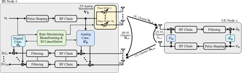
We consider an FD mmWave massive MIMO Base Station (BS) node equipped with TX and RX antenna elements communicating with a mobile single-antenna FD User Equipment (UE) node . In particular, in the TX of the BS node , a single RF chain is connected via phase shifters with a large antenna array of elements, whereas each of the few RX antennas is connected to a dedicated RF chain. In this work, a small number for is sufficient for UL DoA estimation; extension for large and analog combining is left for future work. Using the values of the phase shifters, we can formulate the TX analog beamforming vector , whose elements are assumed to have constant magnitude, i.e., . Besides, we assume that the angles of the analog phase shifters are quantized and have a finite set of possible values. Therefore, , where represents the predefined beam codebook including distinct vectors (or analog beams) [18, 13]. We assume that, for every channel use, the BS node transmits the complex-valued information data symbol (chosen from a discrete modulation set) after analog BF with . Similarly, the single-antenna FD UE node sends the training symbol through the UL channel. The signal transmissions at both node and node are power limited according to and , respectively.
II-A Channel Model
All the considered mmWave UL/DL channels consist of multiple propagation paths. In the spatial domain, each propagation path can be characterized by its Direction-of-Arrival (DoA)/ Direction-of-Departure (DoD) and the corresponding power as well as phase components [19]. For a certain coherence block, the UL channel including a Line-of-Sight (LoS) component and non-Line-of-Sight (nLoS) paths is mathematically expressed as
| (1) |
where and represent the complex gain and the DoA of the LoS path, respectively. Here, and are the complex gains and the DoAs of the nLoS path, respectively. Considering a Uniform Linear Array (ULA), the response vector for antenna elements and any DoA is formulated as [18]
| (2) |
where is the propagation signal wavelength and denotes the distance between adjacent antenna elements.
For the considered FD system, the UL and DL channels are reciprocal resulting in similar complex gains and DoAs/DoDs [18, 10]. Therefore, similar to (1), the DL channel can be expressed as follows:
| (3) |
In this paper, our goal is to estimate the LoS DoA using the UL training symbols and find the DoA-assisted analog beamformer that maximizes the DL rate. However, due to the FD operation at both nodes, the simultaneous DL data and UL training transmission induce SI signal in the RXs of the BS and UE. Following [9, 20], we consider the mmWave clustered model for the SI channels denoted by for the BS node and for the UE node , where represent the Rician factor.
II-B Received Signal Model
At the RX of the BS node , the training symbols transmitted from the UE node are received along with the SI signal induced by the simultaneous data and training signal transmissions. Due to limited propagation attenuation, the strong SI signal is capable of driving the RX RF chains into saturation. Therefore, as shown in Fig. 1, an -tap analog SI canceller is utilized to suppress the SI at the inputs of the RX RF chains, which is based on the TX RF chain output. Exploiting the low-complexity cancellation in [9], we employ the canceller taps at the TX RF chain output at the BS node resulting in an analog SI canceller where the number of taps does not scale with the number of antenna elements. To suppress the residual SI signal after analog cancellation, a digital SI canceller is utilized at the BS baseband. Denoting as the analog and digital SI cancellers, respectively, the baseband received signal at the BS node , , is given by
| (4) |
where is the zero-mean Additive White Gaussian Noise (AWGN) with variance . Similarly, the DL signal received at the UE node after analog and digital SI cancellation can be expressed as
| (5) |
where represents the AWGN with variance . As previously mentioned, for proper FD-based reception, the RXs’ RF chains need to be unsaturated from any residual SI stemming out analog SI cancellation at both nodes and [3, 21]. Denoting the residual SI power thresholds as and at node and node , respectively, the residual SI power constraints and are necessary to be satisfied for successful reception after analog SI suppression.
III DoA Estimation and DL Data Transmission
In this section, we introduce the proposed DoA-assisted analog beam management protocol along with the DoA tracking scheme for the considered UL/DL mmWave channel with the proposed FD massive MIMO system.
III-A UL/DL Channel Evolution Properties
We assume wireless communications in Time Division Duplexing (TDD) manner, where the considered channels remain constant for all the channel uses in a time slot, and the channel properties (i.e., DoAs/DoDs, complex path gains) of the successive time slots are temporally correlated. Each time slot of time units contains symbols (i.e., channel uses). For any consecutive and time slots, the evolution of LoS DoA component is expressed similar to [22] as
| (6) |
where depends on the velocity of the UE node and the time slot duration . We also assume that the UE node is moving with the constant velocity , hence, with being the distance between the UE and the BS nodes. The evolution model for the LoS complex path gain is given by the first-order Gauss-Markov model as [22]
| (7) |
where is the correlation coefficient, and is the zero-mean complex Gaussian noise distributed as . The DoAs and complex path gains of the nLoS components are assumed to change randomly between consecutive time slots. In this paper, we propose to track only the LoS DoA component for each time slot, and then use it analog beam selection. The estimation of all complex path gains and their correlation coefficients is left for future investigation.
III-B Proposed FD-Based SDDT Protocol
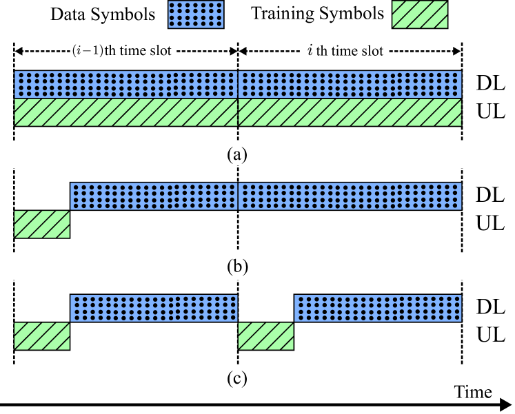
The proposed protocol for simultaneous DoA estimation and data transmission is illustrated in Fig. 2(a), where the DL channel is dedicated for data transmission, while the UL is accessed to transmit training symbols. The procedures of DoA-based tracking and transmission are described as follows:
-
1.
DL Data transmission at any th time slot leverages the DOA estimation for the previous th time slot, which is realized via simultaneous UL transmission of orthogonal training symbols sent from the UE node .
-
2.
Capitalizing on the UL/DL reciprocity, any LoS component estimation is used during the next th time slot for the DL data transmission precoding.
-
3.
The DL analog beamformer at each th time slot is chosen according to subject to the satisfaction of the residual SI power constraints.
In Fig. 2(b), a conventional HD DoA-assisted analog beamforming scheme is illustrated, where, contrary to the FD case, a fraction of the available symbols in a time slot is dedicated for DoA estimation. Once the DoA of a time slot is estimated, its analog beamforming and that of the succeeding ones utilizes the same DoA estimation, unless the received Signal-to-Noise Ratio (SNR) falls below a certain threshold; in this case, a DoA estimation update occurs. An HD data transmission protocol with DoA estimation at each time slot is shown in Fig. 2(c).
III-C UL DoA Estimation
As previously discussed, the UL training symbols at any th time slot are used for this slot’s LoS DoA estimation, which is leveraged for analog BF at the th time slot. For this estimation, we deploy the MUltiple SIgnal Classification (MUSIC) algorithm; other DoA estimation techniques can be used as well [23]. Starting from (4), the received training symbols at any th time slot can be grouped in . For the MUSIC DoA estimation, the received signal covariance matrix can be estimated as
| (8) |
By taking the eigenvalue decomposition of the estimated sample covariance matrix , it is deduced that:
| (9) |
where are the eigenvalues of and contains their corresponding eigenvectors. Since we are interested in estimating the DoA of the LoS component, the matrix can be partitioned as , where the columns in are the eigenvectors spanning the noise subspace and is the signal space eigenvector. We next project the search vector onto the noise subspace and calculate the spectral peak as
| (10) |
Finally, the position of the spectral peak is the estimated LoS DoA corresponding to this th time slot.
III-D DoA-Assisted Analog Beamforming and DL Rate
Capitalizing on the UL/DL reciprocity and the estimated LoS DoA component, we propose to approximate the DL channel at each th time slot as follows:
| (11) |
This approximation is further used during this th time slot to find the best analog beamformer at the BS node , via searching in the available beam codebook . Therefore, the instantaneous achievable DL rate per channel use for the proposed FD-based SDDT scheme at this time slot is given by
| (12) |
where is the residual signal power after both A/D SI cancellation at the UE node .
IV Proposed SDDT Optimization Framework
In this section, we focus on the joint design of the analog beamformer , the analog SI cancellers and , as well as the digital canceller and at the BS node and the UE node , which maximize the estimated achievable DL rate in (12) at each th time slot. Based on the availability of the DL channel estimation , as well as the SI estimations and , we consider the optimization problem:
| s.t. | ||||
| (13) |
The first and second constraints impose the RX RF chain saturation thresholds and after analog cancellation at nodes and , respectively. These saturation thresholds ensure successful reception of the training symbols and decoding of BS’s data symbols. The next two constraints in (IV) refer to the nodes’ average transmit powers. The final constraint enforces the predefined analog codebook for the BS beamformer.
The optimization problem in (IV) is a non-convex problem with coupling variables, hence, quite difficult to tackle. In this work, we solve it suboptimally using alternating optimization, leaving other possibilities for future work. First, we find the BS analog beamformer via the following problem:
| (14) |
The exhaustive search for this problem can be easily implemented by a simple look-up table given the estimated SI channel and the estimated DL channel . Following the analog SI canceller structure in [9] and using , we next seek the -tap analog canceller with that satisfies the first threshold constraint. The single-tap canceller at node is obtained as . To maximize the signal-to-interference-plus-noise ratio, the digital cancellers and are set as the respective complementary residual SI channels after analog SI cancellation. Our solution for the optimization problem (IV) is summarized in Algorithm 1.
V Numerical Results
In this section, we present simulation results for the performance of the proposed SDDT scheme for FD mmWave massive systems in comparison with HD counterparts.
V-A Simulation Parameters
We perform an extensive waveform simulation following the FD massive MIMO architecture illustrated in Fig. 1 when operating at mmWave frequencies, where a FD massive MIMO node is communicating with a single-antenna FD UE node . We have assumed that the single TX RF chain at the BS node is connected to a ULA consisting of antenna elements. In contrast, on the RX side, RX antennas are connected to their dedicated RX RF chains. The UE node employs a non-ideal single-tap SI canceller, where the FD massive MIMO BS node deploys an taps analog SI canceller [9]. The multi-path UL and DL channels are simulated as mmWave channels at GHz each with one LoS and nLoS channel paths. Considering the distance of the BS node from the UE, the pathloss of the both UL and DL channels is assumed to be dB with a dB Rician factor between the LoS and nLoS paths [19]. In addition, the SI channels are modeled as Rician fading channels with a -factor of dB and pathloss dB [3]. The RX noise floors at all nodes were assumed to be dBm. To this end, the RXs have an effective dynamic range of dB provided by -bit Analog-to-Digital Converters (ADC) for a Peak-to-Average-Power-Ratio (PAPR) of dB. Therefore, the residual SI power after analog SI cancellation at the input of each RX RF chain has to be below dBm to avoid signal saturation. For the considered FD massive MIMO architecture, we have assumed that the UE is moving at a constant velocity of km/h for a duration of time slots, where each time slot is considered to be msec with symbols. For the BS analog beamformer, we have used a -bit beam codebook based on the Discrete Fourier Transform (DFT) matrix. We have used independent Monte Carlo simulation runs to calculate the performance of all considered DoA estimation and data transmission designs.
V-B Compared HD Massive MIMO Designs
We compare the performance of the proposed FD-based SDDT scheme with three HD DoA-assisted DL analog beam management techniques. First, we consider the “HD with Initial DoA” case, where DoA is estimated using the UL training symbols only in the first time slot, and for the rest of the time slots, the same DoA is utilized for finding the DL analog beam. Secondly, we simulate the “HD DoA in Each Slot” scheme, where, for every time slot, a fraction of the UL training symbols is utilized for DoA estimation, and the rest of the symbols are dedicated for data transmission with analog BF. Finally, we consider the “HD DoA with Update” technique, where DL analog BF in each time slot is performed using the DoA estimation of the previous time slot, unless more than dB SNR loss occurs in the received DL signal, which triggers the initialization of a DoA-based analog beamformer update. In addition to the latter HD cases, we have simulated the achievable DL rate for the proposed FD-based SDDT scheme with ideal DoA estimation.
V-C DoA Estimation Error and Average DL Rate
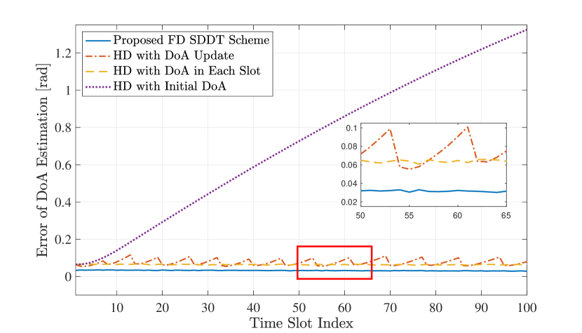
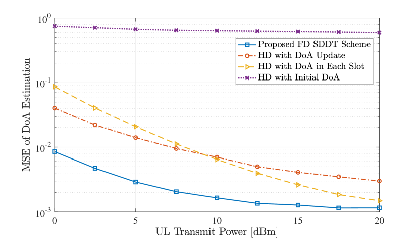
In Fig. 3, the LoS DoA estimation error in radians is illustrated with respect to the time slot index. We have considered that the FD massive MIMO node communicates with the mobile single-antenna FD UE , while the latter sends training symbols in the UL for DoA estimation with power dBm. It is shown in the figure that the “HD with Initial DoA” scheme provides higher DoA estimation error with increasing time slot index. This happens because it only estimates the DoA in the first time slot. As the UE moves, the initial DoA becomes outdated, and hence, a DoA estimation as well as an analog beam update are required. As illustrated in the inset plot, the “HD DoA with Update” scheme performs an LoS DoA update after reaching approximately rad estimation error, while the “HD DoA in Each Slot” results in a steady error as the estimation is performed in each time slot. It is, however, evident from Fig. 3 that the proposed FD-based SDDT scheme with a -tap analog canceller provides substantially lower DoA estimation error compared to the HD cases across all time slots for the considered dBm UL transmit power. In Fig. 4, we plot the Mean Squared Error (MSE) of the DoA estimation for all considered schemes as a function of the UL transmit power in the range dBm. It is clear from the figure that the MSE of the DoA estimation reduces with increasing UL transmit power. This happens because the received SNR at the BS increases. It is also shown that the proposed scheme outperforms all considered HD-based counterparts.
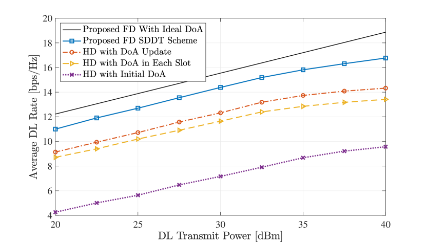
Figure 5 illustrates the achievable DL rate of the proposed SDDT scheme as a function of the DL transmit power, considering that the BS node is transmitting data in the DL via analog BF to the constant-velocity mobile UE node , while receiving UL training symbols with dBm transmit power. It is demonstrated that the “HD with Initial DoA” provides the lowest DL rate for all DL transmit power levels, as it suffers from the highest DoA estimation error. It is also shown that, although the “HD DoA with Update” scheme achieves higher DoA estimation error compared to the “HD DoA in Each Slot” approach, as depicted in Fig. 3, it achieves higher DL rate across all DL transmit powers. This is due to the fact that the later HD DoA-assisted beam management scheme utilizes symbols in each time slot for DoA estimation, whereas the “HD DoA with Update” approach is capable of sending data symbols for the whole time slot when it doesn’t have to update the DoA estimation. It is finally evident that the proposed scheme with -tap analog cancellation achieves a higher DL rate compared to all the HD-based schemes fo all DL transmit powers. In particular, for the large DL transmit power of dB, the proposed scheme for FD mmWave massive MIMO systems results in of the achievable DL rate with the best HD-based counterpart.
VI Conclusion
In this paper, we presented a novel DoA-assisted analog beam management scheme for FD mmWave massive MIMO systems. We considered an FD massive MIMO BS with an analog beamformer serving a mobile single-antenna FD user moving at a constant velocity. By adopting the MUSIC DoA estimation technique as an example, we presented a joint design of the DoA-assisted analog beamformer and A/D SI cancellation at the BS node maximizing the DL rate. Our performance evaluation results considering a realistic mmWave channel model demonstrated the superior achievable rates of the proposed FD-based SDDT scheme. In future work, the simultaneous DoA estimation and data transmission protocol will be considered for multi-user FD massive MIMO systems with both A/D precoders and combiners at all involved nodes.
Acknowledgments
This work was partially funded by the National Science Foundation CAREER award #1620902.
References
- [1] “The next hyper-Connected experience for all,” White Paper, Samsung 6G Vision, Jun. 2020.
- [2] H. Alves, T. Riihonen, and H. A. Suraweera, Full-Duplex Communications for Future Wireless Networks. Singapore: Springer, 2020.
- [3] G. C. Alexandropoulos and M. Duarte, “Joint design of multi-tap analog cancellation and digital beamforming for reduced complexity full duplex MIMO systems,” in Proc. IEEE ICC, Paris, France, May 2017.
- [4] M. A. Islam, G. C. Alexandropoulos, and B. Smida, “Simultaneous downlink data transmission and uplink channel estimation with reduced complexity full duplex MIMO radios,” in Proc. IEEE ICC, Dublin, Ireland, Jun. 2020.
- [5] J. Mirza, G. Zheng, K.-K. Wong, S. Lambotharan, and L. Hanzo, “On the performance of multiuser MIMO systems relying on full-duplex CSI acquisition,” IEEE Trans. Wireless Commun., vol. 66, no. 10, pp. 4563–4577, Oct. 2018.
- [6] M. A. Islam, G. C. Alexandropoulos, and B. Smida, “Simultaneous data communication and channel estimation in multi-user full duplex MIMO systems,” in Proc. IEEE ASILOMAR, Pacific Grove, USA, Nov. 2020.
- [7] Z. Xiao, P. Xia, and X.-G. Xia, “Full-duplex millimeter-wave communication,” IEEE Wireless Commun., vol. 24, no. 6, pp. 136–143, Dec. 2017.
- [8] I. P. Roberts, H. B. Jain, and S. Vishwanath, “Equipping millimeter-wave full-duplex with analog self-interference cancellation,” in Proc. IEEE ICC, Dublin, Ireland, Jun. 2020.
- [9] G. C. Alexandropoulos, M. A. Islam, and B. Smida, “Full duplex hybrid A/D beamforming with reduced complexity multi-tap analog cancellation,” in Proc. IEEE SPAWC, Atlanta, USA, May 2020.
- [10] E. Björnson, E. G. Larsson, and T. L. Marzetta, “Massive MIMO: Ten myths and one critical question,” IEEE Commun. Mag., vol. 54, no. 2, pp. 114–123, Feb. 2016.
- [11] E. Vlachos, G. C. Alexandropoulos, and J. Thompson, “Wideband MIMO channel estimation for hybrid beamforming millimeter wave systems via random spatial sampling,” IEEE J. Sel. Topics Signal Process., vol. 13, no. 5, pp. 1136–1150, Sep. 2019.
- [12] V. Venkateswaran and A.-J. van der Veen, “Analog beamforming in MIMO communications with phase shift networks and online channel estimation,” IEEE Trans. Signal Process., vol. 58, no. 8, pp. 4131–4143, Aug. 2010.
- [13] G. C. Alexandropoulos, I. Vinieratou, M. Rebato, L. Rose, and M. Zorzi, “Uplink beam management for millimeter wave cellular MIMO systems with hybrid beamforming,” in Proc. IEEE WCNC, Nanjing, China, Apr. 2021.
- [14] M. Giordani, M. Polese, A. Roy, D. Castor, and M. Zorzi, “A tutorial on beam management for 3GPP NR at mmWave frequencies,” IEEE Commun. Surveys Tuts., vol. 21, no. 1, pp. 173–196, 2019.
- [15] I. Aykin and M. Krunz, “Efficient beam sweeping algorithms and initial access protocols for millimeter-wave networks,” IEEE Trans. Wireless Commun., vol. 19, no. 4, pp. 2504–2514, Apr. 2020.
- [16] J. Palacios, D. De Donno, and J. Widmer, “Tracking mm-Wave channel dynamics: Fast beam training strategies under mobility,” in Proc. IEEE INFOCOM, Atlanta, USA, May 2017, pp. 1–9.
- [17] G. C. Alexandropoulos, “Position aided beam alignment for millimeter wave backhaul systems with large phased arrays,” in Proc. IEEE CAMSAP, Curacao, Dutch Antilles, Dec. 2017, pp. 1–5.
- [18] J. P. González-Coma et al., “Channel estimation and hybrid precoding for frequency selective multiuser mmWave MIMO systems,” IEEE J. Sel. Topics Signal Proces., vol. 12, no. 2, pp. 353–367, Mar. 2018.
- [19] M. R. Akdeniz et al., “Millimeter wave channel modeling and cellular capacity evaluation,” IEEE J. Sel. Areas Commun., vol. 32, no. 6, pp. 1164–1179, Jun. 2014.
- [20] K. Satyanarayana et al., “Hybrid beamforming design for full-duplex millimeter wave communication,” IEEE Trans. Veh. Technol., vol. 68, no. 2, pp. 1394–1404, Dec. 2018.
- [21] M. A. Islam, G. C. Alexandropoulos, and B. Smida, “A unified beamforming and A/D self-interference cancellation design for full duplex MIMO radios,” in Proc. IEEE PIMRC, Istanbul, Turkey, Sep. 2019.
- [22] V. Va, H. Vikalo, and R. W. Heath, “Beam tracking for mobile millimeter wave communication systems,” in Proc. IEEE GlobalSIP, Dec. 2016, pp. 743–747.
- [23] H. Krim and M. Viberg, “Two decades of array signal processing research: the parametric approach,” IEEE Signal Process. Mag., vol. 13, no. 4, pp. 67–94, Jul. 1996.