Implementation of a 46-node quantum metropolitan area network
Abstract
Quantum key distribution (QKD) enables secure key exchanges between two remote users. The ultimate goal of secure communication is to establish a global quantum network. The existing field tests suggest that quantum networks are feasible. To achieve a practical quantum network, we need to overcome several challenges, including realising versatile topologies for large scales, simple network maintenance, extendable configuration, and robustness to node failures. To this end, we present a field operation of a quantum metropolitan-area network with 46 nodes and show that all these challenges can be overcome with cutting-edge quantum technologies. In particular, we realise different topological structures and continuously run the network for 31 months, by employing standard equipment for network maintenance with an extendable configuration. We realise QKD pairing and key management with a sophisticated key control center. In this implementation, the final keys have been used for secure communication such as real-time voice telephone, text messaging, and file transmission with one-time pad encryption, which can support 11 pairs of users to make audio calls simultaneously. Combined with inter-city quantum backbone and ground-satellite links, our metropolitan implementation paves the way toward a global quantum network.
Introduction
The ultimate goal of quantum key distribution (QKD) [1, 2] is to construct a global quantum network, wherein all communication traffics have information-theoretical security guarantees. A global QKD network consists of two main types of links: the ground network (mainly fibre based) and the satellite network (mainly free-space based). The ground network can be further divided into backbone, metropolitan, and access networks, which cover inter-city distances, metropolitan distances, and fibre-to-the-home distances, respectively. The feasibility of QKD between two users has been extensively studied, for example, through long-distance free space [3], telecom fibres [4], and simulated ground-satellite links [5, 6]. Field tests of QKD networks have been realised, including the three-user network by DARPA (2003) [7], the six-node SECOQC network in Europe (2008) [8], SwissQuantum network (2009) [9], the USTC network [10], the six-node mesh-type network in Tokyo (2011) [11], and the small-scale metropolitan all-pass and inter-city quantum network [12, 13]. The satellite network is a promising way to realise intercontinental secure communication due to the low transmission attenuation in space. The satellite can serve as a trusted relay, connecting remote user nodes or sub-networks [14]. Recently, a large-scale satellite network has been implemented [15], consisting of four metropolitan-area networks, a backbone network and two satellite–ground links. Here, we summarize the existing network implementations in Table 1. For a full review of the subject, one can refer to the recent review article [16] and references therein.
| Network | # of Nodes | Running time | Topology | Key rate |
|---|---|---|---|---|
| (order of magnitude) | (at max distance/loss) | |||
| DARPA [7] | unknown | tree | kbps ( km) | |
| SECOQC [8] | hour | mesh | kbps ( km) | |
| SwissQuantum [9] | year | fully-connected | kbps ( km) | |
| Tokyo [11] | year | mesh | kbps ( km) | |
| USTC [10] | unknown | star | kbps ( dB) | |
| USTC [12] | week | fully-connected | kbps ( km) | |
| USTC [13] | week | star | kbps ( km) | |
| USTC [15] | year | mesh | 1.1kbps ( km) | |
| Hefei (This work) | year | fully-connected & star | kbps ( km) |
Nevertheless, these QKD experiments and networks are still preliminary demonstrations with limited scales with less than ten nodes, making it insufficient for meeting the demands of actual metropolitan communication. Furthermore, realising a practical QKD network is not simply extending the number of nodes; while many scientific and practical issues, such as (a) network topology, (b) network scalability, (c) key management, (d) practical applications, and (e) network robustness, need to be considered. Thus far, realising a practical large QKD network still remains as a major challenge in quantum communication.
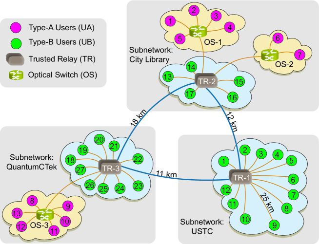
In this work, we construct a 46-node quantum metropolitan area network throughout the city of Hefei, which connects 40 user nodes, three trusted relays, and three optical switches, as shown in Fig. 1. The network covers the entire urban area and connects several major organizations in the city districts, including governments, banks, hospitals, universities, and research institutes. In our network, we (a) implement versatile connection topologies for different hierarchies of users, (b) use standard equipments with a scalable configuration, (c) integrate systematic key management, (d) realise various robust application modules, and (e) deal with node failures. As a result, we address the major challenges in realising a large scale practical QKD network.
Results
Network topology
We first review the basic topological structures in a network. There are three general ways of connecting and distributing keys between users in a quantum network. The most robust method uses a fully connected topology. Here, each user is directly connected to every other user in the network. This type of network contains no relays; hence it is robust against a single point of failure, and the users do not need to trust one another. That is to say that a system failure or dishonest user would not affect the communication between other users. The main drawback of this type of network is that the number of links (and cost) of a fully connected network quadratically increases with the number of users. Thus, such a network is typically used for connections between a small number of major nodes.
Alternatively, the user nodes can also be connected via a central switch (relay). In this star-like network, the number of links linearly increases with the number of users. In addition, the users do not need to trust each other or the relay. Because the switch only transfers quantum signals, users can execute QKD protocols as if they are directly connected. The drawback of this type of network is that it is not robust against a single point of failure. That is to say that if the switch relay fails, the entire network will be brought down. The transmission distance of quantum signals is twice the length of the link between the users and the switch; hence this kind of network is typically used for local connections.
In the star-like topology, we can replace the switch with a trusted node. In this trusted node network, every user runs QKD protocols with a central relay, and two users can combine their keys between the central relay to form their own keys. In QKD, the secure key transmission distance is limited; thus, the size of a directly communicated quantum network is also limited. However, the size of the network can be extended by the introduction of trusted relays. Two distant users could also build secure keys with the help of a sufficient number of trusted relays. In practice, the Shanghai–Beijing backbone employs this technique to scale the QKD distance. The disadvantage of this type of network is that the users need to trust the relay. To construct a global quantum network, it is important to realize different topological structures in practice.
Our network consists of three sub-networks located at, USTC, QuantumCTek, and the City Library, and are distributed approximately 15 kms apart. The longest fibres connecting the east and west end-users is approximately 45 km, and that connecting the south and north end-users is approximately 42 km. The longest direct distance between two users in the network is approximately km. We realise two basic types of topological connection structures, including the full connection between the three subnetworks and the star-like connection for local access networks. The fully connected topology is applied to guarantee the robustness between the most important users; while the star-like connection is used for a more efficient network connection. At the center of the star-like subnetwork, we either use a trusted node or an optical switch for different scenarios depending on the needs and distribution of the users.
The trusted node can be regarded as a classical router that assigns classical keys between users. The all-pass optical switches acted as quantum routers that redistribute quantum signals. Any two users connected to the same switch could communicate directly without interfering with other users. In the experiment, we made use of two types of optical switches. One is the switch where four optical switch modules and eight modules are connected. This type of switch module comprises input and output ports, forming a connecting matrix. The other is the -port all-pass optical switch where sixteen optical switch modules are connected to form an optical path. When this -port switch was fully connected, it enables 8 pairs of users to communicate simultaneously. In our experiments, the losses of all these optical switches are below dB, which are much lower than the channel isolation ( dB).
Standard QKD equipments
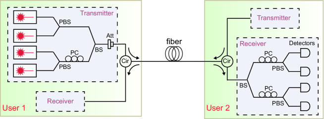
In our network, we used the polarization-encoding BB84 QKD protocol [17, 18, 19] with a vacuum+weak decoy-state method [20] to generate secrete keys between directly connected users and trusted relays. Two users could generate keys if one of them had a quantum transmitter and the other had a quantum receiver. As a quantum receiver is generally more expensive compared with a quantum transmitter, not all users in this network possessed quantum receivers. However, everyone at least had a quantum transmitter and was thus able to transmit signals. In this case, there were two types of users in this network: users directly connected to a switch have both quantum a transmitter and receiver, and users directly connected to a trusted relay have only a quantum transmitter. There were, correspondingly, two types of equipment: one only for transmitting signals and the other for transmitting and receiving signals at the same time.
Standard transmitter and receivers are applied in our network, whose internal structures are shown in Fig. 2. In the transmitters, we use the -pin butterfly distribute feedback lasers with central wavelength nm. Polarization states {, , , } are produced with four different lasers, where each one can produce three different intensity pulses corresponding to the signal, decoy, and vacuum states. Before key generation, a time calibration between the source and the single-photon detectors as well as polarization feedback is performed. In general, the calibration is more efficient with strong pulses. It will take more time to complete the calibration for longer transmission distance but no more than 5 minutes. The calibration process makes our network robust against environmental disturbances. After basis reconciliation and error correction, privacy amplification is performed after kbit per second (kbps) keys are accumulated. Based on a field-programmable gate array (FPGA), the Winnow algorithm [21] is used for error correction, with a correction efficiency of . Then, privacy amplification is performed using an FPGA implemented Toeplitz matrix Hash operation [22], which is constructed by true random numbers shared by the transmitter and receiver devices. The standardization of the QKD equipment can greatly reduce the amount of devices required: allowing the number of devices scales linearly with the number of user nodes.
Key management
A key management strategy enables the users whose keys are running out to generate keys in high priority. We realise systematic key management for our network by designing a switching strategy. The strategy is determined by the amount of keys stored in the local memories for the users. The user with the least key amount has priority in the queue for key distribution. Here we take the -port all-pass optical switch mentioned above as an example. Since it can be connected to users, there are a total of possible key pairing schemes by which two users are connected for the following QKD process. The queuing process for the key pairing scheme is determined by the Roll-Call-Polling protocol that judges the amount of keys between users. When the key amounts of all devices are the same, QKD pairing is sequentially performed in the order of the network ID. For arbitrary communication partners, the latency for key pairing is heuristically set to be , or minutes according to experience. Then the optical paths of the optical switch are connected, and the QKD process begins. Such a pairing process will repeat whenever there are QKD tasks. The switching time can be configured, ranging from to minutes. If two users in different subnetworks wish to perform QKD, they first generate keys with intermediate nodes and then swap them. After key generation is activated, the user can obtain secure keys within minutes, which are stored in local memories.
Since our network is scalable, we also need to consider the key management for new users. To join the network, a new user should first send a heartbeat frame from their QKD device to the key management server, i.e., its upstream optical switch or trusted relay node. A sequence of kbit initial keys with the trusted relay or optical switch is used for authentication. The authentication is implemented by the HMAC algorithm based on the symmetric key algorithm SM4 [23], which does not provide information-theoretic security. Within minutes after power-on, the QKD device is connected to the network. Then, the device is in the queue for key generation.
Security analysis
We follow the standard decoy state BB84 security analysis [18, 20] and its finite size analysis [24]. The secret key rate of the BB84 protocol is given by [25, 18],
| (1) |
where is the error correction efficiency, is the mean photon number per pulse for a signal state, is the overall gain for the signal states, is the quantum bit error rate (QBER), , are the yield and phase error rate of the single photon component and is the binary Shannon entropy function. The single photon yield and phase error rate can be well estimated by the decoy state method [18]. In fact, only three intensities (signal, weak decoy and vacuum) are enough to give tight bounds [20], as implemented in our network.
In the finite size case, there will be deviations in the estimations of parameters above due to the statistical fluctuations. The main finite-size effect comes from the phase error rate estimation [24]. Suppose we use -basis states to generate key, then the single photon phase error rate in this basis is bounded by the single photon bit error rate in basis and a small deviation optimized according to experimental data [24],
| (2) |
with a failure probability of
| (3) |
where and are the numbers of bits measured in and basis, respectively, and . There will also be failure probabilities in other steps including the authentication, error verification, and privacy amplification. These failure probabilities are functions of the secure key consumption in the corresponding steps, and have additivity due to the composable security. In the Supplementary Note 2, we will show how to calculate the finite-size key rate in detail.
Application
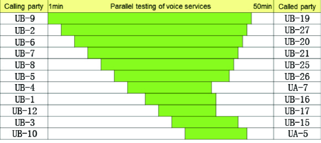
For applications of our network, users could make use of the generated secure keys to confidentially transfer information. The message is encoded in FPGA modules with an exclusive or operation on the secure keys. We apply our network to transmit encrypted information such as real-time voice telephone, instant messaging, and digital files with the one-time pad encryption method [26]. The total amount of information to be encrypted is Gbits. The encryption speed is Mbps. The total delay in the encryption process is less than us. In our network, the speed of real-time voice telephone was kbps, the speed of file transmission was 320 kbps. The capacity of our network is tested for minutes, as shown in Fig. 3. 22 users simultaneously made calls in the quantum network for minutes (see Supplementary Note 1 for more details).
Network robustness
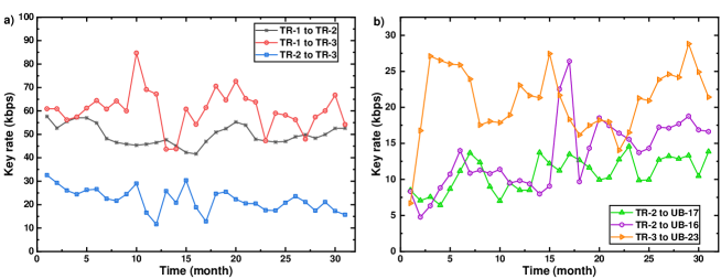
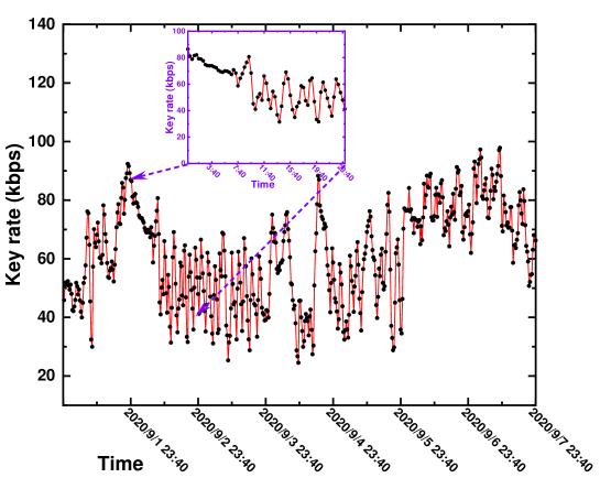
In addition, the stability and robustness of the network were tested by running continuously for 31 months. We choose some representative nodes and show the key rates versus time in Fig. 4. The key rate results are summarized in Table 2, ranging from to kbps. Since the Hefei network is based on the Roll-Call-Polling protocol, the results are all average key rates during the QKD process. The key rate fluctuation mainly comes from the fast variations of photon polarization, which is determined by the internal structure and surrounding environment of the optical fiber. The error rate caused by the variations of photon polarization will accumulate with the propagation of the photons, leading to a drop of the key rate. Once the error rate is high enough, the QKD process is aborted and calibration is performed. Then the key rate will return to a normal value, corresponding to the ascensions in key rate performance.
| TR1-TR2 | TR1-TR3 | TR2-TR3 | |
|---|---|---|---|
| Average key rate (kbps) | |||
| TR1 Subnetwork | TR2 Subnetwork | TR3 Subnetwork | |
| Key rate range (kbps) |
Discussion
In summary, we have presented a practical, large-scale metropolitan QKD network with standard commercial QKD products, systematic key management, and practical usage in Hefei, China. This quantum network can be scaled by adding more users and relays, and it can be connected to the Shanghai–Beijing backbone to become a national network. Our network can be combined with other QKD protocols that are robust against device imperfections. For instance, to overcome the imperfection of measurement devices, measurement-device-independent (MDI) QKD protocols [27] can be employed. In experiment, the MDI-QKD protocol has been extensively verified and an MDI-QKD network over unreliable metropolitan has been recently realized [28]. Combined with the MDI-QKD network, one can imagine that communication in the future can be done in both efficient and secure way. Recently an inter-continental QKD network was reported [15], connecting several metropolitan networks with a satellite. Our practical implementations and applications of a metropolitan network can be well combined with [15] for future directions.
Acknowledgments
The authors acknowledge insightful discussions with Z. Zhang. This work was supported by the National Key Research and Development Program of China (2017YFA0303903), Anhui Initiative in Quantum Information Technologies, and the Chinese Academy of Sciences. The authors also acknowledge support from the Anhui Provincial Government, the Hefei City Government, the Hefei Broadcast & TV Broad Band Network Ltd.
Supplementary Information
Supplementary Note 1: Experiment Details
.0.1 Details of the experimental parameters
Due to the finite polarization contrast and the dark counts of single photon detectors, a sifted key can differ between Alice and Bob after basis comparison. These keys must be reconciled using classical error correction. In a QKD system, we use a field-programmable gate array (FPGA) based Winnow error correction algorithm with efficiency of , and the reconciliation takes less than ms for a sifted key of kbits, when the bit error rate is less than %. After error correction, we apply a cyclic redundancy check (CRC). If the CRC passes, the key string is retained; otherwise, it is abandoned.
We use lasers as a light source in this system. However, doing so results in multi-photon constituents that could be used by eavesdroppers. Fortunately, we can reduce the amount of leaked information via privacy amplification. We estimate the secure factor using the decoy method. Privacy amplification is completely implemented in FPGA by a Toeplitz matrix. During the matrix multiplication process, we use block operations because the matrix is very large. The large matrix is divided into many smaller blocks; we can multiply two blocks in one clock cycle using parallel arithmetic. Note that the finite key effect is considered in the parameter estimation.
With the aid of automated monitoring and control, our system can run consistently for a long time. For instance, at a fibre length of km, the quantum bit error rate is generally below %, and the QKD systems can reach a key rate of kbps when running in both directions. The clock rate of our system is 20 MHz and is updated to MHz for the robustness test. The total loss includes that caused by the fibres, which is proportional to one fourth of their length in units of kilometers, as well as the inherent loss of the detector, which is about dB, and the efficiency of the detectors, which is about %.
.0.2 Details of the calibration
The calibration of the QKD systems is performed in three main steps. Here all the optical pulses are strong pulses and not at single-photon level. The first step is associated with detector gate time calibration, where Alice’s lasers sends optical pulses of MHz, and when the photon count rate, , , , and , of the four single photon detectors reach the maximum simultaneously, a visibility () is calculated. The gate positions of the detectors are scanned to maximize this visibility. The lowest value allowed for the QKD systems in this network is %. If the visibility is lower than this value for 3 times in a row for any detector, the calibration is aborted.
The second step is associated with polarization feedback. Specifically, it begins with Alice’s sending polarization laser pulses at MHz to Bob. Bob adjusts his electrical polarization controllers to maximize the visibility. The minimum value of the polarization visibility permitted by the systems in the Hefei network is set to be dB. If the measured value is lower than this value, the electrical polarization controllers are initialized and scanned again. Once the polarization calibration for passes, Alice immediately switches the laser off and send pulses to verify the latter’s polarization visibility, which should be around the same value as . The process is repeated for the and polarization pulses, and the calibration is aborted after 3 failed trials.
In the final step the repetition of Alice’s lasers are adjusted to kHz to match the synchronization laser pulses ( kHz, wavelength at nm). The four lasers send pulses to Bob to calibrate the time sequence. If any of the lasers fail to pass the synchronization after 3 consecutive times, the calibration is aborted.
The calibration performs better with stronger pulses. Therefore, when the transmission distance increases, the QKD system needs to increase the laser power. This makes the total calibration time for the three steps vary with the transmission distance. It turn out that the total time is always within 5 minutes.
The main source of noise in our network comes from the slow drifts in field fibers that affects the polarization of the quantum signals. our log file about the feedback calibration time can reflect how fast the noise builds up. For instance, over 24 hours on April 23, 2021, polarization of the TR2-TR3 link was calibrated for times, as shown Table below. As we can see, the polarization was very stable overnight and the QKD system can run steadily for almost hours. Over the daytime, noise was more prominent and polarization was calibrated every minutes.
.0.3 Details of the key management
The network topology is pre-configured on the control center of the network. When each key management device is activated, they will log in the control center for authentication. The control center will control the devices that have already logged in and been authenticated to perform the QKD process and provide relevant necessary information, such as the connection configuration of neighboring devices.
The key will be automatically supplemented for authentication after the consumption. If the keys are lost for some reasons, one needs to manually reset the key. The authentication keys are stored separately, which are used only for identity authentication and cannot be accessed by other services.
We have employed several means to ensure security of the key management devices. For key storage, we encrypt the new secure keys with previously generated keys at the key pools and then store the encrypted keys in the secure modules. With FPGA-based protocols for isolation, these modules are protected against external network attacks. We apply anti-detection design and restrict the electromagnetic radiations.
.0.4 Details of the key rates
Supplementary Note 2: Key Rate Calculation
We take a typical link UB-23 to TR-3 in Supplementary Table 4 as an example to show how to calculate the finite-size key rate with experimental data. We recall the BB84 key rate formula given in the main text,
| (4) |
In our experiment, we apply vacuum and weak decoy state method to estimate the lower bound of and the upper bound of , which are denoted by and , respectively. These bounds are given by [20]
| (5) | ||||
where and are intensities of signal and weak decoy states, respectively, and are gains of signal and weak decoy states, respectively, equals to the dark count rate , and is the error rate of dark counts and equals to . Considering the symmetry of and basis, we do not denote the basis information for the parameters above. One can calculate the bounds above in each basis. Note that is the the upper bound of the bit error rate of the single photon component in or basis. Due to the basis-independence of single photon component, we have and . Then we can directly substitute into Eq. (4) as the upper bound of the phase error rate in asymptotic case.
In finite-size case, we need to consider the deviation between and (or between and ), which is given by the random sampling method [24],
| (6) | ||||
and
| (7) |
where and are the number of sifted key bits in and basis, respectively, and .
We also need to consider the statistical fluctuation in the observed experimental data. Here we assume Gaussian fluctuations and set the fluctuations to be standard deviations, then we have the following bounds for an arbitrary variable
| (8) | ||||
where can be the gain, and , quantum bit error rate in each basis, and , the successful detections for single photon components, and . The last two quantities cannot be directly observed in experiment. They are defined as
| (9) | ||||
where and are the number of and basis states after sifting, and are the probabilities of choosing signal and weak decoy states, respectively. In our case and .
We use the following substitutions in Eqs.(5) and (6) after considering the statistical fluctuation, , , , , and . The finite-key length in basis is given by
| (10) |
where is the total key consumption in the post-processing [24] and is the number of successful detections of -basis signal states. If we take the failure probability in each step as , will be at the order of bits. The finite-key length in basis can be calculated similarly. In our case, we use both basis to generate keys, the total finite-key length is . The key rate is given by , where is the repetition rate of the source.
The values of the parameters of the link UB-23 to TR-3 in the key rate calculation are listed in Supplementary Table 9, with which we can calculate the finite-size key rate in Supplementary Table 4. In the future, we will update the key rate calculation module with the Chernoff-Hoeffding method in our system.
Supplementary Figures and Tables
| Polarization Calibration Time | Calibration Interval |
|---|---|
| (hour:minute:second) | (hour:minute:second) |
| — | |
| Transmitter | Receiver | Key rate | Transmitter | Receiver | Key rate |
|---|---|---|---|---|---|
| TR-3 | TR-1 | 19.8 | UA-10 | UA-8 | 20 |
| TR-2 | 61.4 | UA-9 | 32 | ||
| UB-18 | TR-3 | 7 | UA-11 | 30 | |
| UB-19 | 12 | UA-12 | 37 | ||
| UB-20 | 10 | UA-13 | 32 | ||
| UB-21 | 9 | TR-3 | 8 | ||
| UB-22 | 10 | UA-11 | UA-8 | 21 | |
| UB-23 | 18 | UA-9 | 20 | ||
| UB-24 | 8 | UA-10 | 30 | ||
| UB-25 | 11 | UA-12 | 19 | ||
| UB-26 | 18 | UA-13 | 26 | ||
| UB-27 | 8 | TR-3 | 9 | ||
| UA-8 | UA-9 | 19 | UA-12 | UA-8 | 20 |
| UA-10 | 20 | UA-9 | 24 | ||
| UA-11 | 21 | UA-10 | 37 | ||
| UA-12 | 20 | UA-11 | 19 | ||
| UA-13 | 22 | UA-13 | 33 | ||
| TR-3 | 10 | TR-3 | 6 | ||
| UA-9 | UA-8 | 19 | UA-13 | UA-8 | 22 |
| UA-10 | 32 | UA-9 | 25 | ||
| UA-11 | 20 | UA-10 | 32 | ||
| UA-12 | 24 | UA-11 | 26 | ||
| UA-13 | 25 | UA-12 | 33 | ||
| TR-3 | 10 | TR-3 | 28 |
| Transmitter | Receiver | Key rate | Transmitter | Receiver | Key rate |
|---|---|---|---|---|---|
| TR-2 | TR-1 | 23.7 | UA-3 | UA-1 | 18 |
| TR-3 | 54.4 | UA-2 | 24 | ||
| UB-13 | TR-2 | 13 | UA-4 | 19 | |
| UB-14 | 17 | UA-5 | 28 | ||
| UB-15 | 12 | TR-2 | 17 | ||
| UB-16 | 16 | UA-4 | UA-1 | 11 | |
| UB-17 | 21 | UA-2 | 11 | ||
| UA-1 | UA-2 | 17 | UA-3 | 19 | |
| UA-3 | 18 | UA-5 | 25 | ||
| UA-4 | 11 | TR-2 | 27 | ||
| UA-5 | 10 | UA-5 | UA-1 | 10 | |
| TR-2 | 30 | UA-2 | 21 | ||
| UA-2 | UA-1 | 17 | UA-3 | 28 | |
| UA-3 | 24 | UA-4 | 25 | ||
| UA-4 | 11 | TR-2 | 16 | ||
| UA-5 | 21 | UA-6 | UA-7 | 11 | |
| TR-2 | 11 | TR-2 | 10 | ||
| UA-7 | UA-6 | 11 | UA-7 | TR-2 | 13 |
| Transmitter | Receiver | Key rate |
| TR-1 | TR-2 | 7.8 |
| TR-3 | 49.5 | |
| UB-1 | TR-1 | 6 |
| UB-2 | 16 | |
| UB-3 | 17 | |
| UB-4 | 16 | |
| UB-5 | 9 | |
| UB-6 | 17 | |
| UB-7 | 9 | |
| UB-8 | 17 | |
| UB-9 | 6 | |
| UB-10 | 8 | |
| UB-11 | 14 | |
| UB-12 | 12 |
| Time (month) | TR-2 | ||||
|---|---|---|---|---|---|
| UB-13 | UB-16 | UB-14 | UB-15 | UB-17 | |
| 1 | 26.1 | 8.3 | 11.4 | 35.6 | 8.5 |
| 2 | 32.9 | 4.8 | 18.5 | 35.0 | 7.1 |
| 3 | 39.1 | 6.4 | 22.8 | 45.5 | 7.6 |
| 4 | 38.6 | 8.8 | 20.2 | 47.8 | 6.4 |
| 5 | 44.8 | 10.7 | 23.9 | 48.4 | 8.7 |
| 6 | 47.4 | 14.0 | 23.8 | 56.8 | 11.2 |
| 7 | 37.6 | 10.9 | 19.0 | 50.6 | 13.7 |
| 8 | 46.8 | 11.3 | 13.7 | 53.4 | 12.4 |
| 9 | 45.0 | 10.8 | 12.3 | 54.5 | 9.0 |
| 10 | 58.4 | 11.4 | 10.4 | 55.1 | 7.0 |
| 11 | 49.4 | 9.5 | 11.4 | 56.1 | 9.5 |
| 12 | 49.0 | 9.8 | 5.6 | 56.8 | 8.5 |
| 13 | 48.2 | 9.4 | 7.2 | 15.1 | 8.5 |
| 14 | 71.4 | 8.0 | 8.1 | 27.3 | 13.7 |
| 15 | 53.4 | 9.1 | 9.8 | 21.7 | 12.2 |
| 16 | 57.1 | 22.5 | 8.0 | 56.1 | 11.2 |
| 17 | 55.9 | 26.4 | 3.4 | 56.1 | 13.5 |
| 18 | 53.5 | 9.7 | 5.3 | 60.4 | 12.7 |
| 19 | 33.9 | 14.3 | 5.1 | 53.9 | 11.6 |
| 20 | 45.3 | 18.5 | 4.2 | 58.4 | 9.9 |
| 21 | 50.4 | 17.5 | 6.1 | 59.8 | 10.3 |
| 22 | 45.4 | 16.4 | 7.3 | 58.1 | 12.8 |
| 23 | 31.4 | 15.6 | 6.9 | 57.4 | 14.6 |
| 24 | 44.7 | 13.7 | 9.0 | 57.8 | 9.9 |
| 25 | 55.1 | 14.3 | 12.7 | 50.5 | 9.9 |
| 26 | 38.2 | 17.2 | 14.7 | 54.5 | 12.7 |
| 27 | 43.7 | 17.1 | 16.8 | 56.3 | 13.2 |
| 28 | 39.5 | 17.7 | 15.2 | 56.1 | 12.9 |
| 29 | 37.3 | 18.8 | 16.5 | 55.1 | 13.3 |
| 30 | 35.0 | 16.9 | 13.6 | 52.0 | 10.5 |
| 31 | 35.0 | 16.6 | 14.0 | 50.1 | 13.9 |
| Time (month) | TR-3 | |||||
|---|---|---|---|---|---|---|
| UB-19 | UB-20 | UB-21 | UB-22 | UB-23 | UB-24 | |
| 1 | 7.7 | 34.7 | 19.3 | 29.9 | 6.7 | 8.5 |
| 2 | 6.0 | 30.7 | 22.2 | 27.1 | 16.8 | 41.6 |
| 3 | 9.9 | 31.1 | 22.2 | 25.1 | 27.1 | 47.5 |
| 4 | 8.7 | 30.7 | 19.4 | 26.3 | 26.5 | 46.9 |
| 5 | 8.3 | 31.1 | 21.5 | 28.4 | 26.0 | 45.3 |
| 6 | 10.3 | 30.5 | 22.7 | 30.5 | 25.9 | 42.8 |
| 7 | 5.9 | 24.8 | 19.9 | 35.9 | 23.9 | 40.0 |
| 8 | 8.7 | 26.0 | 18.7 | 51.2 | 17.6 | 52.3 |
| 9 | 9.7 | 26.8 | 20.1 | 51.6 | 18.1 | 44.0 |
| 10 | 8.4 | 24.7 | 22.1 | 44.5 | 17.9 | 35.8 |
| 11 | 8.3 | 32.0 | 21.1 | 53.8 | 18.9 | 43.6 |
| 12 | 10.0 | 30.0 | 19.4 | 54.7 | 23.1 | 44.9 |
| 13 | 8.5 | 27.4 | 16.6 | 47.9 | 21.6 | 54.8 |
| 14 | 10.0 | 29.4 | 16.7 | 51.7 | 21.3 | 42.3 |
| 15 | 8.3 | 23.3 | 22.8 | 55.1 | 27.5 | 53.1 |
| 16 | 7.0 | 28.7 | 21.4 | 39.1 | 21.7 | 45.9 |
| 17 | 7.1 | 29.6 | 22.7 | 38.3 | 18.3 | 37.4 |
| 18 | 4.6 | 29.6 | 21.0 | 41.8 | 16.2 | 41.5 |
| 19 | 6.4 | 28.0 | 19.7 | 35.4 | 17.5 | 45.1 |
| 20 | 3.9 | 32.6 | 20.1 | 46.8 | 18.2 | 43.9 |
| 21 | 6.3 | 32.6 | 20.3 | 45.2 | 18.0 | 40.5 |
| 22 | 7.2 | 27.9 | 17.1 | 38.3 | 14.0 | 37.0 |
| 23 | 9.0 | 22.6 | 15.1 | 40.3 | 16.5 | 37.3 |
| 24 | 7.3 | 24.7 | 16.5 | 38.0 | 21.3 | 42.5 |
| 25 | 7.4 | 28.4 | 15.0 | 35.0 | 20.9 | 39.5 |
| 26 | 7.0 | 26.6 | 14.1 | 36.5 | 23.8 | 41.9 |
| 27 | 7.7 | 24.3 | 15.3 | 38.2 | 24.6 | 41.6 |
| 28 | 8.6 | 20.4 | 13.4 | 40.7 | 24.2 | 40.1 |
| 29 | 8.3 | 22.8 | 14.0 | 36.6 | 28.8 | 36.8 |
| 30 | 7.3 | 13.5 | 16.2 | 37.8 | 24.9 | 32.9 |
| 31 | 7.2 | 19.6 | 16.6 | 42.9 | 21.4 | 26.6 |
| MHz |
References
- Bennett and Brassard [1984] C. H. Bennett and G. Brassard, Quantum cryptography: Public key distribution and coin tossing, in Proceedings of IEEE International Conference on Computers, Systems, and Signal Processing (IEEE, New York, 1984) pp. 175–179.
- Ekert [1991] A. K. Ekert, Quantum cryptography based on bell’s theorem, Phys. Rev. Lett. 67, 661 (1991).
- Ursin et al. [2007] R. Ursin, F. Tiefenbacher, T. Schmitt-Manderbach, H. Weier, T. Scheidl, M. Lindenthal, B. Blauensteiner, T. Jennewein, J. Perdigues, P. Trojek, et al., Entanglement-based quantum communication over 144 km, Nature Phys. 3, 481 (2007).
- Takesue et al. [2007] H. Takesue, S. W. Nam, Q. Zhang, R. H. Hadfield, T. Honjo, K. Tamaki, and Y. Yamamoto, Quantum key distribution over a 40-db channel loss using superconducting single-photon detectors, Nat. Photon. 1, 343 (2007).
- Nauerth et al. [2013] S. Nauerth, F. Moll, M. Rau, C. Fuchs, J. Horwath, S. Frick, and H. Weinfurter, Air-to-ground quantum communication, Nat. Photon. 7, 382 (2013).
- Wang et al. [2013] J.-Y. Wang, B. Yang, S.-K. Liao, L. Zhang, Q. Shen, X.-F. Hu, J.-C. Wu, S.-J. Yang, H. Jiang, Y.-L. Tang, et al., Direct and full-scale experimental verifications towards ground-satellite quantum key distribution, Nat. Photon. 7, 387 (2013).
- Elliott et al. [2005] C. Elliott, A. Colvin, D. Pearson, O. Pikalo, J. Schlafer, and H. Yeh, Current status of the darpa quantum network, in Quantum Information and computation III, Vol. 5815 (International Society for Optics and Photonics, 2005) pp. 138–150.
- Peev et al. [2009] M. Peev, C. Pacher, R. Alléaume, C. Barreiro, J. Bouda, W. Boxleitner, T. Debuisschert, E. Diamanti, M. Dianati, J. Dynes, et al., The secoqc quantum key distribution network in vienna, New J. Phys. 11, 075001 (2009).
- Stucki et al. [2011] D. Stucki, M. Legré, F. Buntschu, B. Clausen, N. Felber, N. Gisin, L. Henzen, P. Junod, G. Litzistorf, P. Monbaron, L. Monat, J.-B. Page, D. Perroud, G. Ribordy, A. Rochas, S. Robyr, J. Tavares, R. Thew, P. Trinkler, S. Ventura, R. Voirol, N. Walenta, and H. Zbinden, Long-term performance of the SwissQuantum quantum key distribution network in a field environment, New Journal of Physics 13, 123001 (2011).
- Wang et al. [2010] S. Wang, W. Chen, Z.-Q. Yin, Y. Zhang, T. Zhang, H.-W. Li, F.-X. Xu, Z. Zhou, Y. Yang, D.-J. Huang, L.-J. Zhang, F.-Y. Li, D. Liu, Y.-G. Wang, G.-C. Guo, and Z.-F. Han, Field test of wavelength-saving quantum key distribution network, Opt. Lett. 35, 2454 (2010).
- Sasaki et al. [2011] M. Sasaki, M. Fujiwara, H. Ishizuka, W. Klaus, K. Wakui, M. Takeoka, S. Miki, T. Yamashita, Z. Wang, A. Tanaka, K. Yoshino, Y. Nambu, S. Takahashi, A. Tajima, A. Tomita, T. Domeki, T. Hasegawa, Y. Sakai, H. Kobayashi, T. Asai, K. Shimizu, T. Tokura, T. Tsurumaru, M. Matsui, T. Honjo, K. Tamaki, H. Takesue, Y. Tokura, J. F. Dynes, A. R. Dixon, A. W. Sharpe, Z. L. Yuan, A. J. Shields, S. Uchikoga, M. Legré, S. Robyr, P. Trinkler, L. Monat, J.-B. Page, G. Ribordy, A. Poppe, A. Allacher, O. Maurhart, T. Länger, M. Peev, and A. Zeilinger, Field test of quantum key distribution in the tokyo qkd network, Opt. Express 19, 10387 (2011).
- Chen et al. [2009] T.-Y. Chen, H. Liang, Y. Liu, W.-Q. Cai, L. Ju, W.-Y. Liu, J. Wang, H. Yin, K. Chen, Z.-B. Chen, C.-Z. Peng, and J.-W. Pan, Field test of a practical secure communication network with decoy-state quantum cryptography, Optics Express 17, 6540 (2009).
- Chen et al. [2010] T.-Y. Chen, J. Wang, H. Liang, W.-Y. Liu, Y. Liu, X. Jiang, Y. Wang, X. Wan, W.-Q. Cai, L. Ju, L.-K. Chen, L.-J. Wang, Y. Gao, K. Chen, C.-Z. Peng, Z.-B. Chen, and J.-W. Pan, Metropolitan all-pass and inter-city quantum communication network, Optics Express 18, 27217 (2010).
- Liao et al. [2018] S.-K. Liao, W.-Q. Cai, J. Handsteiner, B. Liu, J. Yin, L. Zhang, D. Rauch, M. Fink, J.-G. Ren, W.-Y. Liu, Y. Li, Q. Shen, Y. Cao, F.-Z. Li, J.-F. Wang, Y.-M. Huang, L. Deng, T. Xi, L. Ma, T. Hu, L. Li, N.-L. Liu, F. Koidl, P. Wang, Y.-A. Chen, X.-B. Wang, M. Steindorfer, G. Kirchner, C.-Y. Lu, R. Shu, R. Ursin, T. Scheidl, C.-Z. Peng, J.-Y. Wang, A. Zeilinger, and J.-W. Pan, Satellite-relayed intercontinental quantum network, Phys. Rev. Lett. 120, 030501 (2018).
- Chen et al. [2021] Y.-A. Chen, Q. Zhang, T.-Y. Chen, W.-Q. Cai, S.-K. Liao, J. Zhang, K. Chen, J. Yin, J.-G. Ren, Z. Chen, S.-L. Han, Q. Yu, K. Liang, F. Zhou, X. Yuan, M.-S. Zhao, T.-Y. Wang, X. Jiang, L. Zhang, W.-Y. Liu, Y. Li, Q. Shen, Y. Cao, C.-Y. Lu, R. Shu, J.-Y. Wang, L. Li, N.-L. Liu, F. Xu, X.-B. Wang, C.-Z. Peng, and J.-W. Pan, An integrated space-to-ground quantum communication network over 4,600 kilometres, Nature 589, 214 (2021).
- Xu et al. [2020] F. Xu, X. Ma, Q. Zhang, H.-K. Lo, and J.-W. Pan, Secure quantum key distribution with realistic devices, Rev. Mod. Phys. 92, 025002 (2020).
- Hwang [2003] W.-Y. Hwang, Quantum key distribution with high loss: Toward global secure communication, Phys. Rev. Lett. 91, 057901 (2003).
- Lo et al. [2005] H.-K. Lo, X. Ma, and K. Chen, Decoy state quantum key distribution, Phys. Rev. Lett. 94, 230504 (2005).
- Wang [2005] X.-B. Wang, Beating the photon-number-splitting attack in practical quantum cryptography, Phys. Rev. Lett. 94, 230503 (2005).
- Ma et al. [2005] X. Ma, B. Qi, Y. Zhao, and H.-K. Lo, Practical decoy state for quantum key distribution, Phys. Rev. A 72, 012326 (2005).
- Buttler et al. [2003] W. T. Buttler, S. K. Lamoreaux, J. R. Torgerson, G. H. Nickel, C. H. Donahue, and C. G. Peterson, Fast, efficient error reconciliation for quantum cryptography, Phys. Rev. A 67, 052303 (2003).
- Krawczyk [1995] H. Krawczyk, New hash functions for message authentication, in International Conference on the Theory and Applications of Cryptographic Techniques (Springer, 1995) pp. 301–310.
- Krawczyk et al. [1997] H. Krawczyk, M. Bellare, and R. Canetti, Hmac: Keyed-hashing for message authentication (1997).
- Fung et al. [2010] C.-H. F. Fung, X. Ma, and H. F. Chau, Practical issues in quantum-key-distribution postprocessing, Phys. Rev. A 81, 012318 (2010).
- Gottesman et al. [2004] D. Gottesman, H.-K. Lo, N. Lutkenhaus, and J. Preskill, Security of quantum key distribution with imperfect devices, in International Symposium onInformation Theory, 2004. ISIT 2004. Proceedings. (IEEE, 2004) p. 136.
- Shannon [1949] C. E. Shannon, Communication theory of secrecy systems, Bell system technical journal 28, 656 (1949).
- Lo et al. [2012] H.-K. Lo, M. Curty, and B. Qi, Measurement-device-independent quantum key distribution, Phys. Rev. Lett. 108, 130503 (2012).
- Tang et al. [2016] Y.-L. Tang, H.-L. Yin, Q. Zhao, H. Liu, X.-X. Sun, M.-Q. Huang, W.-J. Zhang, S.-J. Chen, L. Zhang, L.-X. You, Z. Wang, Y. Liu, C.-Y. Lu, X. Jiang, X. Ma, Q. Zhang, T.-Y. Chen, and J.-W. Pan, Measurement-device-independent quantum key distribution over untrustful metropolitan network, Phys. Rev. X 6, 011024 (2016).