A Cooper-Pair Box Coupled to Two Resonators: An Architecture for a Quantum Refrigerator
Abstract
Superconducting circuits present a promising platform with which to realize a quantum refrigerator. Motivated by this, we fabricate and perform spectroscopy of a gated Cooper-pair box, capacitively coupled to two superconducting coplanar waveguide resonators with different frequencies. We experimentally demonstrate the strong coupling of a charge qubit to two superconducting resonators, with the ability to perform voltage driving of the qubit at frequencies. We go on to discuss how the measured device could be modified to operate as a cyclic quantum refrigerator by terminating the resonators with normal-metal resistors acting as heat baths.
I Introduction
The study of quantum heat engines and refrigerators plays a key role in the investigation of the fundamental relationship between quantum mechanics and thermodynamics Kosloff and Levy (2014); Alicki (1979); Quan et al. (2007); Binder et al. (2019). However, experimental realizations of cyclic quantum thermal engines have remained elusive. Such systems, in their most basic form, consist of a working substance with quantized energy levels which can be selectively coupled to a series of thermal reservoirs, and are capable of transporting heat Kosloff (2013). By modulation of the working substance energy-level separation, for example, the system can be tuned to interact with each thermal reservoir sequentially. Moreover, by periodic modulation of the system energy levels, a quantum heat engine, or quantum refrigerator can be actualized Karimi and Pekola (2016); Niskanen et al. (2007).
A multitude of platforms have been proposed and explored to realize quantum thermal machines. In a seminal paper Roßnagel et al. (2016), an ion held in a linear Pauli trap was used to extract work by alternate exposure between a white noise electric field (hot reservoir), and a laser cooling beam (cold reservoir). More recently, a solid state quantum dot was operated as a ‘particle exchange’ heat engine, where the dot can control a thermally driven flow of charge carriers Josefsson et al. (2018). In a further development, a 13C nuclear spin has been utilized to implement an Otto cycle using a nuclear magnetic resonance setup Peterson et al. (2019). Additionally, an electron spin impurity has been shown to act as an analogue heat-engine, with the ‘thermal’ reservoirs inferred by the relative chemical potential in the leads Ono et al. (2020). However, in all such systems the heat current cannot be probed directly, and must be inferred from an additional parameter.
Circuit quantum electrodynamics (c-QED) using superconducting qubits remains a highly promising platform for realizing such a thermal machine, owing largely to the exceptional control which experimentalists have over the collective quantum degrees of freedom You and Nori (2005); Gu et al. (2017); Kjaergaard et al. (2020). c-QED has enjoyed a striking period of advancement, with numerous studies demonstrating strong coupling of photons to various types of qubits Wallraff et al. (2004); Blais et al. (2004); Schuster et al. (2007), with a broad range of applications Clarke and Wilhelm (2008); Montanaro (2016); Wendin (2017). Furthermore, modern nanofabrication techniques allow the integration and characterization of superconducting qubits coupled to normal-metal dissipative elements Chang et al. (2019), creating hybrid c-QED systems capable of probing thermal transport in quantum systems. Such systems differentiate themselves from previous attempts on quantum heat engines via their unambiguous implementation of thermal reservoirs, which naturally define the bath temperature, and possess a multitude of techniques for both primary and secondary thermometry Giazotto et al. (2006); Pekola and Karimi (2021).
Superconducting quantum circuits involving dissipative elements have already platformed several pioneering experiments in quantum heat transport. A transmon qubit coupled to two superconducting resonators, terminated by normal metal resistors was used to measure DC heat transport modulated by magnetic flux threading a superconducting quantum interference (SQUID) loop. By using both identical and non-identical resonator frequencies, this led to the realization of a quantum heat valve Ronzani et al. (2018) and a quantum heat rectifier Senior et al. (2020). Despite the remarkable control exhibited by such systems, GHz-frequency cyclic driving of transmon qubits has proven experimentally difficult due to the large power dissipated by on-chip magnetic flux bias lines. Additionally, the performance of transmon qubits in thermal systems is limited by the relatively weak anharmonicity due to the large ratio of Josephson energy to charging energy, . Weak anharmonicity removes the ability to properly isolate a qubit transition, meaning contributions from higher energy levels create undesired parasitic coupling Senior et al. (2020). Moreover, the relatively long coherence time of a transmon qubit, a key asset in quantum information applications, can limit the performance of cyclic quantum engines due to the buildup of coherences in a process known as ‘quantum friction’ Camati et al. (2019); Insinga (2020). The theoretical operation of qubits as thermal machines has been explored extensively, with promising proposals for implementing both refrigerators Kloc et al. (2021); Abah and Lutz (2016); Brandner and Seifert (2016); Niskanen et al. (2007); Karimi and Pekola (2016); Pekola et al. (2019) and heat engines Hofer et al. (2016); Campisi and Fazio (2016); Quan et al. (2007); Solfanelli et al. (2020); Kieu (2004); Gelbwaser-Klimovsky et al. (2013).
To address the aforementioned problems to realize a cyclic quantum refrigerator a Cooper-pair box (charge qubit), which is isolated from higher energy states and easily modulated by an electric-field, could be used as a working substance. A charge qubit, in its simplest form, consists of a nanoscale superconducting island, grounded though a Josephson junction Nazarov and Blanter (2009). Due to the small island dimension, the qubit frequency can now be tuned via the offset charge, , on the island - controllable via the voltage of a nearby gate. Charge qubits have seen extensive study, both individually Nakamura et al. (1999); Pashkin et al. (2009); Bladh et al. (2005) and embedded in microwave cavities Sillanpää et al. (2006); Astafiev et al. (2007); Kim et al. (2008, 2011). The strong coupling of a single photon to a charge qubit was demonstrated in a pioneering work of c-QED Wallraff et al. (2004). Furthermore, modulated DC heat transport through a charge sensitive superconducting single electron transistor has been realized and explained with a simple theoretical model Maillet et al. (2020). Charge qubits have experienced diminishing popularity in recent years since their charge sensitivity Koch et al. (2007) leads to high dephasing rates in quantum information applications. Nonetheless, their charge sensitive properties could be exploited to create an efficient working substance which can be operated with remarkably small input signals. We further note that a charge sensitive qubit connecting two cavity resonators could be a fundamental component in the field of quantum information processing. The setup could allow interactions between distant transmon qubits to be controlled using voltage gates rather than magnetic flux lines - significantly reducing the power required to realize two-qubit gates, compared to tunable flux qubits or SQUIDs Stassi et al. (2020).
In this work, we experimentally demonstrate a charge sensitive qubit capacitively coupled to two resonators of differing frequency. We utilize a charge qubit consisting of an thick and long superconducting island connected to ground through a single-Josephson junction. Using a single junction, rather than the more common two junction SQUID approach, allows us to achieve higher whilst reducing the sensitivity of the qubit frequency to stray magnetic fields. Furthermore, we implement the ability for GHz driving of the qubit via an on-chip voltage gate in close proximity. Through a novel gate-line filtering scheme, we can prevent microwave leakage from the resonators, and decay of the qubit, whilst maintaining the ability to drive at GHz frequencies. Our results show that, despite the sub-m island dimensions, we can realize strong coupling of the qubit with two high-Q resonators without creating any spurious hybridized modes of the system. We go on to discuss how the measured device could be modified to operate as a quantum refrigerator, and perform numerical simulations using a Markovian master equation Lindblad (1976); Heinz-Peter Breuer (2007).
II Cooper-Pair Box coupled to Two Resonators
We consider a charge qubit operating deep in the charge sensitive regime () which couples with two resonators with different frequency. Here, the energy states correspond closely to the charge states, , on the island, and the Hamiltonian of the bare qubit is given by Nazarov and Blanter (2009)
| (1) | ||||
where is the dimensionless offset charge controlled by the nearby gate voltage , with capacitance . At sufficiently low temperature and with restricted around the degeneracy point (), we can consider only two charge states: and , and approximate the charge qubit Hamiltonian as a two-level system, described by
| (2) |
where are the corresponding Pauli matrices in the charge basis. The energy transition of the qubit will be
| (3) |
The qubit interacts capacitively with both voltage antinodes of two quarter wavelength resonators. The Hamiltonian of each resonator is for , with the qubit-resonator interaction terms given by Blais et al. (2004)
| (4) |
where is the qubit mixing angle. The atom cavity coupling at the degeneracy point is determined by the zero-point energy fluctuations of the cavity electric potential, and given by Koch et al. (2007)
| (5) |
where , are the coupler-island and island total capacitances respectively, is the resonator length, and is the capacitance per unit length. By adding a term accounting for the resonator-resonator coupling, , the full system Hamiltonian is therefore
| (6) |
Operating close to the degeneracy point the full Hamiltonian can be reduced to a simplified two-cavity Jaynes-Cummings-type Hamiltonian. The effective coupling strength , i.e., the coupling strength when operating away from the degeneracy point in resonance with the respective resonator, is reduced by a factor in this framework. By implementing a time dependent field, the qubit transition frequency can be cyclically modulated to interact back and forth between the two resonators and .
III Experimental Setup and Device
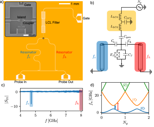
The measured device consists of a charge qubit, formed by a superconducting island connected to ground through a tunnel junction, capacitively coupled to two quarter wavelength, coplanar waveguide (CPW) resonators. A render of the device layout, along with the equivalent circuit, is shown in Fig. 1(a) and Fig. 1(b). Figure 1(b) is depicted without the feedline. We fabricate the device on a thick and high-resistive silicon wafer. Ground-planes, feedlines, couplers and resonators are formed by reactive ion etching of a niobium (Nb) film. The qubit is then formed using a Dolan bridge technique to deposit two layers of aluminum (Al), with an in-situ oxidation to form the tunnel junction. The Nb surface is milled in-situ to ensure a clean contact between the Al and Nb film. Further detail on the fabrication procedure can be found in App. A.
The inset of Fig. 1(a) presents a scanning electron micrograph of the qubit, showing the superconducting island, two Nb couplers and gate line. The Josephson energy, is controlled via the parameters of the oxidation, and can be estimated by measuring the normal-state resistance () of replica junctions fabricated alongside the main structures. By using fork-shaped coupling structures on either side of the small superconducting island we maximize the coupling strength by increasing the ratio , as shown in Eq. (5). Using COMSOL simulations we estimate the capacitances to be , , and the measured , allowing a remarkable to be achieved each, competitively large even when compared with single-resonator systems Astafiev et al. (2007); Koch et al. (2007).
The two resonators are terminated to ground close to a common feedline, creating inductive coupling to allow excitation and readout. By coupling both resonators to a single feedline, we perform single-tone spectroscopy of the qubit in a wide frequency range, confirming the interaction of the qubit with each resonator. The resonators are read out through a notch-type measurement, by measuring the scattering parameter, Probst et al. (2015). Both resonators are overcoupled to the feedline (i.e. the coupling quality factor is less than the internal quality factor ), to allow straightforward measurements in the single-photon regime. All measurements are performed in a cryogen-free dilution refrigerator, with a base temperature . A detailed diagram and further description of the measurement setup can be found in App. B. Figure 1(c) shows the calibrated data as measured through the common feedline. Calibration is performed by measuring the same sample close to the critical temperature of the Nb film, and then correcting via plotting . In this way, impedance mismatches due to the circuit are removed and only the temperature dependent resonator structures remain. We can identify two peaks at and , corresponding to the two resonators. We note the absence of any parasitic or hybridized modes, suggesting the resonator-resonator cross-talk is small.
IV Spectroscopy of the Resonator-Qubit-Resonator System
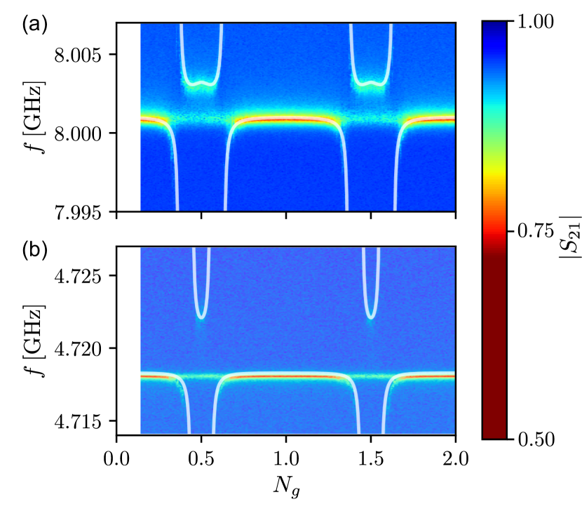
To confirm the interaction of the qubit with each resonator, we perform simultaneous one-tone spectroscopy of the resonator-qubit-resonator system. We use a vector network analyzer (VNA) to probe a frequency, , in the vicinity of the two resonator frequencies, whilst varying the DC gate voltage. The number of photons in the cavity is estimated to be less than in both cases. Figure 2 shows the one-tone spectra in the proximity of the two frequencies, as a function of the dimensionless offset charge, . The Rabi splitting associated with the interaction of a two-level system with a cavity is shown clearly for the high-frequency resonator (Fig. 2(a)) and the low-frequency resonator (Fig. 2(b)). Two periods are presented, symmetrically around . The solid white lines are fits using the numerical solutions to Eq. (6), with , , with excellent agreement with the theoretical model.
In our Cooper-pair box, the spatial profile of the superconducting gap energy is controlled by a thickness difference between the Al-island and Al-lead to suppress the quasiparticle-tunneling rate across the junction Yamamoto et al. (2006). As a result, we observe one-Cooper-pair periodicity of the Rabi splitting in the one-tone spectroscopy. Nevertheless, the poisoning is still expected to be present close to the degeneracy point Aumentado et al. (2004). This poisoning can be observed by the presence of some leftover signal at the cavity frequency in both cases, providing some remaining off-resonance qubit signal Sun et al. (2012); Serniak et al. (2019). We observe this averaging effect because the average parity-switching rate is much shorter than the measurement time. By comparison of the relative amplitudes of the bare resonance signal with that of the remaining signal at the degenerecy we can estimate the parity preference for the odd and even states. We find an even state preference of and in the case of the high-frequency and low-frequency resonators respectively. This could be further mitigated through improved infrared shielding and further quasiparticle engineering Catelani and Pekola (2022). In fact, quasiparticle tunneling is the dominant source of longitudinal relaxation, further discussed in Sec. V.
The relative coupling strengths are measured to be , and . The negligible crosstalk is apparent in Fig. 1(c) from the lack of hybridized modes in the spectrum, and expected due to the vanishing spectral overlap of the two resonators’ Lorentzian functions. We note the relatively weak signals for the dressed states as they move far from the cavity frequency, indicative of the higher dissipation associated with charge sensitive devices when compared with transmon type qubits. Although the raw couplings, , , are large, due to the charge sensitivity the effective couplings are reduced by a factor of , and decrease as we move away from the degeneracy point. We extract the effective coupling strengths by measuring the dispersive shift, , of the resonance at the degeneracy point and calculate by , where is the detuning at degeneracy. The effective coupling strengths are and , corresponding to and of the resonance frequency respectively. Furthermore, the extracted and can be confirmed experimentally using a two-tone spectroscopy technique, to probe the exact qubit transition in the vicinity of the degeneracy point, discussed in detail in Sec. V.
Importantly, due to the large and in the measured device, we can achieve qubit control in a large frequency range using remarkably small signals. Based upon the measured system parameters, the qubit could be driven sinusoidally between the two resonators using a signal amplitude , corresponding to just power at . This presents a four orders-of-magnitude improvement over a comparable driving scheme using an on-chip magnetic flux bias line. The presented data is, to the authors knowledge, the first use of a charge sensitive qubit as a coupling element between two superconducting resonators.
V Decoherence of the Charge Qubit
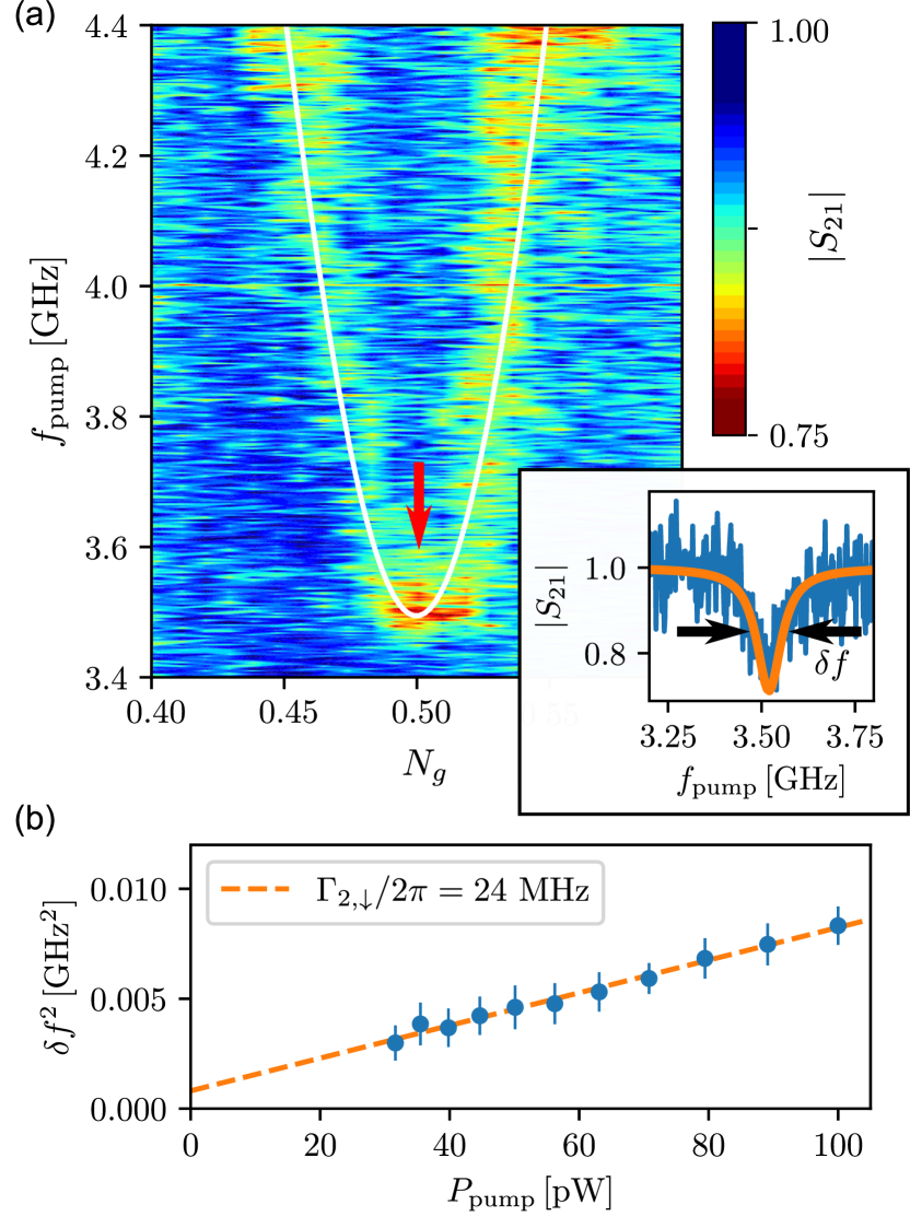
In order to quantify the qubit decoherence and to map the two lowest energy levels of the Cooper-pair box, two-tone spectroscopy is performed. The transmission, , of a weak microwave signal (probe signal) is continuously measured by a VNA located at room temperature. The system is probed at the bare-resonance frequency of the high-frequency resonator (), which is sensitive to the qubit-population. The second signal (pump signal) is generated by a built-in second generator of the same VNA, and combined using a signal splitter. When the pump frequency is in resonance with the qubit frequency, the qubit is excited and the measured probe drops. By repeating this procedure at different , the qubit energy spectrum can be traced. Figure 3(a) is the spectrum obtained and fitted well by the transition calculated from the Hamiltonian (6) using SCQubits, obtaining =6.8 GHz and , in agreement with the results obtained in Sec. IV. The inset in Fig. 3(a) shows a slice at (blue line) and is fitted by a Lorentzian function (orange line) with a linewidth .
The population of the excited state under continuous pumping, , can be found from the steady state solution to Bloch equations, and is given by Schuster et al. (2005)
| (7) |
where is the coupling strength to the readout resonator, in this case the high-frequency resonator. By fitting with a Lorentzian, we find that the spectral linewidth relates to the longitudinal-relaxation rate, , and phase-decoherence rate, , of the qubit by
| (8) |
where is the pump photon number.
Figure 3(b) presents the dependence of the spectral linewidth squared for varying pump power, , showing the expected power dependence, as . The dashed-orange line shows a fit to the data using Eq. (8), allowing us to extract the spectral linewidth as by extrapolation. Here, due to the low power of the pump signal, , the linewidth is dominated by qubit dissipation Schuster et al. (2005), thus , which is the qubit decoherence rate. The dissipation measured by this approach can be decomposed to the two relaxation processes, longitudinal relaxation, , and pure dephasing, , related through the expression
| (9) |
Although our measurement technique does not allow us to extract the relative size of each contribution, previous experiments suggest that longitudinal relaxation is dominant close to the degeneracy point, where quasiparticle tunneling is the major contributor Astafiev et al. (2004).
VI Voltage Driving and Suppression of Microwave Leakage
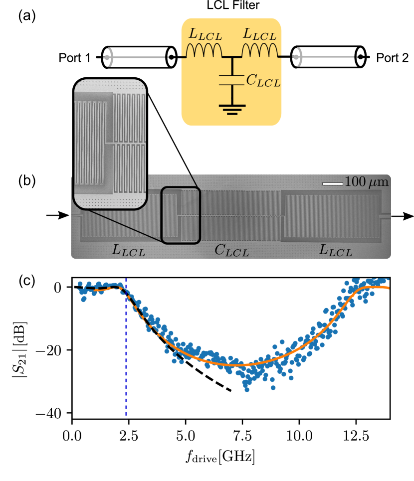
In order to drive the qubit energy cyclically, sinusoidal or arbitrary voltage driving should be applied through the gate line to modulate the qubit energy level between the low-frequency () and high-frequency () resonator, without introducing noise or microwave leakage through the driving line. Quarter-wave () resonators, which have a voltage maximum at the open side, interact capacitively with the gate line, introducing some microwave leakage to the line. Filtering the operating range of the qubit (4-8 GHz) whilst allowing an AC-signal up to few GHz is pivotal. We utilize a superconducting -circuit acting as a lowpass filter Hao et al. (2014), enabling us to prevent microwave leakage with around attenuation and to drive the qubit up to a cutoff frequency of few GHz. Figure 4(a) shows the schematic circuit of an -filter consisting of two series inductors shunted at the center by a capacitor. In the fabricated device, as shown in Fig. 4(b), the filter is realized by a meandering-line inductor () and an interdigitated capacitor () both with a central width and line-spacing of .
To understand the transmission properties, the filter is separately characterized at , as shown in Fig. 4(c), by measuring of a sinusoidal signal with frequency between port 1 and port 2. The blue dots in Fig. 4(c) show the calibrated signal, and exhibit close to transmission up to GHz and dB attenuation within the range of 4-10 GHz. Above 10 GHz, the attenuation starts to decrease and reaches 0 dB at . A lumped circuit model of transmission derived from the ABCD matrix (dashed black line), discussed in detail in App. C, predicts the filter’s behavior up to 4 GHz and deviates above it due to the parasitic capacitance of the meandering inductors, which is not taken into account in the model. From the fitting, the cut off frequency is obtained to be 2.3 GHz with nH and pF. A finite element simulation using SONNET (orange line) captures fully the filter’s transmission with excellent agreement. The characterized filter is capable of blocking microwave leakage within the frequency range of the two resonators, whilst still allowing cyclic driving of the qubit up to 2.3 GHz.
VII Proposed Operation of the Quantum Otto Refrigerator
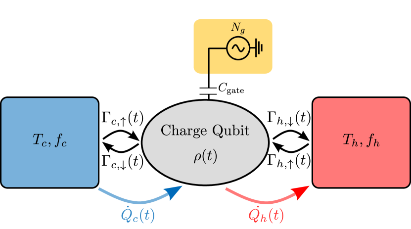
The measured device could be modified to operate as a quantum Otto refrigerator by terminating the two resonators by normal-metal resistors Karimi and Pekola (2016). The resistor-terminated resonators act as a thermal bath Ronzani et al. (2018); Senior et al. (2020). Furthermore, by connecting superconducting probes to the resistors through an insulating barrier the temperature of the two baths could be controlled and monitored through voltage and current bias respectively Giazotto et al. (2006). Due to the dissipation created by the normal-metal probes, the quality factor of the resonators would be very low (Q ) Chang et al. (2019), and qubit spectroscopic characterization could no longer be performed.
The Otto refrigerator cycle is the most practically achievable implementation of a quantum refrigerator. The Otto cycle consists of sequential interactions between a two-level system and a cold () and hot () reservoir. It has four branches: an adiabatic stroke of the qubit frequency from to , thermalization with the hot bath at frequency , an adiabatic stroke back from to , and finally thermalization with the cold bath at frequency . Cooling is achieved under the condition , where , are the temperatures of the normal-metal elements shunting the hot and cold resonators to ground, respectively.
To implement the quantum Otto cycle in our system, we should consider Eq. (2) however allowing time dependence in the offset charge . We consider driving the system with a truncated trapezoidal shape,
| (10) |
where is a constant, a form previously demonstrated to yield a large cooling power Karimi and Pekola (2016). The offset charge is applied by gate voltage, and driven in the form
| (11) |
in which and are the offset charge at which the qubit interacts with the cold and hot reservoir respectively, obtained from rearranging Eq. (3).
For a qubit coupled to a resonator its emission rates are altered according to the Purcell effect, and can be calculated using Fermi’s golden rule Koch et al. (2007). Following Karimi and Pekola (2016); Funo et al. (2019) we consider the dissipators to take the form of Johnson-Nyquist noise generated by a normal metal resistor, and spectrally filtered by the Lorentzian function of the resonators. The transition rates are therefore described by
| (12) |
where is the resonator frequency, is the associated quality factor, is the instantaneous qubit frequency, and is the temperature of each normal-metal resistor terminating the resonator. The rates coming from the two heat baths obey the detailed balance condition as
| (13) |
In this way, the transition rates from each bath are maximized when the qubit is in resonance with the corresponding resonator frequency. Due to the finite quality factor of the resonators, this protocol can only approximate the Otto cycle since the qubit is never fully decoupled from either bath. Furthermore, the cooling power at the highest drive frequencies is limited by these transition rates, since the cycle becomes too short for the qubit to reach equilibrium with the resonators.
In limit where the bath-resonator coupling exceeds the resonator qubit coupling (local limit), and in the limit of slow driving, the evolution of the qubit density matrix can be described by a Lindblad master equation as Lindblad (1976)
| (14) | ||||
where are the qubit transition rates, are the instantaneous jump operators of the system and defines the anti-commutator operation.
The equivalent heat flow diagram, including two heat baths and the corresponding rates, is shown in Fig. 5. We simplify Eq. (14) by transforming to the rotating frame using Menczel et al. (2019), where is the unitary matrix diagonalizing . Then, parameterizing in terms of the Bloch equation elements, , , , the evolution results in the compact expressions
| (15) | |||
| (16) | |||
| (17) |
Based on this, we further note that the condition for adiabatic evolution in our system is Schaller et al. (2006)
| (18) |
where fulfilment means that the system remains in an instantaneous eigenstate throughout the evolution. Furthermore, we can write the exact heat currents from each bath in terms of the elements of the Bloch vector as
| (19) |
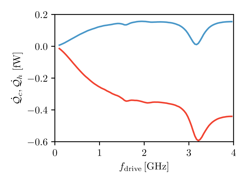
Figure 6 shows the average power extracted from the hot and cold baths as the red and blue solid lines for the measured system parameters, averaged over one cycle one the system has reached the steady state. Furthermore, it can be seen that the rate of entropy production is consistent according to the second law .
Interestingly, the driving rate in our system could be high enough to observe quantum behavior in the refrigerator cooling power, whereby off-diagonal terms in the density matrix, , could begin to affect the refrigerator performance. In the simulations, the quantum effects are clearly visible by sharp oscillations in the cooling power at high values of , as has been seen in previous theoretical studies involving qubit Otto refrigerators Karimi and Pekola (2016). Dips are created when the frequency of the free qubit rotation about the Bloch sphere matches the driving frequency. In the future, to suppress this behavior, a counter-diabatic driving protocol could be implemented, which generally consists of an additional field to ‘guide’ the qubit along an adiabatic trajectory Funo et al. (2019). We note however, that for very fast driving the Lindblad operators may no longer be jump operators between the instantaneous eigenstates of the Hamiltonian. The modeling could be further improved by utilizing more advanced Floquet master equations, as was done in Gelbwaser-Klimovsky et al. (2013), for example.
In addition to the direct heat-flows discussed here, tunneling quasiparticles in the system will also affect the refrigerator performance. We see experimental evidences of this effect from the non-interacting portion of the signal seen in Fig. 2(a) and Fig. 2(b). Since each tunnelling quasiparticle shifts the qubit transition off-resonance, we can understand this effect as a reduction in the effective coupling strength to each resonator, i.e. and . Incorporating such an effect into the numerics reduces the peak cooling power from to , still detectable using standard normal metal-insulator-superconductor (NIS) thermometry techniques. However, this highlights the importance of further quasiparticle mitigation strategies.
VIII Conclusion
In summary, a charge sensitive qubit has been coupled to two superconducting coplanar waveguides for the first time, with the ability to drive the qubit over a large frequency range using remarkably small excitations. Additionally, the measured effective coupling strength of the qubit to each resonator remains exceptionally high, competitive with the highest previously measured in charge sensitive devices. Furthermore, we demonstrate that despite the close proximity of the various coupling elements, our system can be simply described within the framework of a two-level qubit interacting with two resonators. Utilizing the measured device parameters, we propose and simulate the operation of our device acting as a quantum Otto refrigerator, and show cooling powers of the order which is detectable using normal metal-insulator-normal metal (NIS) thermometry. Additionally, the measured system could be used to realize a highly effective heat rectifier, owing to the large anharmonicity of the charge qubit, allowing the isolation of a single qubit transition. Our work lays the technical foundation towards the realization of cyclic quantum heat engines within the c-QED framework, and opens the door towards a multitude of future studies in the field of quantum thermodynamics.
Appendix A Fabrication Details
The fabrication of the device is done in a multistage process on a -thick and highly resistive silicon substrate. The fabrication consists of two main steps: patterning microwave structures on a Nb film, and Josephson-junction elements on an Al film. A -thick Al2O3 layer is deposited onto a silicon substrate using atomic layer deposition, followed by a deposition of a -thick Nb film using DC magnetron sputtering. Positive electron beam resist, AR-P6200.13, is spin-coated with a speed of 5500 rpm for 60 s, and is post-baked for 9 minutes at 150∘C, which is then patterned by electron beam lithography (EBL) and etched by reactive ion etching. A shadow mask defined by EBL on a 1 -thick poly(methyl-metacrylate)/copolymer resist bilayer is used to fabricate the Al island and Josephson junction using a two-angle deposition technique at 0∘ and 32∘ sequentially. Before the deposition, the Nb surface is cleaned in-situ by Ar ion plasma milling for 45 s, followed by first 8 nm-thick Al island deposition. The island then is oxidized at pressure 2.5 mbar for 2.5 minutes to form a tunnel barrier before depositing the second 100 nm Al film. Finally, after liftoff in acetone and isopropyl alcohol, the substrate is cut by an automatic dicing-saw machine to the size mm and wire-bonded to an RF-holder for the low-temperature characterization.
Appendix B Experimental Details
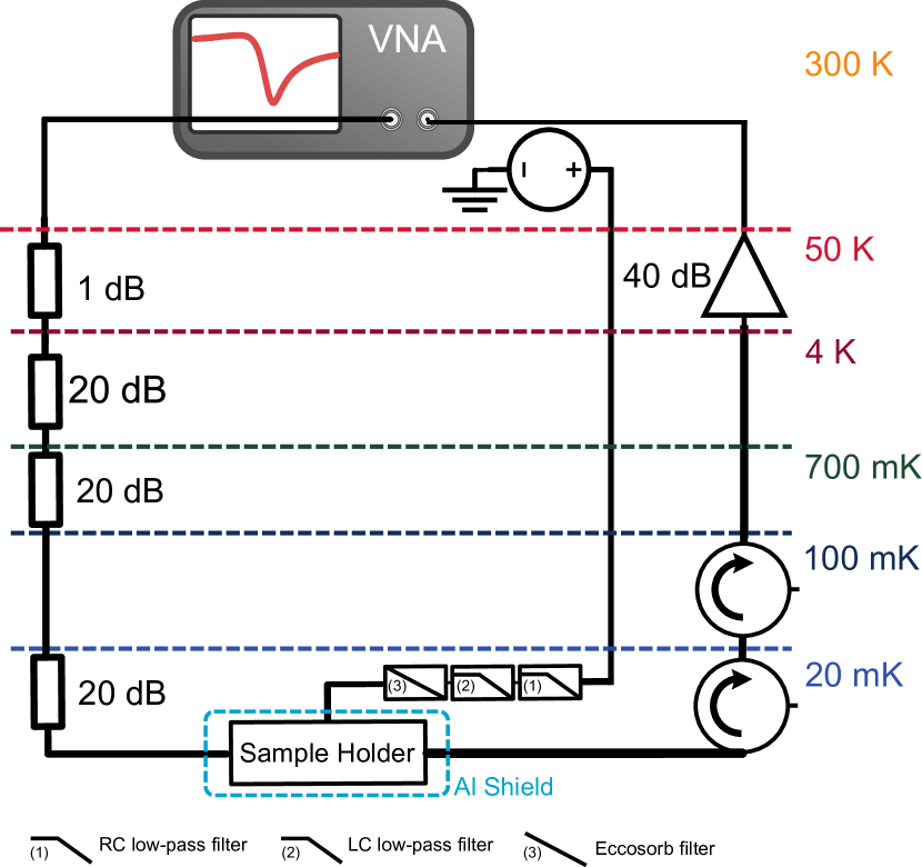
Measurements are performed in a cryogen-free dilution refrigerator with a base temperature of . Using a VNA, a probe microwave tone is supplied to the feedline through a of attenuation distributed at the various temperature stages of the cryostat. The probe signal is then passed through two cryogenic circulators, before being amplified first by a cryogenic amplifier, and secondly by a room-temperature amplifier. The offset charge, , is supplied by a nearby voltage gate, with DC component passed though an low temperature filter, filter, and eccoscorb filter, and connected to an isolated voltage source at room temperature. The device is mounted in a tight cooper holder and covered by an Al-shield to protect from stray magnetic field and incident radiation.
Appendix C -Filter Transmission
The transmission matrix, or ABCD matrix, of a network is constructed by multiplying the ABCD matrices of each individual two-port element sequentially Pozar (2005). In the case of network, the ABCD matrix is given by the multiplication of ABCD matrices of the inductor () in series, capacitor () in parallel and inductor () in series, as schematically shown in Fig. 4(a) and formulated as follows
| (20) |
The voltage ratio between port 2 and port 1 (), can then be calculated as
| (21) |
| (22) |
where , , and ; and are inductance and capacitance values of the -filter.
Acknowledgments
We acknowledge Dr. Joonas Peltonen, Dr. Dmitry Golubev, Dr. George Thomas, Dr. Neill Lambert and Ilari Mäkinen for technical support and insightful discussions. This work is financially supported through the Foundational Questions Institute Fund (FQXi) via Grant No. FQXi-IAF19-06, Academy of Finland grants 312057, the Russian Science Foundation (Grant No. 20-62-46026) and from the European Union’s Horizon 2020 research and innovation programme under the European Research Council (ERC) (Grant No. 742559). We acknowledge the provision of facilities by Micronova Nanofabrication Centre and OtaNano - Low Temperature Laboratory of Aalto University to perform this research. We thank VTT Technical Research Center for sputtered Nb films.
Data Availability Statement
All data used in this paper are available upon request to the authors, including descriptions of the data sets, and scripts to generate the figures.
References
- Kosloff and Levy (2014) R. Kosloff and A. Levy, “Quantum heat engines and refrigerators: Continuous devices,” Annu. Rev. Phys. Chem. 65, 365–393 (2014).
- Alicki (1979) R. Alicki, “The quantum open system as a model of the heat engine,” J. Phys. A: Math. Gen. 12, L103–L107 (1979).
- Quan et al. (2007) H. T. Quan, Yu-xi. Liu, C. P. Sun, and F. Nori, “Quantum thermodynamic cycles and quantum heat engines,” Phys. Rev. E 76, 031105 (2007).
- Binder et al. (2019) F. Binder, L. A. Correa, C. Gogolin, J. Anders, and G. Adesso, Thermodynamics in the Quantum Regime (Springer-Verlag GmbH, 2019).
- Kosloff (2013) R. Kosloff, “Quantum thermodynamics: A dynamical viewpoint,” Entropy 15, 2100–2128 (2013).
- Karimi and Pekola (2016) B. Karimi and J. P. Pekola, “Otto refrigerator based on a superconducting qubit: Classical and quantum performance,” Phys. Rev. B 94, 184503 (2016).
- Niskanen et al. (2007) A. O. Niskanen, Y. Nakamura, and J. P. Pekola, “Information entropic superconducting microcooler,” Phys. Rev. B 76, 174523 (2007).
- Roßnagel et al. (2016) J. Roßnagel, S. T. Dawkins, K. N. Tolazzi, O. Abah, E. Lutz, F. Schmidt-Kaler, and K. Singer, “A single-atom heat engine,” Science 352, 325–329 (2016).
- Josefsson et al. (2018) M. Josefsson, A. Svilans, A. M. Burke, E. A. Hoffmann, S. Fahlvik, C. Thelander, M. Leijnse, and H. Linke, “A quantum-dot heat engine operating close to the thermodynamic efficiency limits,” Nat. Nanotechnol. 13, 920–924 (2018).
- Peterson et al. (2019) J. P. S. Peterson, T. B. Batalhão, M. Herrera, A. M. Souza, R. S. Sarthour, I. S. Oliveira, and R. M. Serra, “Experimental characterization of a spin quantum heat engine,” Phys. Rev. Lett. 123, 240601 (2019).
- Ono et al. (2020) K. Ono, S. N. Shevchenko, T. Mori, S. Moriyama, and F. Nori, “Analog of a quantum heat engine using a single-spin qubit,” Phys. Rev. Lett. 125, 166802 (2020).
- You and Nori (2005) J. Q. You and F. Nori, “Superconducting circuits and quantum information,” Phys. Today 58, 42–47 (2005).
- Gu et al. (2017) X. Gu, A. F. Kockum, A. Miranowicz, Y.-x. Liu, and F. Nori, “Microwave photonics with superconducting quantum circuits,” Phys. Rep. 718-719, 1–102 (2017).
- Kjaergaard et al. (2020) M. Kjaergaard, M. E. Schwartz, J. Braumüller, P. Krantz, J. I.-J. Wang, S. Gustavsson, and W. D. Oliver, “Superconducting qubits: Current state of play,” Annu. Rev. Condens. Matter Phys. 11, 369–395 (2020).
- Wallraff et al. (2004) A. Wallraff, D. I. Schuster, A. Blais, L. Frunzio, R.-S. Huang, J. Majer, S. Kumar, S. M. Girvin, and R. J. Schoelkopf, “Strong coupling of a single photon to a superconducting qubit using circuit quantum electrodynamics,” Nature 431, 162–167 (2004).
- Blais et al. (2004) A. Blais, R.-S. Huang, A. Wallraff, S. M. Girvin, and R. J. Schoelkopf, “Cavity quantum electrodynamics for superconducting electrical circuits: An architecture for quantum computation,” Phys. Rev. A 69, 062320 (2004).
- Schuster et al. (2007) D. I. Schuster, A. A. Houck, J. A. Schreier, A. Wallraff, J. M. Gambetta, A. Blais, L. Frunzio, J. Majer, B. Johnson, M. H. Devoret, S. M. Girvin, and R. J. Schoelkopf, “Resolving photon number states in a superconducting circuit,” Nature 445, 515–518 (2007).
- Clarke and Wilhelm (2008) J. Clarke and F. K. Wilhelm, “Superconducting quantum bits,” Nature 453, 1031–1042 (2008).
- Montanaro (2016) A. Montanaro, “Quantum algorithms: an overview,” npj Quantum Inf. 2, 15023 (2016).
- Wendin (2017) G. Wendin, “Quantum information processing with superconducting circuits: a review,” Rep. Prog. Phys. 80, 106001 (2017).
- Chang et al. (2019) Y.-C. Chang, B. Karimi, J. Senior, A. Ronzani, J. T. Peltonen, H.-S. Goan, C.-D. Chen, and J. P. Pekola, “Utilization of the superconducting transition for characterizing low-quality-factor superconducting resonators,” Appl. Phys. Lett. 115, 022601 (2019).
- Giazotto et al. (2006) F. Giazotto, T. T. Heikkilä, A. Luukanen, A. M. Savin, and J. P. Pekola, “Opportunities for mesoscopics in thermometry and refrigeration: Physics and applications,” Rev. Mod. Phys. 78, 217–274 (2006).
- Pekola and Karimi (2021) J. P. Pekola and B. Karimi, “Colloquium: Quantum heat transport in condensed matter systems,” Rev. Mod. Phys. 93, 041001 (2021).
- Ronzani et al. (2018) A. Ronzani, B. Karimi, J. Senior, Y.-C. Chang, J. T. Peltonen, C. Chen, and J. P. Pekola, “Tunable photonic heat transport in a quantum heat valve,” Nat. Phys. 14, 991–995 (2018).
- Senior et al. (2020) J. Senior, A. Gubaydullin, B. Karimi, J. T. Peltonen, J. Ankerhold, and J. P. Pekola, “Heat rectification via a superconducting artificial atom,” Communications Physics 3, 40 (2020).
- Camati et al. (2019) P. A. Camati, J. F. G. Santos, and R. M. Serra, “Coherence effects in the performance of the quantum Otto heat engine,” Phys. Rev. A 99, 062103 (2019).
- Insinga (2020) A. R. Insinga, “The quantum friction and optimal finite-time performance of the quantum Otto cycle,” Entropy 22 (2020).
- Kloc et al. (2021) M. Kloc, K. Meier, K. Hadjikyriakos, and G. Schaller, “Superradiant many-qubit absorption refrigerator,” Phys. Rev. Applied 16, 044061 (2021).
- Abah and Lutz (2016) O. Abah and E. Lutz, “Optimal performance of a quantum Otto refrigerator,” EPL (Europhysics Letters) 113, 60002 (2016).
- Brandner and Seifert (2016) K. Brandner and U. Seifert, “Periodic thermodynamics of open quantum systems,” Phys. Rev. E 93, 062134 (2016).
- Pekola et al. (2019) J. P. Pekola, B. Karimi, G. Thomas, and D. V. Averin, “Supremacy of incoherent sudden cycles,” Phys. Rev. B 100, 085405 (2019).
- Hofer et al. (2016) P. P. Hofer, J.-R. Souquet, and A. A. Clerk, “Quantum heat engine based on photon-assisted Cooper pair tunneling,” Phys. Rev. B 93, 041418 (2016).
- Campisi and Fazio (2016) M. Campisi and R. Fazio, “The power of a critical heat engine,” Nat. Commun. 7, 11895 (2016).
- Solfanelli et al. (2020) A. Solfanelli, M. Falsetti, and M. Campisi, “Nonadiabatic single-qubit quantum Otto engine,” Phys. Rev. B 101, 054513 (2020).
- Kieu (2004) T. D. Kieu, “The second law, maxwell’s demon, and work derivable from quantum heat engines,” Phys. Rev. Lett. 93, 140403 (2004).
- Gelbwaser-Klimovsky et al. (2013) D. Gelbwaser-Klimovsky, R. Alicki, and G. Kurizki, “Minimal universal quantum heat machine,” Phys. Rev. E 87, 012140 (2013).
- Nazarov and Blanter (2009) Y. V. Nazarov and Y. M. Blanter, Quantum Transport: Introduction to Nanoscience (Cambridge University Press, Cambridge, 2009).
- Nakamura et al. (1999) Y. Nakamura, Yu. A. Pashkin, and J. S. Tsai, “Coherent control of macroscopic quantum states in a single-Cooper-pair box,” Nature 398, 786–788 (1999).
- Pashkin et al. (2009) Yu. A. Pashkin, O. Astafiev, T. Yamamoto, Y. Nakamura, and J. S. Tsai, “Josephson charge qubits: a brief review,” Quantum Inf. Process. 8, 55–80 (2009).
- Bladh et al. (2005) K. Bladh, T. Duty, D. Gunnarsson, and P. Delsing, “The single Cooper-pair box as a charge qubit,” New J. Phys. 7, 180–180 (2005).
- Sillanpää et al. (2006) M. Sillanpää, T. Lehtinen, A. Paila, Y. Makhlin, and P. Hakonen, “Continuous-time monitoring of landau-zener interference in a Cooper-pair box,” Phys. Rev. Lett. 96, 187002 (2006).
- Astafiev et al. (2007) O. Astafiev, K. Inomata, A. O. Niskanen, T. Yamamoto, Yu. A. Pashkin, Y. Nakamura, and J. S. Tsai, “Single artificial-atom lasing,” Nature 449, 588–590 (2007).
- Kim et al. (2008) Z. Kim, V. Zaretskey, Y. Yoon, J. F. Schneiderman, M. D. Shaw, P. M. Echternach, F. C. Wellstood, and B. S. Palmer, “Anomalous avoided level crossings in a Cooper-pair box spectrum,” Phys. Rev. B 78, 144506 (2008).
- Kim et al. (2011) Z. Kim, B. Suri, V. Zaretskey, S. Novikov, K. D. Osborn, A. Mizel, F. C. Wellstood, and B. S. Palmer, “Decoupling a Cooper-pair box to enhance the lifetime to 0.2 ms,” Phys. Rev. Lett. 106, 120501 (2011).
- Maillet et al. (2020) O. Maillet, D. Subero, J. T. Peltonen, D. S. Golubev, and J. P. Pekola, “Electric field control of radiative heat transfer in a superconducting circuit,” Nat. Commun. 11, 4326 (2020).
- Koch et al. (2007) J. Koch, T. M. Yu, J. Gambetta, A. A. Houck, D. I. Schuster, J. Majer, A. Blais, M. H. Devoret, S. M. Girvin, and R. J. Schoelkopf, “Charge-insensitive qubit design derived from the Cooper pair box,” Phys. Rev. A 76, 042319 (2007).
- Stassi et al. (2020) R. Stassi, M. Cirio, and F. Nori, “Scalable quantum computer with superconducting circuits in the ultrastrong coupling regime,” npj Quantum Inf. 6, 67 (2020).
- Lindblad (1976) G. Lindblad, “On the generators of quantum dynamical semigroups,” Communications in Mathematical Physics 48, 119–130 (1976).
- Heinz-Peter Breuer (2007) F. P. Heinz-Peter Breuer, The Theory of Open Quantum Systems (Oxford University Press, 2007).
- Groszkowski and Koch (2021) P. Groszkowski and J. Koch, “Scqubits: a python package for superconducting qubits,” (2021), arXiv:2107.08552 .
- Probst et al. (2015) S. Probst, F. B. Song, P. A. Bushev, A. V. Ustinov, and M. Weides, “Efficient and robust analysis of complex scattering data under noise in microwave resonators,” Rev. Sci. Instrum. 86, 024706 (2015).
- Yamamoto et al. (2006) T. Yamamoto, Y. Nakamura, Yu. A. Pashkin, O. Astafiev, and J. S. Tsai, “Parity effect in superconducting aluminum single electron transistors with spatial gap profile controlled by film thickness,” Appl. Phys. Lett. 88, 212509 (2006).
- Aumentado et al. (2004) J. Aumentado, M. W. Keller, J. M. Martinis, and M. H. Devoret, “Nonequilibrium quasiparticles and periodicity in single-Cooper-pair transistors,” Phys. Rev. Lett. 92, 066802 (2004).
- Sun et al. (2012) L. Sun, L. DiCarlo, M. D. Reed, G. Catelani, L. S. Bishop, D. I. Schuster, B. R. Johnson, G. A. Yang, L. Frunzio, L. Glazman, M. H. Devoret, and R. J. Schoelkopf, “Measurements of quasiparticle tunneling dynamics in a band-gap-engineered transmon qubit,” Phys. Rev. Lett. 108, 230509 (2012).
- Serniak et al. (2019) K. Serniak, S. Diamond, M. Hays, V. Fatemi, S. Shankar, L. Frunzio, R. Schoelkopf, and M. Devoret, “Direct dispersive monitoring of charge parity in offset-charge-sensitive transmons,” Phys. Rev. Applied 12, 014052 (2019).
- Catelani and Pekola (2022) G. Catelani and J. P. Pekola, “Using materials for quasiparticle engineering,” Materials for Quantum Technology 2, 013001 (2022).
- Schuster et al. (2005) D. I. Schuster, A. Wallraff, A. Blais, L. Frunzio, R.-S. Huang, J. Majer, S. M. Girvin, and R. J. Schoelkopf, “AC stark shift and dephasing of a superconducting qubit strongly coupled to a cavity field,” Phys. Rev. Lett. 94, 123602 (2005).
- Astafiev et al. (2004) O. Astafiev, Yu. A. Pashkin, Y. Nakamura, T. Yamamoto, and J. S. Tsai, “Quantum noise in the Josephson Charge qubit,” Phys. Rev. Lett. 93, 267007 (2004).
- Hao et al. (2014) Y. Hao, F. Rouxinol, and M. D. LaHaye, “Development of a broadband reflective T-filter for voltage biasing high-Q superconducting microwave cavities,” Appl. Phys. Lett. 105, 222603 (2014).
- Funo et al. (2019) K. Funo, N. Lambert, B. Karimi, J. P. Pekola, Y. Masuyama, and F. Nori, “Speeding up a quantum refrigerator via counterdiabatic driving,” Phys. Rev. B 100, 035407 (2019).
- Menczel et al. (2019) P. Menczel, T. Pyhäranta, C. Flindt, and K. Brandner, “Two-stroke optimization scheme for mesoscopic refrigerators,” Phys. Rev. B 99, 224306 (2019).
- Schaller et al. (2006) G. Schaller, S. Mostame, and R. Schützhold, “General error estimate for adiabatic quantum computing,” Phys. Rev. A 73, 062307 (2006).
- Pozar (2005) D. M. Pozar, Microwave engineering; 3rd ed. (Wiley, Hoboken, NJ, 2005).