The limits of multiplexing quantum and classical channels: Case study of a 2.5 GHz discrete variable quantum key distribution system
Abstract
Network integration of quantum key distribution is crucial for its future widespread deployment due to the high cost of using optical fibers dedicated for the quantum channel, only. We studied the performance of a system running a simplified BB84 protocol at repetition rate, operating in the original wavelength band, short O-band, when multiplexed with communication channels in the conventional wavelength band, short C-band. Our system could successfully generate secret keys over a single-mode fiber with a length of and with co-propagating classical signals at a launch power of . Further, we discuss the performance of an ideal system under the same conditions, showing the limits of what is possible with a discrete variable system in the O-band. We also considered a short and lossy link with optical fiber resembling a real link in a metropolitan area network. In this scenario we could exchange a secret key with a launch power up to in the classical channels.
Quantum key distribution (QKD) allows for distribution of secret keys between distant parties. As of today, a variety of QKD experiments have shown the feasibility of exchanging keys through a dedicated optical fiber over hundreds of kilometers Boaron et al. (2018); Chen et al. (2020); Pittaluga et al. (2020). However, the deployment and maintenance of optical fiber reserved for QKD only is rather costly and would hence limit the use cases of QKD. Therefore a pressing issue is the seamless integration of QKD into the already existing optical fiber network infrastructure. Using wavelength division multiplexing (WDM), it is possible to couple both QKD and classical communication signals to the same fiber Townsend (1997). The challenge of this approach lies in the fact that QKD protocols typically require a launch power of less than , whereas classical signals are launched with a power in the order of per channel. A small fraction of the classical signal arriving at the QKD receiver is enough to increase the quantum bit error rate (QBER) to a value where key extraction is impossible.
In many network environments, the classical signals populate the conventional wavelength band (C-band) from to separated by in a dense WDM (DWDM) grid. Upon coexisting with a quantum channel, a classical signal generates noise at the quantum receiver due to imperfect isolation between the DWDM channels or via non-linear processes. Raman scattering and, depending on the choice of the DWDM channels and the quantum channel wavelength, four-wave mixing are the dominant non-linear processes Eraerds et al. (2010); Aleksic et al. (2015); Tkach et al. (1995). While the channel isolation can be easily increased by adding suitable filters, non-linear processes can create photons at the same wavelength as the quantum signal which cannot be spectrally filtered. Four-wave mixing is restricted to narrow spectral regions and can therefore be avoided by choosing the quantum wavelength carefully. Raman noise, on the other hand, exhibits a broad spectrum. For example, classical signals in one C-band channel create a Raman noise spectrum covering the whole C-band with only two narrow local minima close to the pump wavelength Eraerds et al. (2010). In a densely populated WDM environment, the local minima are covered by the Raman noise of other channels.
One can make use of temporal filtering to help reduce the impact of noise photons at the quantum channel wavelength Patel et al. (2012); Mao et al. (2018). The propagation direction of the classical signals also have an influence on the amount of introduced noise. A signal counter-propagating to the quantum signal introduces more Raman noise than a co-propagating one due to the isotropic nature of Raman scattering and the higher power in vicinity to the receiver Eraerds et al. (2010).
Regarding the quantum channel wavelength, there are two frequent choices. Either it is placed in the C-band or in the original wavelength band (O-band) from to . The advantage of placing it in the C-band is the high fiber transmission. However, in a network, the quantum channel is then spectrally close to the classical channels and therefore strongly affected by Raman noise. Placing the quantum channel in the O-band reduces the amount of Raman noise but also the fiber transmission Townsend (1997); Wang et al. (2017); Aleksic et al. (2015). Generally speaking, it is advantageous to put the quantum signal in the O-band above a certain power threshold for the classical channels in the C-band Wang et al. (2017). In present-day networks, the total loss of a link is often dominated by the excess loss due to fiber connections, routing devices or other components. In such an environment, a quantum channel in the O-band is advantageous since the transmission approaches the one of the C-band, but the noise is reduced. For both choices of quantum channel wavelength, the performance of QKD systems in the presence of classical communication has been studied Townsend (1997); Mao et al. (2018); Fröhlich et al. (2017); Kumar et al. (2015); Milovancev et al. (2021); Geng et al. (2021). One study also considered a quantum channel in the long wavelength band (L-band) from to and the short wavelength band (S-band) from to Kleis et al. (2019).
The performance of a QKD system in a network depends heavily on the quality of the noise filtering on the receiver side. First, high isolation of the quantum channel from the classical channel is needed. This can be easily achieved by cascading WDM modules. Second, high Raman noise rejection is desired. The quality of noise rejection depends on the time-bandwidth product of the quantum signal and on how tight the temporal and spectral filtering can be implemented. In the case of continuous variable (CV-)QKD systems, the homodyne detection acts as a spectral filter Qi et al. (2010). For discrete variable (DV-)QKD systems, like the one presented in this study, filters have to be added at a cost of decreasing the transmission.
In this work we demonstrate the operation of a QKD system with a quantum channel in the O-band with a wavelength of . We consider a scenario where all the classical signals are co-propagating in the same fiber. This configuration is often found in metropolitan networks Ciurana et al. (2014); Aleksic et al. (2015). The quantum channel is launched in the same direction as the classical channels to minimize the degradation of the quantum signal. We consider a channel where the loss is only given by the fiber attenuation and another channel where a substantial amount of loss is given by imperfections, which is a more realistic model for a network environment. Finally, we compare our setup to an ideal system in terms of temporal and spectral filtering.
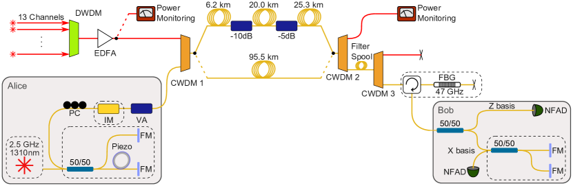
We utilize a simple time-bin protocol with one decoy state, operating at a qubit repetition rate of Boaron et al. (2016). The QKD implementation and the configuration of the classical channels are depicted in Figure 1. Alice encodes the qubits in two time-bins. The bits in the Z basis, which are used to generate the key, are encoded in either the early or late time bin. Only one state in the X basis is used, namely the superposition of the the early and late bin with a fixed relative phase. The laser source is a gain-switched distributed feedback laser emitting pulses with a full width at half maximum (FWHM) of . Due to the gain-switching the pulses are chirped.
Bob uses free-running InGaAs/InP negative-feedback avalanche diodes (NFADs) Amri et al. (2016). Both NFADs are cooled to , show a detection efficiency of 25% at and a jitter of . The detector in the X basis (Z basis) shows a dark count rate of ().
The dead time was set to for the detector in the X basis and to for the one in the Z basis. The detection window per time bin has a duration of . Detections outside this window are ignored by the acquisition system. The error correction was performed with a Cascade algorithm Martinez-Mateo et al. (2015), with an efficiency of 1.05. The compression factor was calculated over a privacy amplification block of bits and taking into account finite-key effects Rusca et al. (2018).
The classical communication runs over thirteen C-band channels. They are multiplexed with a DWDM module and then amplified using an erbium-doped fiber amplifier. The quantum channel is added to the fiber with a coarse WDM (CWDM) module. On the receiver end, the quantum and classical signals are separated by a CWDM module. Another CWDM module is used to increase isolation between quantum and classical channels. To prevent classical signals to travel multiple times between the CWDM modules and to further improve the isolation, we added a fiber spool with a winding radius of and 36 windings. This spool has an insertion loss of at and at . The remaining signal and noise are filtered by a fiber Bragg grating (FBG) with a transmission window of FWHM and more than of extinction outside the window.
| Description | Insertion loss at (dB) | Isolation from (dB) | Remarks |
|---|---|---|---|
| CWDM 1 | 0.8 | ||
| CWDM 2 | 0.6 | ||
| CWDM 3 | 0.8 | ||
| Filter Spool | 1.0 | 32.9 | |
| Fiber Bragg grating (FBG) and circulator | 4.0 | The insertion loss is partially caused by spectral mismatch of laser pulse and filter. A loss of was measured at peak transmission. | |
| Loss due to detector jitter and pulse broadening by FBG | 1.9 | - | The loss was obtained by observing the ratio between detection events outside and inside the detection time window. |
The excess loss experienced by the quantum signal due to the filters is summarized in Table 1. The spectral width of the laser is close to the spectral width of the FBG, leading to increased insertion loss. Further, the FBG is slightly chirped and therefore the already chirped laser pulse gets temporally broadened by the FBG. The broadening due to the FBG together with the detector jitter increases the chance to detect the pulse outside the predefined time window, and therefore effectively introduces loss.
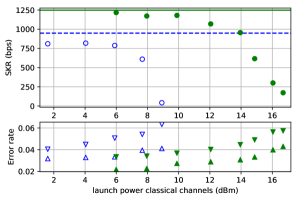
We performed secret key exchanges in two different regimes. First, we considered a case similar to a real network where we used standard single mode fiber (Corning® SMF-28e+®) with a length of together with of excess loss in the channel (see Figure 1 for details). This configuration acts as a model for a realistic link. In a metropolitan network, this loss could be due to connectors and routing equipment. Second, we exchanged a key over of standard single-mode fiber (Corning® SMF-28e+®). This measurement was done for ease of comparison with previous studies. In both cases we are interested in the secret key rate as a function of the launch power in the classical channels.
In Figure 2 we show the secret key rate, the QBER in the Z basis and the phase error rate as a function of the classical launch power for the two different channel configurations. We obtained a secret key rate of with a launch power of , which corresponds to a total received power of . In the case of the long and high loss link, a secret key rate of could be obtained at total launch power of , corresponding to a total received power of .
We were also interested in finding the limits of what would be possible with an ideal setup using the same protocol, quantum channel wavelength and repetition rate as our experiment. For this we assume that the filter block on Bob’s side (CWDM 3, filter spool, circulator and FBG in Figure 1) has negligible insertion loss, that the detectors have no jitter and no dark counts, that Alice is sending Fourier-limited -pulses and that the filter spectrum of the FBG would be optimized both in bandwidth and in shape for these pulses. Our simulation shows that in this case, the maximum tolerable launch power would increase by , where could be gained due to the absence of jitter, the optimized shape and bandwidth of the FBG and of the laser pulse and could be gained if we had an ideal filter block with negligible insertion loss. We also estimated that we the maximum tolerable launch power would increase by if we used superconducting nanowire single-photon detectors (SNSPDs) with a jitter of instead of NFADs with a jitter of as in our experimental setup.
| continuous/discrete variable QKD | Wavelength band | fiber length () | att. quantum channel () | launch power () | secret key rate (bps) | finite-key statistics | Ref. |
|---|---|---|---|---|---|---|---|
| discrete | O | 51.5 | 34.1 | 16.7 | Yes | This work | |
| 51.5 | 34.1 | 13.9 | |||||
| 95.5 | 34.8 | 5.9 | |||||
| 95.5 | 34.8 | 8.9 | |||||
| 66.0 | 22.3 | 21.0 | Yes | Mao et al. (2018) | |||
| 66.0 | 22.3 | 16.0 | |||||
| 66.0 | 22.3 | 11.0 | |||||
| 40.0 | 12.8∗ | 17.6 | No | Geng et al. (2021) | |||
| 50.0 | 16.0∗ | 14.7 | |||||
| 60.0 | 19.2∗ | 11.7 | |||||
| 60.0 | 19.2∗ | 4.0 | Yes | Wang et al. (2017) | |||
| 80.0 | 25.6∗ | 4.0 | |||||
| C | 50.0 | 9.6 | -18.5 | Yes | Dynes et al. (2016) | ||
| 50.0 | 9.6 | -12.5 | |||||
| 50.0 | 9.6 | -5.5 | |||||
| 100.0 | 18.0∗ | -3.1 | Yes | Fröhlich et al. (2017) | |||
| 150.0 | 27.0∗ | -8.1 | |||||
| 150.0 | 27.0∗ | -5.0 | |||||
| continuous | C | 25.0 | 5.0∗ | 11.5 | Yes | Kumar et al. (2015) | |
| 75.0 | 15.0∗ | -0.5 | |||||
| 75.0 | 15.0∗ | -3.0 | |||||
| 13.2 | 3.0∗ | 15.6 | No | Milovancev et al. (2021) | |||
| 28.4 | 6.4∗ | 15.6 | |||||
| S | 25.0 | 5.0∗ | 14.0 | No | Kleis et al. (2019) | ||
| 50.0 | 10.0∗ | 6.0 |
In Figure 3 and Table 2, we compare our work to previous studies. In summary, CV-QKD systems show the best performance both in the tolerated launch power and in the secret key rate at short and low loss links. At longer distances DV-QKD systems, both in the C- and O-band, outperform the CV-QKD systems. We can conclude that, as of today, DV-QKD systems operating in the O-band are best suited for networks with distances between and and high launch power. Furthermore, our results in Figure 2 with the short and high loss link show that in a real network, O-band DV-QKD systems can tolerate more power than suggested by measurements with links where the loss is mainly given by the fiber. Another advantage of O-band QKD systems is that separating a signal from the C-band is possible with rather low loss and high isolation by using CWDM modules. In our case one CWDM module has an insertion loss of and a channel isolation of more than . If we wanted to isolate one C-band channel from other C-band channels we would need DWDM modules, which typically exhibit an insertion loss of while having a channel isolation of only . Therefore it is best to use O-band QKD systems in metropolitan area networks.
In conclusion, we showed that with a simple and practical QKD system it is possible to exchange a secret key in presence of classical channels. We demonstrated the feasibility of key generation for a short distance and high loss link and also for a medium range link where the loss is predominantly given by the fiber attenuation. An ideal DV-QKD system at a repetition rate of in the O-band could tolerate a total launch power of of co-propagating classical signals over of single-mode fiber. This would be even enough to operate the QKD system in a backbone fiber network Mao et al. (2018). Finding ways to prepare almost ideal pulses and manufacturing optimized filters could increase noise tolerance of DV-QKD systems by more than an order of magnitude according to our simulation.
We thank Romain Alléaume and Eleni Diamanti for the useful discussions and the Swiss NCCR QSIT for financial support.
The following article has been accepted by Applied Physics Letters. After it is published, it will be found at https://doi.org/10.1063/5.0060232.
Data availability
The data that support the findings of this study are available from the corresponding author upon reasonable request.
References
- Boaron et al. (2018) A. Boaron, G. Boso, D. Rusca, C. Vulliez, C. Autebert, M. Caloz, M. Perrenoud, G. Gras, F. Bussières, M.-J. Li, D. Nolan, A. Martin, and H. Zbinden, Physical Review Letters 121 (2018), 10.1103/physrevlett.121.190502.
- Chen et al. (2020) J.-P. Chen, C. Zhang, Y. Liu, C. Jiang, W. Zhang, X.-L. Hu, J.-Y. Guan, Z.-W. Yu, H. Xu, J. Lin, M.-J. Li, H. Chen, H. Li, L. You, Z. Wang, X.-B. Wang, Q. Zhang, and J.-W. Pan, Physical Review Letters 124 (2020), 10.1103/physrevlett.124.070501.
- Pittaluga et al. (2020) M. Pittaluga, M. Minder, M. Lucamarini, M. Sanzaro, R. I. Woodward, M.-J. Li, Z. Yuan, and A. J. Shields, (2020), arXiv:2012.15099 [quant-ph] .
- Townsend (1997) P. Townsend, Electronics Letters 33, 188 (1997).
- Eraerds et al. (2010) P. Eraerds, N. Walenta, M. Legré, N. Gisin, and H. Zbinden, New Journal of Physics 12, 063027 (2010).
- Aleksic et al. (2015) S. Aleksic, F. Hipp, D. Winkler, A. Poppe, B. Schrenk, and G. Franzl, Optics Express 23, 10359 (2015).
- Tkach et al. (1995) R. Tkach, A. Chraplyvy, F. Forghieri, A. Gnauck, and R. Derosier, Journal of Lightwave Technology 13, 841 (1995).
- Patel et al. (2012) K. A. Patel, J. F. Dynes, I. Choi, A. W. Sharpe, A. R. Dixon, Z. L. Yuan, R. V. Penty, and A. J. Shields, Physical Review X 2 (2012), 10.1103/physrevx.2.041010.
- Mao et al. (2018) Y. Mao, B.-X. Wang, C. Zhao, G. Wang, R. Wang, H. Wang, F. Zhou, J. Nie, Q. Chen, Y. Zhao, Q. Zhang, J. Zhang, T.-Y. Chen, and J.-W. Pan, Optics Express 26, 6010 (2018).
- Wang et al. (2017) L.-J. Wang, K.-H. Zou, W. Sun, Y. Mao, Y.-X. Zhu, H.-L. Yin, Q. Chen, Y. Zhao, F. Zhang, T.-Y. Chen, and J.-W. Pan, Physical Review A 95 (2017), 10.1103/physreva.95.012301.
- Fröhlich et al. (2017) B. Fröhlich, M. Lucamarini, J. F. Dynes, L. C. Comandar, W. W.-S. Tam, A. Plews, A. W. Sharpe, Z. Yuan, and A. J. Shields, Optica 4, 163 (2017).
- Kumar et al. (2015) R. Kumar, H. Qin, and R. Alléaume, New Journal of Physics 17, 043027 (2015).
- Milovancev et al. (2021) D. Milovancev, N. Vokic, F. Laudenbach, C. Pacher, H. Hubel, and B. Schrenk, Journal of Lightwave Technology 39, 3445 (2021).
- Geng et al. (2021) J.-Q. Geng, G.-J. Fan-Yuan, S. Wang, Q.-F. Zhang, Y.-Y. Hu, W. Chen, Z.-Q. Yin, D.-Y. He, G.-C. Guo, and Z.-F. Han, Optics Letters 46, 2573 (2021).
- Kleis et al. (2019) S. Kleis, J. Steinmayer, R. H. Derksen, and C. G. Schaeffer, Optics Express 27, 16540 (2019).
- Qi et al. (2010) B. Qi, W. Zhu, L. Qian, and H.-K. Lo, New Journal of Physics 12, 103042 (2010).
- Ciurana et al. (2014) A. Ciurana, J. Martínez-Mateo, M. Peev, A. Poppe, N. Walenta, H. Zbinden, and V. Martín, Optics Express 22, 1576 (2014).
- Boaron et al. (2016) A. Boaron, B. Korzh, R. Houlmann, G. Boso, C. C. W. Lim, A. Martin, and H. Zbinden, J. Appl. Phys. 120, 063101 (2016).
- Amri et al. (2016) E. Amri, G. Boso, B. Korzh, and H. Zbinden, Optics Letters 41, 5728 (2016).
- Martinez-Mateo et al. (2015) J. Martinez-Mateo, C. Pacher, M. Peev, A. Ciurana, and V. Martin, Quantum Info. Comput. 15, 453 (2015).
- Rusca et al. (2018) D. Rusca, A. Boaron, M. Curty, A. Martin, and H. Zbinden, Physical Review A 98 (2018), 10.1103/physreva.98.052336.
- Dynes et al. (2016) J. F. Dynes, W. W.-S. Tam, A. Plews, B. Fröhlich, A. W. Sharpe, M. Lucamarini, Z. Yuan, C. Radig, A. Straw, T. Edwards, and A. J. Shields, Scientific Reports 6 (2016), 10.1038/srep35149.