A mechanistic model for the asymmetric torque-speed relationships of a bacterial flagellar motor
Abstract
A tiny bacterial flagellar motor rotates in both counter-clockwise (CCW) and clockwise (CW) rotational directions. The most important measurable characteristic of the flagellar motor is its torque versus angular speed relationship in CCW or CW modes, which is found to be non-symmetrical with each other, and still, such a phenomenon is not clearly understood. Here, we explain this asymmetry through a mechanistic model based on the detailed torque analysis for the rotation of the motor and the revolutionary as well as spinning motion of the filament and bead. We find out that the asymmetry results from the conformational changing of the hook due to rotational switching, rather than any non-symmetric changes in the potential of mean force generated by the stator-rotor interactions. In CCW mode, when the hook remains bend and flexible, the revolution motion predominates and the restoring torque in this motion, originated due to drag, governs the shape of the torque-speed curve. However, in CW mode, spinning motion dominates as the hook becomes straight and rigid, and the linear torque-speed relation arises due to the restoring torque for the drag corresponding to this motion. Our study indicates the significant role of the hook’s conformational change upon the biological functions of the motor and paves the way for further experimental exploration on the structural origin of such asymmetry.
A flagellated bacteria, such as E. Coli, swims in a run-tumble-run fashion by modulating the orientation of the filaments from ‘bundle’ to ‘unbundle’ phases[1, 2, 3, 4, 5, 6, 7, 8, 9]. Each filament is connected with a reversible motor through hook[1, 2, 3, 4, 5, 6, 7] (see Fig.1). When all the motors spin in the counter-clockwise(CCW) direction, the filaments form a bundle [1, 2, 3, 4, 5, 6], whereas for the spinning of at least one motor in the clockwise(CW) direction, filaments disentangle [1, 2, 3, 5, 4, 6, 7, 8]. The motor rotational switching from CCW to CW direction, which is manifested by the attachment of the chemotaxis signaling protein, CheY-P at the switching or rotor complex of the motor [10, 11, 12, 13], can regulate the movement of the cell.
The bacterial flagellar motor (BFM) is powered by the flow of or -ions through the ion conducting transmembrane channels in stator[2, 3]. Morphologically, such - non-rotating stators are placed at the periphery of the rotor [1, 2, 3, 14, 15, 16, 17, 18, 19, 20, 21, 16, 22]. During passing through the channel, the ions exert the ion motive force on the stator which is converted into the mechanical force by the stator for rotating the rotor [15, 16, 17, 18, 19]. Consequently, a torque is generated at the stator-rotor interface.
For elucidating the torque-generation(TG) mechanism as well as the functional activity of motor, experimentally, the relation between the motor torque, and the angular velocity of motor, are measured [16, 23]. In experiments, a polystyrene bead is attached with the flagellar stub, and a weak optical trap is used to measure the rotational speed of the bead which is modified either by changing the bead size [15, 16] or by regulating the viscocity of the medium[15, 22, 23]. For CCW rotation, the torque-speed (TS) relation is measured in absence of CheY-P; and the TS curve exhibits a plateau region, where decreases slightly with up to an intermediate value, the ‘knee speed’ , after which it falls rapidly to zero (see experimental data of [23] depicted in Fig.1(I) as green upper triangle). For CW rotation, the TS relation was initially thought to be symmetric with that of the CCW rotation[15]. However, recent experiment [23] reveals that in presence of the high concentration of CheY-P, there is no plateau region in the measured TS relation where torque decreases linearly with speed (see blue lower triangle in Fig.1(I), taken from [23]). Therefore, an asymmetry is observed in the TS relations for CCW and CW rotations of the motor, in absence and in presence of CheY-P proteins, respectively. Such an asymmetry is thought to be optimized for bacteria to search the chemical attractants [23], but the underlying mechanism is still unknown.
In this letter, we provide a mechanistic explanation of the asymmetric TS relations by noticing that the motor rotation, regulated by the stator-rotor interactions, is also modulated by the conformational dynamics of the hook. A soft bending hook appears in CCW rotation [5, 15, 8], responsible for showing the revolution motion of the filament and bead (FB) predominantly, while in CW rotation, hook changes itself into a straight rigid one [4, 5, 8] (see Fig.(1)(II)), liable for mainly the spinning motion of the FB. The restoring torques developed due to drag acting on FB in the revolution and spinning motions can modulate the motor torque in different enormities; and consequently, the asymmetry in the torque-speed curves is observed in CCW and CW rotational modes.
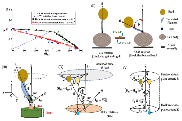
In our model, the most crucial parameter is the bending angle of the hook, (Fig.(1)(II)). We consider here that in CW rotation, hook remains along the direction normal to the cell body surface at the location of the motor [8], represented by the unit vector in Fig.(1)(II); while in absence of CheY-P in CCW-rotation, hook bends due to elasto-hydrodynamic instability[8] and makes an angle [5], between the unit vector along the axis of the filament and (Fig.(1)(II)). Moreover, following [8], a sharp transition of the hook’s stiffness with is contemplated during rotational switching of the motor.
The bending of hook initiates an additional complexity, i.e., it induces two different motions of FB, revolution around and spin around [24]. The origin of these two motions is the torque upon the hook generated by the rotation of the motor [21], which can be orthogonally decomposed into and (Fig.1(III)). The torque along are responsible for the spinning motion of FB with angular velocity , whereas along participates to revolve FB with angular velocity , where and are two orthogonal unit vectors(Fig.1(III)).
Denote and as the components of and , respectively along the direction of , we can write down the torque balance equation of motor:
| (1) |
where is the rotational torque originated from the stator-rotor interaction, and are the rotational drag coefficient and angular velocity of the motor, respectively; and is the Brownian torque acting on the motor with , and are the Boltzmann constant, absolute temperature, and the uncorrelated Brownian noise, respectively.
Similarly, the torque balance equation of FB for the revolution motion is
| (2) |
and for the spinning motion is
| (3) |
where and are the drag coefficients of the FB for these two motions, respectively (for more details, see [25]). Similar to Eq.(1), here in Eq.(2)-(3), and carry the same meaning as . and are the angular velocities of FB for the revolution and spinning motions, respectively.
Once the hook behaves flexibly and bends, the hydrodynamic drag acting on FB makes a delayed movement of it compared to the motor, which is shown in Fig.1(IV) and (V) for the revolution and spinning motions, respectively. However, as FB is attached with the motor through hook, so motor would endeavour to rotate the FB along with the same speed of itself. Consequently, due to elastic nature of the hook, the restoring torques, and would be originated in both motions. Neglecting the inertia of the hook, the torque balance of the hook states that for the revolution motion, , whereas for the spinning motion. Hence we express and as
| (4) |
and
| (5) |
where designate the angular displacement of motor at time , and as well as convey the same meaning of FB for its revolution and spinning motions, respectively. Here, designates the bending stiffness of hook in the XY-plane, whose value becomes equal to the stiffness of hook in the XZ-plane as hook is considered here as an elastic thin tube[25]. For spinning or torsional rotation, in Eq.(5) represents the torsional stiffness of hook,
| (6) |
where [26]. Moreover, we consider the variation of with according to the observation in [8], which is implemented here through a Hill-type equation,
| (7) |
where pN-nm/rad [8] represents the critical bending stiffness of hook and two parameters, and designate the maximum bending angle and stiffness of the versus curve [25]. The result of [8] is incorporated through our proposed equation (eq.(7)) by considering the fact that in CCW rotation of motor, hook remains flexible as , which ensures the ‘run’ motion[8], whereas for CW rotation, resulting the tumble motion of a bacterium [5, 9, 8].
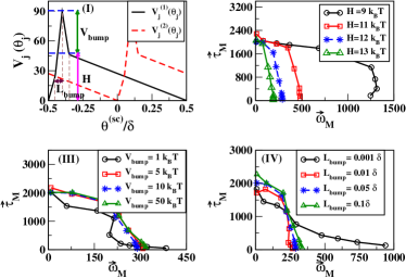
In addition, in this study, we adopt the switching-diffusion type TG mechanism described in [15] for the estimation of in Eq.(1). Two asymmetric free-energy potentials and , with for , are considered to describe the interaction between proteins with protonated and unprotonated conformations of the -th stator, respectively (see Fig.2(I)). is defined as , where is the rotational angle of the -th stator; and the asymmetry in the potentials determine the direction of rotation. The torque with or , and = 8 designates the total number of stators. The conformational switching of stator is described as chemical reactions, i.e.
with transition rates
where are the specific rate coefficients. The potential and the kinetic parameters are adjusted in such a way so that the transition from to or vice-versa follows the tight coupling mechanism between the motor’s rotation and the conformational switching of the stator [15, 25].
Finally, the averaged motor torque is calculated at steady state in the form as
| (8) |
where [25]. The average value of , is numerically calculated by solving Eqs.(1)-(3) combined with Eqs. (4)-(7). At first, the TS relation for CCW rotation is simulated with for , calculated from Eq.(7); and such a value of is supported by [9, 5]. Our simulated TS curve makes a good agreement with the experimentally determined curve [23] (Fig.1(I)).
Next, we would investigate the rationale behind the linear TS relation for CW rotation. Logically, if the asymmetricity entirely depends on the TG mechanism, the linear TS relation should be reproduced through the variation of the parameters of the potential of mean force, i.e. . To examine the possibility, a thorough study is carried out to understand the variation of the nature of the TS relation with the parameters of the potential. In Fig.(2) (II)-(IV), we depict the variation of TS relation for three main parameters, e.g., height of , ; height of the bump of , ; and regulates the span of the bump region. The thorough analysis is provided in [25], and for clear understanding about the meaning of these three parameters, see Fig.(2)(a). Our study reveals the fact that the linear TS relation of CW rotation can never be obtained from the variation of the parameters of . Therefore, we can suggest that the asymmetry in the TS relations for CCW and CW rotations does not solely depend on the TG mechanism.
From our simulation, the linear TS relation for CW rotation, described in [23], can be nicely reproduced (see Fig.1(I)) for for , which is calculated from Eq.(7). Moreover, in Fig.1(I), it can be noticed that the ratio of is same at both CCW and CW modes, which is depicted as a dotted blue line, and consistent with the experimental observation in [23].
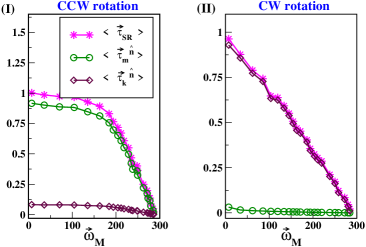
After next, we would scrutinize the reason for this asymmetry. Thus, in Fig.3(I) and (II), the normalized value of , and with respect to the maximum value of are plotted as a function of for CCW and CW rotations, respectively. We observe that in CCW rotation (Fig.3(I)), varies almost equally with , whereas remains very small compare to . Similarly, in CW rotation, and becomes linear with and varies almost equally. However, in this rotational mode, becomes negligible (see Fig.3(II)).
Since in Eq.(1), and , so when approaches to in the CCW rotation, or is expected to be negligible compared to or ; consequently, the revolution motion plays the most significant role in determining the nature of the TS curve. However, when approaches to in the CW rotation, the revolution motion of FB tends to vanish as the radius of the revolution plane goes to zero[25]. Thus, in the CW rotation, only spinning motion of FB predominates, and or mainly modulates the motor torque.
In summary, in this letter, we provide a mechanistic explanation of the experimentally determined asymmetric TS relations for CCW and CW rotations of a BFM. The bending of hook induces the revolution and spinning motions of FB; and consequently, different restoring torques are developed for these two motions due to hydrodynamic drag, which mainly modulate the motor torque generated for the stator-rotor interaction. We consider here that in presence of CheY-P proteins, hook transforms its conformation from flexible to rigid one by changing from to during CCW to CW rotational switching of the motor, which is observed in the in-vivo condition[5]. Only by tuning a single parameter, , our model can fit both of the experimentally determined TS relations of CCW and CW rotations quite well. The study reveals that in CCW rotation, revolution motion predominates, and governs the shape of the TS curve. However, in CW rotation, spinning motion guides the shape of the linear TS relation. Moreover, from our study, we can conclude that the asymmetric TS relationship is not solely dependent on the TG mechanism; rather it’s a consequence of the coupling between the torque-generation mechanism and the conformational changing of the hook due to rotational switching of a BFM. Our study paves the way for further experimental exploration on the structural origin of such asymmetry.
Acknowledgements.
The authors acknowledge Prof. Fan Bai for his assistance at the initial phase of this problem. H. Ge is supported by NSFC (Nos. 11622101 and 11971037).References
- [1] H. C. Berg, Annu. Rev. Biochem. 72, 19 (2003); H. C. Berg, Biophys. J. 68, 1036 (2000).
- [2] D. F. Blair, FEBS Lett. 545, 86 (2003).
- [3] Y. Sowa, and R.M. Berry, Q. Rev. Biophys.41, 103 (2008); Y. Sowa, H. Hotta, M. Homma and A. Ishijima,J. Mol. Biol. 327, 1043 (2003).
- [4] N. C. Darnton, L. Turner, S. Rojevsky, and H.C. Berg, J. Bacteriology. 189, 1756 (2007).
- [5] Brown et al.,J. Bacteriology. 194, 3495 (2012).
- [6] S.B. van Albada, S. Tănase-Nicola, and P. Rein ten Wolde, Mol. Sys. Biol. 5, 316 (2009).
- [7] F. Bai, T. Minamino, Z. Wu, K. Namba, and J. Xing, Phys. Rev. Lett. 108, 178105 (2012).
- [8] E. E. Riley, D. Das, and E. Lauga, Sci. Rep. 8, 10728 (2018).
- [9] S.M. Block, D. F. Blair and H. C. Berg, Nature Lett. 338, 514 (1989).
- [10] K. Paul, D. Brunstetter, S. Titen,and D. Blair, Proc. Natl.Acad.Sci. USA. 108, 17171 (2011).
- [11] M.K. Sarkar, K. Paul, and D. Blair, Proc.Natl.Acad.Sci. USA. 107, 9370 (2010).
- [12] S. Kojima and D. Blair, Biochemistry. 40, 13041 (2001).
- [13] F. Bai, R. W. Branch, D. V. Nicolau Jr., T. Pilizota, B.C. Steel, P.K. Maini, and R.M. Berry, Science 327, 685 (2010).
- [14] F. Bai, C. J. Lo, R. M. Berry, and J. Xing, Biophys. J 96, 3154 (2009).
- [15] J. Xing, F. Bai, R. Berry, and G. Oster, Proc. Natl. Acad. Sci. USA 103, 1260 (2006).
- [16] W. C. Ryu, R. M. Berry, and H. C Berg, Nature Lett. 403, 444 (2000).
- [17] G. Meacci, and Y. Tu, Proc. Natl. Acad. Sci. USA 106, 3746 (2009); G. Meacci, G. Lan, and Y. Tu,Biophys. J. 100, 1986 (2011).
- [18] C. V. Gabel and H. C. Berg, Proc. Natl. Acad. Sci. USA 100, 8748 (2003).
- [19] L. K. Lee, M. A. Ginsburg, C. Crovace, M. Donohoe and D. Stock, Nature 466, 996 (2010).
- [20] H. C. Berg and L. Turner, Biophys. J. 65, 2201 (1993).
- [21] B. G. Hosu, V.S. J. Nathan, and H. C. Berg, Proc. Natl.Acad.Sci. USA. 113, 4783 (2016).
- [22] X. Chen and H. C. Berg, Biophys. J. 78, 1036 (2000).
- [23] J. Yuan, K. A. Fahrner, L. Turner, and H. C. Berg, Proc. Natl. Acad. Sci. USA 107, 12846 (2010).
- [24] Y. Shimogonya, Y. Sawano, H. Wakebe, Y. Inoue, A. Ishijima, and T. Ishikawa, Sci. Rep. 5, 18488 (2015).
- [25] Supplementary Information including more details of the model and parameter values.
- [26] T. C. Flynn, and J. Ma, Biophys.J, 86, 3204, 2004.