Theoretical analysis of glide- magnetic topological photonic crystals
Abstract
Gapped systems with glide symmetry can be characterized by a topological invariant. We study the magnetic photonic crystal with a gap between the second and third lowest bands, which is characterized by the nontrivial glide- topological invariant that can be determined by symmetry-based indicators. We show that under the space group No. (), the topological invariant is equal to a half of the number of photonic bands below the gap, and therefore, the band gap between the second and third lowest bands is always topologically nontrivial, and to realize the topological phase, we need to open a gap for the Dirac point at the point by breaking time-reversal symmetry. With staggered magnetization, the photonic bands are gapped and the photonic crystal becomes topological, whereas with uniform magnetization, a gap does not open, which can be attributed to the minimal band connectivity exceeding two in this case. By introducing the notion of Wyckoff positions, we show how the topological characteristics are determined from the structure of the photonic crystals.
1 Introduction
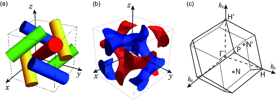
Manipulations of magnetic topological materials are an intriguing and promising topic in condensed matter physics. In particular, a glide-symmetric topological crystalline insulator (TCI) exhibits a topological phase in class A hosting a single surface Dirac cone topological phase with the nontrivial topopogical invariant [1, 2, 3, 4]. One of our targets for material realizations is bosonic systems. In photonics, a new type of topological band-crossing points beyond the Weyl and Dirac points emerges. For example, at a generalized Dirac point [5], the bands are four-fold degenerate and they split into three or four bands along any direction, in contrast with a Dirac points, which generally splits into two sets of double degenerate bands along any direction. When the system is perturbed, this generalized Dirac point becomes line nodes, Weyl points, or opens a band gap [6, 5]. As an example, in the photonic crystal having a structure in the first blue phase of liquid crystals (BPI) [5] shown in Fig. 1, by introducing magnetization to break time-reversal symmetry (TRS) the generalized Dirac point opens a band gap and the system goes into topological phases protected by glide symmetry. On the other hand, in the double gyroid (DG) photonic crystal [6] (Fig. 1(b)) belonging to the same space group (henceforth, we call a space group by its number in bold italic following in Ref. [7]) with the BPI photonic crystal, the system has Weyl points [8] between the fourth and fifth lowest bands in the absence of TRS. Nonetheless, how the band structures and topological properties are determined from the structure of the photonic crystals needs to be clarified.
In the present paper, we show how this topological phase can be manipulated, based on the relationship between space group representations and band structures. In the BPI photonic crystal, the gap opening at non-equivalent and points in the Brillouin zone (BZ) (Fig. 1(c)) makes the system gapped and topologically nontrivial. However, the reason why this structure leads to the topolgical phase, and how the eigenmodes at these and points affect the topological phase is not yet clear. In this paper, we clarify these points, by using the formula of the glide- invariant which we derived in our previous paper [9]. In particular, in the space group , which the photonic crystals in the previous works [6, 5] belong to, the topological invariant is equal to a half of the number of bands below the gap in terms of modulo 2, and therefore, the gap between the second and third lowest bands is always topologically nontrivial. On the other hand, in the presence of the TRS, since all modes at the points are fourfold degenerate, the band gap between the second and the third lowest modes is closed at the point. Therefore, we conclude that when this gap is open by breaking the TRS, the photonic crystal is a topological one protected by the glide symmetry, as has been realized in the BPI photonic crystal [5] with staggered magnetization. We also show that it automatically becomes a higher-order topological insulators [10, 11, 12, 13, 14, 15]. On the other hand, in a uniform magnetization, a gap does not open between the second and third lowest bands, which is explained by the notion of the minimal band connectivity [16]. Then, we propose a way to design such a topological photonic crystal by introducing the notion of Wyckoff positions into the design of photonic crystals.
This paper is organized as follows. Section 2 is devoted to reviewing the previous works necessary for the discussion of the main part of this paper. In Sec. 3, we analyze the irreducible representations of the photonic crystals considered, and discuss which cases will realize topological photonic crystals. In Sec. 4 we introduce the notion of the Wyckoff positions into the design of the photonic crystals, and discuss the relationship between the positions of the dielectrics and topological phases. We conclude the paper in Sec. 5.
2 topological photonic crystal with glide symmetry
In this section, we first review the BPI photonic crystal, which is proposed to be in the topological phase with glide symmetry in Ref. [17], and then we analyze its characteristics from our viewpoint.
2.1 Review on the BPI topological photonic crystal
We consider a 3D photonic crystal in a body-centered cubic (BCC) lattice, composed of four identical dielectric rods. A schematic illustration of the system is shown in Fig. 1(a). We take the , , axes to be parallel to the edges of the cubic unit cell. The four dielectric rods are along the BCC primitive vectors along (111), , and , and they go through the points (0,0,0), (0,0.5,0), (0.5,0,0) and (0,0,0.5), respectively, where is the lattice constant of the cubic cell. The space group is (), which is nonsymmorphic, containing glide reflections and inversion.
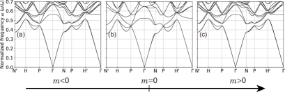
When we set the dielectric constant of the rods to be and the radius of the rods to be , the fourfold generalized Dirac point appears at two non-equivalent points in the BZ formed by the bands 1, 2, 3 and 4 counted from the lowest band (Fig. 2(b)), because of the cubic and time-reversal (TR) symmetries [5]. If the magnetization is present in these rods with the glide symmetry preserved, the band structure acquires a band gap between bands 2 and 3 by breaking the TRS and it becomes the topological phase with the nontrivial topopogical invariant [1, 2, 3] protected by glide symmetry [5]. To be more specific, in the dielectric tensor of the rod , we add off-diagonal imaginary terms , which breaks TRS,
| (1) |
where and are dielectric constants with [5, 6], and is a non-zero imaginary number. These off-diagonal imaginary terms lead to gyroelectric response of materials [18]. Similarly, gyromagnetic response in ferrites is generated by off-diagonal terms of the permeability tensor [19]. In the calculation, the off-diagonal terms are introduced in a staggered way as with for the dielectric rods along (111) (red), (yellow), (blue) and (green) shown in Fig. 1(a). In Fig. 2(a) and (c), we show the band structures of the BPI photonic crystal with these two patterns of the sign of , with the rod along the (111) direction having , respectively. This value of does not reflect that in real materials, but is only for demonstration of the behaviors of the gap. At preserving TRS, a four-fold degenerate generalized Dirac point exists at the point (Fig. 2(b)). Then by breaking the TRS via nonzero , a band gap opens between the bands 2 and 3 at the points, and both of these cases with are found to be topological in Ref. [5].
2.2 Discussion on symmetry and topology of the topological photonic crystal
Thus, regardless of the sign of , the band gap opens at the point and this gap becomes topological. This is related with the fact that the irreducible representations (irreps) at the points do not affect the values of the topological invariant; namely, the gap at is inverted between and , but it does not affect the topological invariant. This situation is similar to the Kane-Mele model, which is a well-known model for the two-dimensional topological insulator (TI) phase with TRS [20, 21]. The Kane-Mele model is topological, regardless of the sign of the spin-orbit coupling , which opens the gap at the point. Thus both in the BPI photonic crystal and in the Kane-Mele model, the topological invariant is independent of the irreps at or points, and regardless of the sign of the parameter ( or ) to open a gap, the system becomes topological as long as the parameter is nonzero. More details are presented in Sec. S1 in the Supplemental Document.
3 Symmetry consideration for band theory of glide-symmetric magnetic topological photonic crystal
In this section, we discuss what determines the topological invariant in the photonic crystal from the symmetry viewpoint. We first investigate the irreps for the glide-symmetric magnetic topological photonic crystals, i.e. the BPI [5], and DG [6] photonic crystals. Then, we calculate the glide- invariant by using our new formula derived in Ref. [9].
3.1 Representations at the high-symmetry points from symmetry considerations
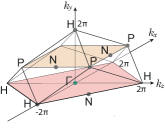
We first explain irreps at high-symmetry points in the BZ in the space group No. . There are four kinds of high-symmetry points , , , and in the BZ (see Fig. 4 (c)). Among these four high-symmetry points, the points , , and are TRIMs in BZ, but is not. Even though is not a TRIM, the bands at the point should be degenerate in the presence of TRS. This double degeneracy comes from combined symmetry where is time-reversal operation, and is the glide symmetry , where and denote the unit vectors along and directions, respectively. As is an antiunitary symmetry, and it satisfies at the point, where , and is an identity operation, the bands are always doubly degenerate at the point.
Our strategy is the following. We first start with a vacuum having a homogeneous dielectric constant . Thereby, the eigenmodes behave as electromagnetic plane waves with a linear polarization in free space. From symmetry considerations for these plane-wave basis functions, we can identify representations at high-symmetry points which characterize the eigenmodes at (Fig. 3(a)). Next, we gradually increase the dielectric constant from within the dielectrics to describe a photonic crystal. Then, the eigenmodes split into irreps at the high-symmetry points in the BZ, from which we discuss the topological invariant.
As an example, let us consider the six points , , and we call them points. They are the smallest wavevectors among the points in -space. At these points the basis functions are formed by the 12 plane waves in free space for the six wavevectors having two polarizations each. These basis functions are decomposed into irreps as summarized in Table 1, by using the character table for the irreps of the point summarized in Table S3 in Supplemental Document. Therefore, the eigenmodes with the lowest frequency at the points are decomposed into irreps , where and are degenerate in the presence of TRS.
3.2 Representations at the high-symmetry points in the BPI and DG photonic crystals
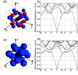
This result based on the plane waves matches with our numerical calculations for the BPI and the DG photonic crystals with various values of the dielectric constant , as shown in Fig. 3. The lowest four modes for the vacuum in Fig. 3(a) splits into in both the BPI and the DG photonic crystals with increasing the dielectric constants of the dielectrics. In the same manner, one can classify the irreps for the several lowest frequencies at the high-symmetry points such as , and . These results are summarized in Table S1 in Supplemental Document.
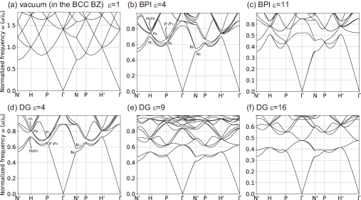
Let us discuss the change of the band structure and the irreps in the BPI photonic crystal, when the dielectric constant in photonic crystal is varied from 1 (Fig. 3(a)) via 4 (Fig. 3(b)) to 11 (Fig. 3(c)). The degeneracies at the high-symmetry points such as , and at are split into irreps in Table S1 when is increased. In this case, the irreps of the lowest bands at high-symmetry points are given by , , and summarized in Table. 2. These irreps remain the lowest bands even up to .
On the other hand, behaviors of the DG photonic crystal are different from that in the BPI photonic crystal. The DG photonic crystal is shown in Fig. 1(b) whose space group is , being the same as the BPI photonic crystal. The single gyroid surface is given by an isosurface of
| (2) |
where is the lattice constant in the BCC lattice [22], and the DG surfaces are given by isosurfaces of and of its counterpart by space inversion, . We set the dielectric regions as and with , shown in blue and red, respectively in Fig. 1(b). From our results on the band structures when the dielectric constant is changed from 1 (Fig. 3(a)) via 4 (Fig. 3(d)) and 9 (Fig. 3(e)) to 16 (Fig. 3(f)), the irreps of the four lowest bands at high-symmetry points are given by , , and which are summarized in Table 2. This set of the irreps are different from the BPI photonic crystals.
3.3 Photonic waves at the point in photonic bands
We have been focusing on the glide- invariant for the lowest two bands of this photonic crystal. Here, although the electromagnetic waves are singular at as mentioned in Ref. [16], one can identify their symmetry properties near , which are needed for calculation of the topological invariant. First, the electromagnetic waves in a homogeneous isotropic medium are written analytically. Then, as remarked in Ref. [16], even in photonic crystals, the electromagnetic waves near behave similarly with those in a homogeneous isotropic medium, because in the longwavelength limit, the spatial variation of the dielectric constants in the photonic crystal will become irrelevant. In the next subsection, we show how we calculate the symmetry property of the waves around the singularity at within our theory.
3.4 Glide- invariant for the photonic crystal
In magnetic glide-symmetric systems, the glide- topological invariant can be defined, which characterizes a topological crystalline insulator phase [1, 2, 3]. In Ref. [5], the BPI photonic crystal is proposed to be in the topological phase ensured by this glide- topological invariant, but a physical reason why this structure leads to the topological phase is unknown. Here we show this reason by directly studying the formula of the glide- topological invariant.
The glide- topological invariant is defined in a crystal with glide symmetry, and its formula is expressed as a sum of line and surface integrals in -space [1, 2, 3], which is not easy to evaluate numerically. On the other hand, when inversion symmetry is preserved, like the photonic crystals of our interest, its formula is drastically simplified, and it is expressed in terms of the irreps at high-symmetry points[9] in the form of a symmetry-based indicator [23, 24]; thus it is much easier to evaluate. In the space group , which our photonic crystals belong to, we obtain a formula for the glide- topological invariant , associated with a certain band gap, as
| (3) |
where the product is taken over the bands below the gap considered, is a eigenvalue in the glide sector with a glide eigenvalue , is an inversion parity for the -th occupied state, and the product runs over the bands below the gap considered. The detailed derivation of this formula is presented in Section S2 in the Supplemental Document. The value of is either or , corresponding to the topologically trivial and nontrivial phases, respectively. The high-symmetry points in the Brillouin zones for are shown in Fig. 4. We note that from Eq. (3), the irreps at the point in do not contribute to the glide- invariant, as we mentioned in the last part of the Section 2.
Remarkably, in , the formula (3) for the topological invariant is further simplified drastically, by evaluating Eq. (3) term by term. In this calculation, we focus on the band gap between the second and third bands, when TRS is broken by applying a magnetic field. First, the point has three possible physically irreducible representations, , , and , and all of them yield , by a direct calculation from Table S4 in Supplemental Document. Second, the point has two possible physically irreducible representations, and . Both of them contributreare to the product in Eq. (3) by a factor . Therefore, the total contribution from the point is , where is the number of bands below the gap considered. Third, as noted earlier, the eigenmodes with at the point are special in any photonic crystals because of the transversality condition of the electromagnetic wave, and they do not follow the ten irreps at the point. Through a direct calculation, we show that it contributes trivially (i.e. by a factor ) to the product in Eq. (3). To summarize, the glide- invariant for is calculated as
| (4) |
It means that when the number of bands below the gap is (: integer), the photonic crystal is topologically nontrivial, and when it is (: integer), it is topologically trivial, provided the gap is open everywhere in the Brillouin zone.
At the point, there are two possible physically irreps under the TRS, and , both of which are four-dimensional. Therefore, when (i.e. ), there is no gap at the point when the TRS is preserved. Therefore we need to open a gap at by breaking TRS to make it topologically nontrivial. On the other hand, when (i.e. ), the point is gapped. Here, the and irreps lead to the doubly degenerate Dirac point, and the generalized Dirac point, respectively, and in both cases, quad-helicoid surface states are realized on the (001) surface, thanks to the combination of the two glides and the time-reversal symmetries [25, 26], and another topological invariant, which we call a helicoid- invariant, could be defined to represent nontrivial winding of the helicoid surface states. How the helicoid- and glide- are mutually related is an open question.
Thus far, we have understood how to make the glide- topological invariant nontrivial. To make the photonic crystal topological, it is important how we break the TRS, i.e. how we introduce magnetization into dielectrics. Here we introduce two types of magnetizations employed in the previous works, and we call these types I and II. The type I is realized in the BPI photonic crystal with the two dielectric rods (red and yellow in Fig. 1) having magnetization, and the other two (blue and green in Fig. 1) having magnetization, as employed in Ref. [5]. It is classified as the magnetic space group (MSG) , whose list is in the Bilbao Crystallographic Server [27]. The type II is the DG photonic crystal with the uniform magnetization along the direction employed in Ref. [6], which belongs to the MSG . As we have seen in this paper, the photonic crystal is in the topological phase, if a gap is open between the second and the third lowest bands. From an argument based on band topology, we conclude that in the type I the photonic crystal opens a gap between the second and third lowest bands everywhere in -space, while in the type II, the photonic crystal does not open a gap. This is explained by extending the notion of minimal band connectivity for a nonmagnetic photonic crystal in Ref. [16] into magnetic photonic crystals, whose details are shown in Section S2 in the Supplemental Document. This conclusion fully agrees with the results in Refs. [5, 6], saying that the BPI photonic crystal is in a topological insulator phase ensured by glide symmetry for the gap between the second and the third bands, while the DG photonic crystal does not open a gap.
We note that in general, some other symmetries apart from glide symmetries can give topological surface modes. For example, mirror symmetry can give us topological phases associated with a mirror Chern number, leading to topological surface modes in the gap [28]. Meanwhile, the space group , which we study in this paper, contains various symmetries such as threefold rotations and twofold screw rotations other than glide symmetries, but none of the other symmetries except for glide symmetries are associated with topological surface modes. Thus in this space group , the band gap topology solely depends on the glide symmetry.
4 Design of topological photonic crystals with glide symmetry
So far we have seen how the topological properties of these photonic bands are understood in terms of the irreps at high-symmetry points in -space. In this section, we propose how topological photonic crystals are designed, based on the representation theory and Wyckoff positions. In particular, we focus on the BPI and DG photonic crystals as two characterisitic examples, and how the photonic bands of these photonic crystals result from their structure in real space. To show this we focus on the irreps at the point, and as we noted, in the BPI photonic crystal, the irrep is the lowest, while in the DG photonic crystal, the irreps are the lowest.
4.1 Perturbation theory
As we argued in the previous section, the irreps for the lowest bands at the point for the BPI photonic crystal and DG photonic crystal are unchanged by a change of the dielectric constant from unity to a larger value. We need to see how the level splitting occurs at the point by increasing . In order to see the level splitting at the point for a value of close to unity, we can employ the perturbation theory in the dielectric function. When we add a small perturbation of the dielectric function , the frequency shift is given to the first order in the perturbation as follows [29]:
| (5) |
This relation implies that when the electric field is more concentrated within the dielectrics with having nonzero , the frequency shift increases.
We apply this formula to the lowest bands at the point. To this end we use the 12 plane wave basis functions at the lowest frequency at the points, decomposed into a set of eigenstates following the irreps , , , and , as summarized in Table 1. Then, we can calculate the frequency shift by using Eq. (5), if we know the spatial distribution of corresponding to a photonic crystal. As a result, within the first-order perturbation theory in Eq. (5), one cannot determine the difference of the frequency shifts for the irreps , and in Table 1, because the distribution of in Eq. (5) is identically the same for , and . Here, the reason why the degeneracy is not lifted in the first order in is because of the high symmetry of the cubic space group. We expect that in the higher order in the perturbation , this degeneracy will be lifted, as required from the space-group symmetry. In order to see how this degeneracy is lifted, we perform numerical calculations in the next subsection, instead of developing the higher-order perturbation theory, which is lengthy and complicated.
4.2 Photonic band structures based on Wyckoff positions
So far we have seen that in the present case it is not easy to see relationships between the structure of the photonic crystal and the band structure in an analytic way. Therefore, we approach this problem with numerical calculations. Here, we introduce the notion of Wyckoff positions, often used in the context of electronic systems. In electronic systems, Wyckoff positions classify spatial locations consistent with a given space group. By putting orbitals with various symmetry properties at the Wyckoff positions, one can exhaust all the band structures of atomic insulators. Inspired by this, we adopt the concept of the Wyckoff positions into our theoretical analysis on photonic crystals.
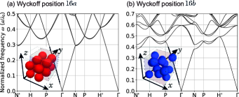
There are 8 kinds of Wyckoff positions in and their site symmetries are summarized in Table 3 [7]. Their positions for , and are in Table 4, and other Wyckoff positions are summarized in Table S5 in Supplemental Document. Our objective is to find which Wyckoff positions correspond to the band structure of the BPI and to that of the DG photonic crystals. To this end, we numerically calculate the band structure by putting dielectric spheres on a given Wyckoff position. When dielectric spheres are absent, the light propagates in vacuum whose band structure is the same in Fig. 3(a), but if the dielectric spheres have a finite radius, the band structure changes, depending on the positions of the dielectric spheres.
First, we put dielectric spheres at the Wyckoff positions labeled , which are located at and with being integers, according to Table 4. We here set the dielectric constant of the dielectric spheres to be . We set the radius of the dielectric spheres to be the maximum one, i.e the radius when they touch each other. In this case, the band structure hardly changes from that for vacuum as seen from Fig. 5(a). Recall that Eq. (5) implies the degree of concentration of the electric fields in the dielectric regions. Since the splitting of frequencies among the eigenmodes with and in the case of the Wyckoff position (in Fig. 5(a)) are not conspicuous, the electromagnetic waves in these eigenmodes are localized on the dielectric spheres at the Wyckoff position to the same degree.
In the similar manner, we can calculate the corresponding band structures for dielectric spheres at other Wyckoff positions in , listed in Table 3. As a consequence, we find that dielectric spheres at the Wyckoff positions labeled by , and generate band structure, with being the lowest bands at , similar to that from the DG photonic crystal, and the Wyckoff position labeled by generates band structure with being the lowest bands at , similar to that from the BPI photonic crystal. For the Wyckoff position , the eigenmodes for and are also very close to each other, while they are away from those for . The lowest eight bands at the point and those at the point hardly split. For the Wyckoff position , the band structure hardly changes from vacuum. We skip the most general Wyckoff position , because no special feature from symmetry is expected. Remarkable cases are depicted in Fig. 5, where we set the dielectric constant as and the radius of dielectric spheres as for (Fig. 5(a)) and for (Fig. 5(b)) with the lattice constant being unity.
Let us compare these results with the BPI and DG photonic crystals in the related previous works. In the BPI photonic crystals, the dielectric rods lie along the and directions, which corresponds to the Wyckoff position , with changing the free parameter in Table 4. Indeed, the photonic crystal with dielectric spheres at the Wyckoff position was shown to have as the lowest band (see Table 3), similar to the BPI photonic crystal.
Next we discuss the DG photonic crystal with dielectrics located at and where is defined in Eq. (2). The isosurface function has a maximum value when is equal to the Wyckoff position . By changing smaller from , the dielectric regions for the DG photonic crystal broaden from the sites of along toward , i.e., along the planes perpendicular to the four rotation axes. Indeed, in the band structures for , and , the lowest bands follow the irreps, and their band structures are simiar to that of the DG photonic crystal.
4.3 Design of topological photonic crystals based on Wyckoff positions
We have shown that dielectric spheres located at the Wyckoff position in generates band structures, similar to the BPI photonic crystal, while those at in generates band structures similar to the DG photonic crystal. Now we discuss how these two cases are related if we gradually change the structure of the photonic crystal between the two cases. To this end, we focus on the Wyckoff positions, and , which are regarded as special cases of the Wyckoff position 32 by setting and , repsectively (see Table 4)
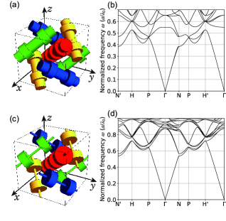
First, we examine band structures for photonic crystals with dielectric spheres both at and at for various values of their radii. Let and denote the radii of dielectric spheres at the Wyckoff positions and , respectively, and we change and , with keeping the spheres touching each other, which leads to a constraint . Henceforth, we set the lattice constant to be unity. Let us start with . The configuration is depicted in Fig. 6(a) where the gray cuboid represents a conventional unit cell , and the band structure is shown in Figs. 6(b). The band structure qualitatively agrees with that of the BPI photonic crystal, having the rods along the Wyckoff position (Fig. 2(b)), because the structure is similar to that of the BPI photonic crystal with dielectrics at , as can be seen in from Fig. 6(a). Next, we make the system similar to the photonic crystal with spheres at , by putting and depicted in Fig. 6(c). Then the band structure is given in Figs. 6(d). In this case, the band structure qualitatively agrees with that of the DG photonic crystal having dielectrics mainly at 16.
As another example, we also consider photonic crystals with dielectric cylinders, in order to see how the band structures changes between the two cases. We combine two species of cylinders, one along and the other centered at with sharing their axes in common, and we consider the dielectrics located inside the union of these sets of cylinders. We fix the height and radius of dielectric cylinders at as and , and change the radius of dielectric cylinders with an infinite height along . In the case of shown in Fig. 7(a), where the photonic crystal is almost identical with the BPI photonic crystal, the band structure with TRS in Fig. 7(b) is similar to that of the BPI photonic crystal, as we intuitively expected, with the lowest bands identical with those for the BPI photonic crystal in Table 2. On the other hand, in the photonic crystal with in Fig. 7(c), where the dielectrics are localized around the Wyckoff position , the band structure is shown in Fig. 7(d), and is similar to that of the DG photonic crystal, as listed in Table 2. These results show that by classifying the photonic crystals in terms of the Wyckoff positions of the dielectrics, one can predict the ordering of irreps at high-symmetry points (see Table 3). Thus, photonic crystals with dielectrics at various Wyckoff positions can serve as building blocks to find ones with desired band ordering at high-symmetry positions, and it can be a way to “design” photonic crystals with desired properties.
Now we discuss universality and limitation of the method of designing topological photonic crystals based on Wyckoff positions. We consider that our analysis in terms of Wyckoff positions works well in the perturbative regime discussed in Sec. 4.1, where the dielectric constant of the dielectrics is close to that of vacuum. Indeed, in the present paper, we show that the ordering of the irreps of the bands can be predicted from the Wyckoff positions of the dielectrics, as summarized in Table 3, and it universally holds as long as the dielectric constant is close to that of vacuum. If the dielectric constant of the dielectrics become larger, various bands with different irreps can be inverted and the band ordering may differ from that in Table 3.
5 Conclusion and discussion
In the present paper, by investigating the relationship between band structures and space group representations, we study how to manipulate topological photonic crystals ensured by glide symmetry. In particular, for the BPI photonic crystal without time-reversal symmetry, which is proposed to realize the glide- magnetic topological crystalline insulator phase in the previous paper, we explain the physical reason of the topological phase by using our new formula of the glide- invariant in terms of irreducible representations. By comparing band structures and irreps at high-symmetry points in our numerical calculation, we have also figured out that the photonic crystal with realizes the glide- magnetic topological phase only from symmetry considerations. In such photonic crystal designed in this way, by opening the gap between the second and third bands by breaking time-reversal symmetry in a staggered way (type I in the main text), we always obtain the glide- topological crystalline insulator.
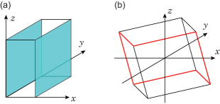
Moreover, because the glide- topological crystalline insulator phase is automatically the higher-order topological insulator in the presence of inversion symmetry, such glide- topological photonic crystals discussed in this paper are higher-order topological insulators, and one can expect topological hinge states [3]. Under the glide operation , the surface preserves glide symmetry and the topological surface states of the glide- topological phase emerge on this surface (Fig. 8(a)). On the other hand, if one consider a photonic crystal with an inversion-symmetric shape without glide-symmetric surfaces, the topological surface states do not appear, while hinge states appear because inversion symmetry is still preserved (Fig. 8(b)) [30, 17, 31]. This can be demonstrated by using a simple tight-binding model in Supplemental Document. In electronic systems, it has been proposed that MnBi2nTe3n+1 and support gapless surface states ensured by glide symmetry and hinge states ensured by inversion symmetry [32, 33, 34].
There remain several issues. First, it is generaly difficult to open a common gap throughout the whole Brillouin zone, because the gap induced by breaking time-reversal symmetry is small in general. If the dielectric constant in the dielectrics is perturbatively introduced, , , the lowest frequency at the point is always higher than that at the point, because the - distance is larger than the - distance in space. Even when the dielectric constant in the dielectrics becomes larger, the frequencies of the lowest bands at and are different, which means that a large TRS-breaking term is required to open a large gap.
In this paper, we focused on the topological photonic crystals protected by glide symmetry by breaking TRS. On the other hand, magnons in a magnet form band structure without TRS, and it can also be described by the same topological invariant. Therefore, we can use Eq. (3) to identify the glide- topological invariant when inversion symmetry is present. As an example, we can apply our theory to magnons in yttrium iron garnet (YIG), a ferromagnetic material belonging to the same space group . Nonetheless, so far the band structure of YIG has not been investigated enough for our purpose. According to Ref. [35], the degree of degeneracy for the lowest bands at the point in the magnon band structure looks higher than four, which means that the irreps are not fully resolved, partially because of numerical difficulty due to the complex lattice structure having many atoms per unit cell. Thus, topological characterization of magnons in YIG remains a future work.
Funding Japan Society for the Promotion of Science (JP17J10672, JP18H03678, JP20H04633); National Key R&D Program of China (2017YFA0303800, 2016YFA0302400); Natural Science Foundation of China (12025409, 11721404, 11974415); Strategic Priority Research Program (XDB33000000); international partnership program (112111KYSB20200024); Beijing Natural Science Foundation (Z200008).
Acknowledgments H. K. is supported by Japan Society for the Promotion of Science (JSPS) KAKENHI Grant-in-Aid for JSPS Fellows Grant No. JP17J10672. This work was supported by JSPS KAKENHI Grant No. JP18H03678 and JP20H04633. Ling Lu was supported by the National Key R&D Program of China (2017YFA0303800, 2016YFA0302400), by Natural Science Foundation of China (12025409, 11721404, 11974415), by the Strategic Priority Research Program (XDB33000000) and the international partnership program (112111KYSB20200024) between the Chinese Academy of Sciences and the Croucher Foundation, and by Beijing Natural Science Foundation (Z200008).
Disclosures The authors declare no conflicts of interest.
Data availability statement Data underlying the results presented in this paper are not publicly available at this time but may be obtained from the authors upon reasonable request.
Supplemental document See Supplement 1 for supporting content.
References
- [1] C. Fang and L. Fu, “New classes of three-dimensional topological crystalline insulators: Nonsymmorphic and magnetic,” Phys. Rev. B 91, 161105(R) (2015).
- [2] K. Shiozaki, M. Sato, and K. Gomi, “ topology in nonsymmorphic crystalline insulators: Möbius twist in surface states,” Phys. Rev. B 91, 155120 (2015).
- [3] H. Kim, K. Shiozaki, and S. Murakami, “Glide-symmetric magnetic topological crystalline insulators with inversion symmetry,” Phys. Rev. B 100, 165202 (2019).
- [4] K. Shiozaki, M. Sato, and K. Gomi, “Atiyah-Hirzebruch spectral sequence in band topology: General formalism and topological invariants for 230 space groups,” arXiv preprint arXiv:1802.06694 (2018).
- [5] L. Lu, C. Fang, L. Fu, S. G. Johnson, J. D. Joannopoulos, and M. Soljačić, “Symmetry-protected topological photonic crystal in three dimensions,” Nat. Phys. 12, 337–340 (2016).
- [6] L. Lu, L. Fu, J. D. Joannopoulos, and M. Soljačić, “Weyl points and line nodes in gyroid photonic crystals,” Nature Photonics 7, 294–299 (2013).
- [7] T. Hahn, International Tables for Crystallography, Volume A: Space Group Symmetry, International Tables for Crystallography (Kluwer Academic Publishers, 2002), 5th ed.
- [8] S. Murakami, “Phase transition between the quantum spin Hall and insulator phases in 3d: emergence of a topological gapless phase,” New Journal of Physics 9, 356 (2007).
- [9] H. Kim and S. Murakami, “Glide-symmetric topological crystalline insulator phase in a nonprimitive lattice,” Phys. Rev. B 102, 195202 (2020).
- [10] Z. Song, Z. Fang, and C. Fang, “-dimensional edge states of rotation symmetry protected topological states,” Phys. Rev. Lett. 119, 246402 (2017).
- [11] F. Schindler, Z. Wang, M. G. Vergniory, A. M. Cook, A. Murani, S. Sengupta, A. Y. Kasumov, R. Deblock, S. Jeon, I. Drozdov et al., “Higher-order topology in bismuth,” Nat. Phys. 14, 918–924 (2018).
- [12] W. A. Benalcazar, B. A. Bernevig, and T. L. Hughes, “Quantized electric multipole insulators,” Science 357, 61–66 (2017).
- [13] W. A. Benalcazar, B. A. Bernevig, and T. L. Hughes, “Electric multipole moments, topological multipole moment pumping, and chiral hinge states in crystalline insulators,” Phys. Rev. B 96, 245115 (2017).
- [14] J. Langbehn, Y. Peng, L. Trifunovic, F. von Oppen, and P. W. Brouwer, “Reflection-symmetric second-order topological insulators and superconductors,” Phys. Rev. Lett. 119, 246401 (2017).
- [15] F. Schindler, A. M. Cook, M. G. Vergniory, Z. Wang, S. S. Parkin, B. A. Bernevig, and T. Neupert, “Higher-order topological insulators,” Sci. Adv. 4, eaat0346 (2018).
- [16] H. Watanabe and L. Lu, “Space group theory of photonic bands,” Phys. Rev. Lett. 121, 263903 (2018).
- [17] R. Takahashi, Y. Tanaka, and S. Murakami, “Bulk-edge and bulk-hinge correspondence in inversion-symmetric insulators,” Phys. Rev. Research 2, 013300 (2020).
- [18] F. D. M. Haldane and S. Raghu, “Possible realization of directional optical waveguides in photonic crystals with broken time-reversal symmetry,” Phys. Rev. Lett. 100, 013904 (2008).
- [19] Z. Wang, Y. Chong, J. D. Joannopoulos, and M. Soljačić, “Observation of unidirectional backscattering-immune topological electromagnetic states,” Nature 461, 772–775 (2009).
- [20] C. L. Kane and E. J. Mele, “ topological order and the quantum spin Hall effect,” Phys. Rev. Lett. 95, 146802 (2005).
- [21] C. L. Kane and E. J. Mele, “Quantum spin Hall effect in graphene,” Phys. Rev. Lett. 95, 226801 (2005).
- [22] M. Wohlgemuth, N. Yufa, J. Hoffman, and E. L. Thomas, “Triply periodic bicontinuous cubic microdomain morphologies by symmetries,” Macromolecules 34, 6083–6089 (2001).
- [23] H. C. Po, A. Vishwanath, and H. Watanabe, “Symmetry-based indicators of band topology in the 230 space groups,” Nat. Commun. 8, 50 (2017).
- [24] B. Bradlyn, L. Elcoro, J. Cano, M. Vergniory, Z. Wang, C. Felser, M. Aroyo, and B. A. Bernevig, “Topological quantum chemistry,” Nature 547, 298–305 (2017).
- [25] L. Lu, C. Fang, T. H. Hsieh, L. Fu, S. G. Johnson, J. D. Joannopoulos, and M. Soljačić, “Generalized threedimensional Dirac points and Z2 gapless surface states in a topological photonic crystal,” CLEO:2015 p. FTh3D.7. (2015).
- [26] H. Cheng, Y. Sha, R. Liu, C. Fang, and L. Lu, “Discovering topological surface states of Dirac points,” Phys. Rev. Lett. 124, 104301 (2020).
- [27] M. I. Aroyo, J. M. Perez-Mato, C. Capillas, E. Kroumova, S. Ivantchev, G. Madariaga, A. Kirov, and H. Wondratschek, “Bilbao crystallographic server: I. databases and crystallographic computing programs,” Zeitschrift für Kristallographie-Crystalline Materials 221, 15–27 (2006).
- [28] J. C. Y. Teo, L. Fu, and C. L. Kane, “Surface states and topological invariants in three-dimensional topological insulators: Application to ,” Phys. Rev. B 78, 045426 (2008).
- [29] J. D. Joannopoulos, S. G. Johnson, J. N. Winn, and R. D. Meade, Molding the flow of light (Princeton University, USA, 2008).
- [30] Y. Tanaka, R. Takahashi, T. Zhang, and S. Murakami, “Theory of inversion- protected topological chiral hinge states and its applications to layered antiferromagnets,” Phys. Rev. Research 2, 043274 (2020).
- [31] Y. Tanaka, R. Takahashi, and S. Murakami, “Appearance of hinge states in second-order topological insulators via the cutting procedure,” Phys. Rev. B 101, 115120 (2020).
- [32] Y. Xu, Z. Song, Z. Wang, H. Weng, and X. Dai, “Higher-order topology of the axion insulator As2,” Phys. Rev. Lett. 122, 256402 (2019).
- [33] H. Li, S.-Y. Gao, S.-F. Duan, Y.-F. Xu, K.-J. Zhu, S.-J. Tian, J.-C. Gao, W.-H. Fan, Z.-C. Rao, J.-R. Huang, J.-J. Li, D.-Y. Yan, Z.-T. Liu, W.-L. Liu, Y.-B. Huang, Y.-L. Li, Y. Liu, G.-B. Zhang, P. Zhang, T. Kondo, S. Shin, H.-C. Lei, Y.-G. Shi, W.-T. Zhang, H.-M. Weng, T. Qian, and H. Ding, “Dirac surface states in intrinsic magnetic topological insulators EuSn2As2 and MnBi2nT3n+1,” Phys. Rev. X 9, 041039 (2019).
- [34] R.-X. Zhang, F. Wu, and S. Das Sarma, “Möbius insulator and higher-order topology in ,” Phys. Rev. Lett. 124, 136407 (2020).
- [35] A. J. Princep, R. A. Ewings, S. Ward, S. Tóth, C. Dubs, D. Prabhakaran, and A. T. Boothroyd, “The full magnon spectrum of yttrium iron garnet,” npj Quantum Materials 2, 63 (2017).