Supersymmetry-enhanced Stark-Chirped Rapid-Adiabatic-Passage in multimode optical waveguides
Abstract
We propose a method to efficiently pump an excited mode of a multimode optical waveguide starting from a fundamental-mode input by combining Stark-Chirped Rapid Adiabatic Passage (SCRAP) and Supersymmetry (SUSY) transformations. In a two-waveguide set, we implement SCRAP by modulating the core refractive index of one waveguide, which is evanescently coupled to its SUSY partner. SCRAP provides an efficient transfer of light intensity between the modes of different waveguides, while SUSY allows to control which modes are supported. Using both techniques allows to achieve fidelities above 99% for the pumping of the excited mode of a two-mode waveguide. Additionally, we show that SCRAP can be exploited to spatially separate superpositions of fundamental and excited modes, and how SUSY can also improve the results for this application.
I Introduction
Multimode optical waveguides and fibers [1] provide a solution to the increasing demand of transmission capacity for optical devices [2]. Compared with single-mode waveguides, they offer an effective additional dimensionality to the system by allowing to use each guided mode as an independent information channel. This is known as Mode-Division Multiplexing (MDM) [3, 4, 5, 6], one of the different Multiplexing techniques that have been developed to increase the transmission possibilities of these optical devices [7]. The advantages that MDM provides, however, are limited by the challenging need to precisely excite the desired guided modes by matching the input field to the modes’ spatial profiles. Although several techniques for this purpose exist, they either rely on carefully shaping the input pulse through e.g. spatial light modulators or phase plates [8], or on a specific design for the propagating medium with e.g. optical fibers featuring gratings or multiple cores [9, 8]. In that sense, the possibility of precisely pumping excited modes of general multimode waveguides without the need of complicated input fields is of high interest for current and future applications.
A method that can be used to transfer light into the excited modes of a multimode waveguide is Stark-Chirped Rapid-Adiabatic-Passage (SCRAP). The method was first introduced in Ref. [10] for the transfer of population to a metastable atomic state using a two-pulse scheme, and has since then been extensively studied in several cases [11, 12, 13] and generalized to three-level systems [14, 15, 16, 17]. A strong off-resonant Stark pulse modifies the energies of a two-level system, producing two energy crossings. A short but intense pump pulse then adiabatically drives the population from the initial to the target state during only one of these crossings, while remaining negligible during the other. This scheme can be implemented in optical waveguides setups to achieve faithful transfer of light between guided modes. In this case, the role of the energy eigenvalues is played by the propagation constants of the modes, whose variation is achieved through a modulation of the refractive index of the waveguide core. The transfer is then controlled by the coupling strength between the waveguide modes, which can be tuned by adjusting the relative distance between waveguides.
In the context of optics, Supersymmetry (SUSY) has been successfully employed for instance to control the modal content of different structures [18, 19, 20, 21, 22, 23, 24, 25, 26], their scattering properties [27, 28, 29, 30, 31] and their topology [32]. For multimode optical waveguides, one can obtain a superpartner refractive index profile whose guided modes share propagation constants with the original waveguide, but where the fundamental mode is removed from the spectrum. In conjunction with SCRAP, this modal control allows to achieve transfer to only specific modes in a multimode waveguide, and thus be able to pump them efficiently.
Our objective is to show how the combination of SCRAP and SUSY can be exploited to faithfully pump excited modes of multimode waveguides and to spatially separate superpositions of different modes, both challenges of high importance in the context of MDM. The work is organized as follows: In section II, we present the theoretical basis behind SCRAP and SUSY. After that, in section III we describe their implementation using multimode optical waveguides. We display our results in section IV, where we report the fidelities of the above-mentioned applications, and finally we lay out our conclusions in section V.
II Theory
II.1 Stark-Chirped Rapid-Adiabatic-Passage

 \phantomcaption
We study the implementation of the SCRAP method in a system of two planar evanescently coupled optical waveguides, each one supporting two TE modes. Modes of different order have their coupling suppressed both for energy and parity reasons, so one can describe the propagation of modes of the same order independently of the rest. The equation describing light propagation in such a system of two multimode waveguides then is:
| (1) |
where are the probability amplitudes of mode in the left and right waveguide, respectively. The Hamiltonian is defined as:
| (2) |
where is the coupling between the modes of each waveguide and the detuning is the difference between the propagation constants in both waveguides, , with being the initial detuning and its variation along . The coupling strength and the detuning play here the role of the Rabi frequency and the Stark pulse, respectively, in the original SCRAP implementation [10]. We will consider a Gaussian dependence on for both and , as displayed in Fig. 1. The modulation of causes two level crossings at the points indicated by vertical dotted lines, see Fig. 1, and we choose to be strong during the first crossing and weak during the second.
One can diagonalize the Hamiltonian corresponding to each pair of modes , Eq. (2), obtaining the following eigenvectors and eigenvalues:
| (3) | |||
| (4) | |||
| (5) |
where and are the diabatic states in each waveguide, and defines the mixing angle. Under the modulation of and in Fig. 1, the mixing angle evolves from to . Thus, if light is injected in the left waveguide, the system adiabatically follows from - to , achieving complete light intensity transfer to the right waveguide. In Fig. 1 we show the typical variation along of the eigenvalues and the diagonal elements, i.e. the detuning , of the Hamiltonian in (2). From that figure we see that an excitation in either mode follows the adiabatic level, being transferred into the other waveguide during the first level crossing where the coupling is maximal, and remaining unaltered during the second crossing where the coupling is negligible.
II.2 Supersymmetry
In the context of optical waveguides, SUSY transformations allow one to construct a superpartner refractive index profile with the same modal content as the initial waveguide aside from the fundamental mode, which is not supported by the SUSY waveguide if the symmetry is unbroken. This allows for a great control of light transmission in multimodal waveguide structures, as only light in supported modes will be transferred to and from these waveguides. We show in Fig. 2 a step-index waveguide alongside its SUSY partner, and a diagram of its energy levels in Fig. 2. The superpartner of a two-mode waveguide displays only a single guided mode, with a propagation constant matching the excited mode of the original waveguide. If we couple these two waveguides between them, only the modes with the same propagation constant will feel the coupling. That is, only the TE and the TE modes will be coupled.
To build a superpartner index profile one needs to compute the so-called superpotential, , which relates two superpartner Hamiltonians in the following way [33]:
| (6) | ||||
| (7) |
where in this case is the Hamiltonian from the optical Helmholtz equation [34]. The superpotential can be computed from the electric field spatial distribution of the fundamental mode of the waveguide:
| (8) |
which together with the definitions in (6) and (7) allows to compute the superpartner refractive index profile:
| (9) |
Analytical expressions for can only be derived for those cases in which exact solutions for the fundamental mode can be found, otherwise the profile needs to be obtained numerically. For a step-index waveguide with core index , the superpartner is defined by:
| (10) |
where is the vacuum wavenumber and , with being the propagation constant of the fundamental mode of the step-index waveguide. This refractive index profile is the one shown in Fig. 2 alongside the original step-index profile.
 \phantomcaption
III Physical implementation
Successful implementation of SCRAP requires the simultaneous control of the detuning and the coupling strength along the propagation direction. For laser-written waveguides [35], the most precise approach to control their propagation constants experimentally is to modulate the core refractive index by adjusting the relative velocity between the sample and the laser. For a cladding refractive index of , a width of and a wavelength at the telecom range , we show the variations of the propagation constants when changing the core index in Fig. 3.
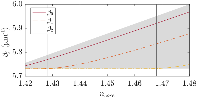
We see that the waveguides stop being bi-modal below and above as indicated by the vertical solid lines in Fig. 3. From the same figure, however, we also observe that for values around the propagation constants for both the TE and TE modes are nearly linear in , meaning that we can perform a linear fit for both in that region, while also maintaining only two supported modes in the waveguide. We obtain, for each mode :
| (11) |
with , , and . Each propagation constant has a different variation with respect to the refractive index, but from now on we will only focus on the TE mode.
We now consider the geometry showcased in Fig. 4, where we also display the refractive index modulation. The right waveguide features a constant core refractive index , while the refractive index of the left core is modulated following:
| (12) |
where . Although the same effect can be achieved by performing the modulation on the right waveguide, which would actually correspond more naturally with the Hamiltonian in (2), we choose to vary the left core for a direct comparison with the SUSY implementation described later. This Gaussian variation of the core index causes in turn a Gaussian change in the propagation constants through (11), and it is within current experimental reach [36]. and are parameters that determine the delay with respect to the coupling and the width of the Gaussian, respectively. We fix and choose so that the first level crossing occurs at , where the waveguides are closest and the coupling is maximal.
Both the coupling strength and the transfer efficiency are reduced as deviates from [34]. However, the relative variation for the coupling between the central value and the limits of the modulation has been computed to be below for the parameters considered in this work. As such, we can consider that the coupling does not deviate from the case of equal waveguides. In that case, the coupling strength between modes can simply be controlled by adjusting the distance between the waveguides, since the coupling decreases exponentially with their separation:
| (13) |
Knowing this, we perform a numerical study to determine the parameters and for the TE1 modes of identical waveguides with . The coupling strength for each distance can be gathered by means of the beat length:
| (14) |
which corresponds to the length at which complete light transfer occurs. By performing simulations at different distances and measuring the beat length we obtain the distribution in Fig. 5, from which we extract the following parameters: and .


For the geometry in Fig. 4, the coupling along approximately follows a Gaussian expression [22]:
| (15) |
whose width can be controlled through the curvature radius . In there, corresponds to the coupling at the point where the waveguides are closest, as computed from (13) for .
To describe the implementation of SUSY, let us come back to the situation depicted in Fig. 2. The propagation constants of the fundamental mode of the SUSY waveguide, TE, and the TE mode of the step-index waveguide will be equal, but the former will be much less extended into the cladding region than the latter. As such, compared to the coupling strength between the TE modes of two step-index waveguides, the coupling between SUSY and step-index waveguides will be weaker. To prove this, we measure the beat length between the TE and TE modes at different distances, and compute their coupling strength from (14). We plot the results in Fig. 5 and perform an exponential fit following Eq. (13), from which we can extract and . We denote the parameters with a tilde to indicate that they correspond to the coupling between the excited mode of the step-index waveguide and the fundamental mode of its superpartner profile.
To add SUSY to the SCRAP implementation, the most convenient method is to apply the modulation and the SUSY transformation to different waveguides. Hence, we substitute the right waveguide by its superpartner index profile, computed using the expression in (10) with a constant . This results in a refractive index profile at the input facet similar to the one shown in Fig. 2, but with the left core having an initial refractive index of . This core is then modulated along in the same way as in Fig. 4.
IV Results
We apply SCRAP combined with SUSY to efficiently transfer light intensity between multimode waveguides. First, in section IV.1 we exploit this efficient transfer to pump the excited mode of the step-index waveguide. The SUSY waveguide is single-mode, and as such its guided mode is easy to excite. This excitation can only be transferred to the TE mode due to the phase matching condition, thus achieving efficient pumping of this mode. To quantify the accuracy of the method, we define a fidelity:
| (16) |
which is an integral that compares the spatial profile of the output mode with the one of a particular target mode .
After that, we consider the demultiplexing possibilities of the method. We first consider the SCRAP technique without applying SUSY in section IV.2, and then comment on the improvement that SUSY brings in section IV.3. Since the light intensity of the TE mode is efficiently transferred between waveguides but the one for the TE is not, SCRAP allows to spatially separate a superposition of both. For this other application, we define the following figure of merit:
| (17) |
which is just the fraction of intensity of the TE mode that remains on the input waveguide multiplied by the fraction of intensity of the TE mode that gets transferred either to the other TE mode in section IV.2 or to the TE mode in section IV.3.
IV.1 Pumping of the TE mode
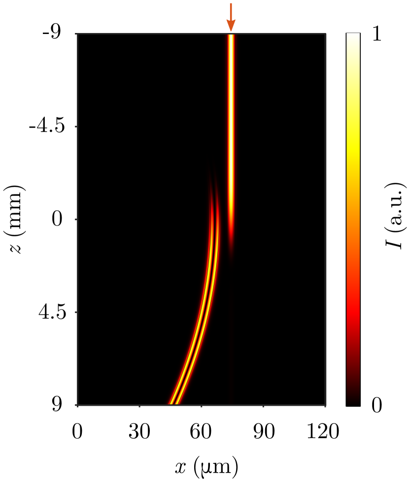
We perform finite difference numerical simulations to demonstrate that it is possible to efficiently pump the TE mode of the step-index waveguide starting from an excitation of the fundamental mode TE of the SUSY waveguide, which is now single-mode as depicted in Fig. 2. We show the light intensity propagation of this process in Fig. 6.
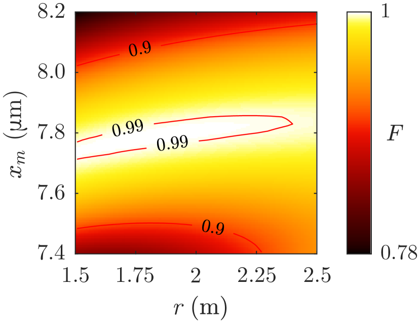
We compute the fidelity of the pumping according to (16), and show in Fig. 7 that we can obtain the target mode with fidelities above for a wide range of parameter values, with a significant region where fidelities exceed . Even if the geometrical parameters are slightly off and power transfer is not complete, light on the step-index waveguide will almost entirely be comprised by the TE mode. This results from the fact that despite their different spatial profiles, the SUSY fundamental mode can only be efficiently coupled to the TE mode of the step-index waveguide due to the phase-matching condition, and thus this procedure produces a negligible excitation of the TE mode. This can be proved by computing the overlap between the output field and the TE mode of the step-index waveguide, in the same way as in (16), which yields values below for all parameters considered in Fig. 7.
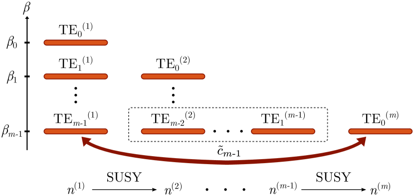
This scheme can also be applied to pump higher-order modes in higher-order multimode waveguides. We show a diagram of the effect of applying successive SUSY transformations to a -mode step-index waveguide in Fig. 8. One can couple the -mode waveguide to its superpartner after consecutive SUSY transformations, which is single mode. Modulating the core of the -mode waveguide allows to implement the SCRAP scheme between its TE mode, and the single mode of the SUSY waveguide. With this, one can pump the highest order mode of the original waveguide using a fundamental-mode input on its SUSY partner.
 \phantomcaption
\phantomcaption
\phantomcaption
\phantomcaption
\phantomcaption
\phantomcaption
\phantomcaption
\phantomcaption
\phantomcaption
IV.2 Mode demultiplexing
As previously mentioned, the SCRAP scheme allows to efficiently transfer light intensity to the TE mode between step-index waveguides, which can be exploited for mode demultiplexing even without applying SUSY. We first consider the geometry in Fig. 4 and perform numerical simulations for the propagation of the TE mode, the TE mode and an equally-weighted superposition of both. We display the results in Figs. 9, 9 and 9, respectively. From those figures, we can readily see that light in the TE mode is efficiently transferred, while the TE mode remains mostly confined in the left waveguide. The variation of the refractive index causes different mode levels to vary differently, see Fig. 3. Also, since the spatial profile of the TE mode is less extended into the cladding region compared to more excited states [34], the coupling between fundamental modes is weaker than that for the TE modes. Both these reasons cause the transmission for the TE mode to be less efficient when compared to the TE mode. Nonetheless, a small fraction of its power is still transferred, and that hinders the efficiency of the device as a demultiplexer. This can be seen most easily in Fig. 9, where the beating in intensity implies that the right waveguide holds a superposition of both TE modes, with a relative fraction that depends on the strength of the coupling for the TE mode.
 \phantomcaption
IV.3 SUSY-enhanced demultiplexing
Replacing the right waveguide with its SUSY partner entirely removes the possibility of coupling for the TE mode, since its equivalent on the SUSY waveguide is no longer supported, whilst maintaining the possibility of implementing the SCRAP efficiently for the TE mode.
We repeat the finite difference numerical simulations, and show the results of inputting the TE, TE and a superposition of both modes in Figs. 9, 9 and 9, respectively. In this case, light in the TE mode remains entirely confined in the left waveguide, while power is efficiently transferred between the TE and the TE of the SUSY partner waveguide. This has favorable implications in the efficiency, as shown in Fig. 10. The figure of merit given in Eq. (17) is overall larger for all parameter values, and reaches a maximum of for and a radius of curvature around .
However, the intensity profile of the TE mode is transformed into that of the fundamental mode of the right waveguide upon transfer, and is no longer antisymmetric. Introducing a superposition of modes into the device indeed leads to efficient mode separation but alters the intensity profile of the excited mode, causing the output to resemble the one from a beam splitter instead of the one from a traditional demultiplexer. In principle, adding a third bent waveguide on the right side should allow one to perform traditional demultiplexing [22] by implementing the three-state extension of the SCRAP method discussed in [14]. In that case, the spatial profile of the TE waveguide is recovered and the suppression of the transfer for the TE mode is maintained.
V Conclusions
In this work, we have described how we can implement SCRAP in a system of multimode waveguides by modulating the core refractive index of one of the waveguides, and further enhance its performance by applying a SUSY transformation to the refractive index profile of the other one. An excitation on the fundamental mode of the SUSY waveguide, single-mode, gets transferred and pumps the excited mode of the modulated step-index waveguide with very high efficiency, reaching fidelities above in a wide region of parameter values.
The SCRAP technique can also be exploited for mode demultiplexing in step-index multimode waveguides. The TE mode has a weaker coupling to the other waveguide than the exited mode, and light intensity on this mode remains mostly confined on the input waveguide, while light on the TE mode is efficiently transferred. One can exploit this to demultiplex a superposition of these modes, or to obtain an equally-weighted superposition from individual excitations on each mode by reversing the device. Computing the figure of merit for the demultiplexing process, we see that the method easily exceeds , but struggles to reach very high values. The efficiency of this process can be enhanced by substituting one of the waveguides by its SUSY partner. Unlike the previous case, the TE mode of the step-index waveguide is not supported by the SUSY one, implying that it cannot couple to it, while light in the TE mode can still be efficiently transferred into the SUSY fundamental mode by virtue of the SCRAP scheme. This allows for mode spatial separation with the figure of merit reaching , and overall with higher values than without SUSY, at the cost of altering the spatial profile of the transferred mode. Additionally, this method enables the possibility of turning fundamental-mode excitations on both waveguides into a superposition of fundamental and excited modes of the step-index waveguide.
The technological difficulty of implementing the SUSY refractive index profile can be lowered by considering a super-Gaussian profile for the initial waveguide, whose superpartners display much softer profiles than the ones for a step-index waveguide [37] while having a similar modal content. Higher-order superpartners allow to pump higher-order excited modes of the original waveguide, which are traditionally very challenging to excite precisely. The technique also goes beyond the context of optical waveguides. It would be of interest to extend the SCRAP implementation to different physical systems, as any system with multiple controllable energy levels can benefit from the technique.
Acknowledgements.
The authors acknowledge financial support from the Spanish Ministry of Science and Innovation MICINN (contracts no. FIS2017-86530-P and PID2020-118153GB-I00) and Generalitat de Catalunya (contract no. SGR2017-1646). We also thank Gerard Queraltó for helpful discussions.References
- [1] R. Olshansky. Propagation in glass optical waveguides. Reviews of Modern Physics, 51(2):341–367, apr 1979.
- [2] Erik Agrell, Magnus Karlsson, A. R. Chraplyvy, David J. Richardson, Peter M. Krummrich, Peter Winzer, Kim Roberts, Johannes Karl Fischer, Seb J. Savory, Benjamin J. Eggleton, Marco Secondini, Frank R. Kschischang, Andrew Lord, Josep Prat, Ioannis Tomkos, John E. Bowers, Sudha Srinivasan, Maïté Brandt-Pearce, and Nicolas Gisin. Roadmap of optical communications. Journal of Optics, 18(6):063002, jun 2016.
- [3] D. J. Richardson, J. M. Fini, and L. E. Nelson. Space-division multiplexing in optical fibres. Nature Photonics, 7(5):354–362, may 2013.
- [4] Chenlei Li, Dajian Liu, and Daoxin Dai. Multimode silicon photonics. Nanophotonics, 8(2):227–247, nov 2018.
- [5] Hongnan Xu, Daoxin Dai, and Yaocheng Shi. Silicon Integrated Nanophotonic Devices for On-Chip Multi-Mode Interconnects. Applied Sciences, 10(18):6365, sep 2020.
- [6] Yikai Su, Yu He, Haoshuo Chen, Xiaoying Li, and Guifang Li. Perspective on mode-division multiplexing. Applied Physics Letters, 118(20):200502, may 2021.
- [7] Peter J. Winzer. Making spatial multiplexing a reality. Nature Photonics, 8(5):345–348, may 2014.
- [8] Yousef Fazea and Vitaliy Mezhuyev. Selective mode excitation techniques for mode-division multiplexing: A critical review. Optical Fiber Technology, 45:280–288, nov 2018.
- [9] D. J. Richardson. New optical fibres for high-capacity optical communications. Philosophical Transactions of the Royal Society A: Mathematical, Physical and Engineering Sciences, 374(2062):20140441, mar 2016.
- [10] L. P. Yatsenko, B. W. Shore, T. Halfmann, K. Bergmann, and A. Vardi. Source of metastable H(2 s ) atoms using the Stark chirped rapid-adiabatic-passage technique. Physical Review A, 60(6):R4237–R4240, dec 1999.
- [11] T. Rickes, L. P. Yatsenko, S. Steuerwald, T. Halfmann, B. W. Shore, N. V. Vitanov, and K. Bergmann. Efficient adiabatic population transfer by two-photon excitation assisted by a laser-induced Stark shift. The Journal of Chemical Physics, 113(2):534–546, jul 2000.
- [12] S.A. Myslivets, A.K. Popov, T. Halfmann, J.P. Marangos, and Thomas F. George. Nonlinear-optical vacuum ultraviolet generation at maximum atomic coherence controlled by a laser-induced Stark chirp of two-photon resonance. Optics Communications, 209(4-6):335–347, aug 2002.
- [13] T. Rickes, J.P. Marangos, and T. Halfmann. Enhancement of third-harmonic generation by Stark-chirped rapid adiabatic passage. Optics Communications, 227(1-3):133–142, nov 2003.
- [14] A A Rangelov, N V Vitanov, L P Yatsenko, B W Shore, T Halfmann, and K Bergmann. Stark-shift-chirped rapid-adiabatic-passage technique among three states. Physical Review A, 72(5):053403, nov 2005.
- [15] Bo Y. Chang, Hyeonho Choi, Seokmin Shin, and Ignacio R. Sola. Quantum-state-selective two-photon excitation of multilevel systems assisted by the Stark shift. Physical Review A, 75(6):063405, jun 2007.
- [16] Martin Oberst, Holger Münch, and Thomas Halfmann. Efficient Coherent Population Transfer among Three States in NO Molecules by Stark-Chirped Rapid Adiabatic Passage. Physical Review Letters, 99(17):173001, oct 2007.
- [17] N. Shirkhanghah, M. Saadati-Niari, and S. Ahadpour. Fractional population transfer among three-level systems in a cavity by Stark-shift-chirped rapid adiabatic passage. Quantum Information Processing, 19(4):128, apr 2020.
- [18] Mohammad-Ali Miri, Matthias Heinrich, Ramy El-Ganainy, and Demetrios N Christodoulides. Supersymmetric Optical Structures. Phys. Rev. Lett., 110(23):233902, jun 2013.
- [19] Mohammad-Ali Miri, Matthias Heinrich, and Demetrios N Christodoulides. Supersymmetry-generated complex optical potentials with real spectra. Phys. Rev. A, 87(4):43819, 2013.
- [20] Matthias Heinrich, Mohammad-Ali Miri, Simon Stützer, Ramy El-Ganainy, Stefan Nolte, Alexander Szameit, and Demetrios N Christodoulides. Supersymmetric mode converters. Nature Communications, 5(1), 2014.
- [21] Maria Principe, Giuseppe Castaldi, Marco Consales, Andrea Cusano, and Vincenzo Galdi. Supersymmetry-Inspired Non-Hermitian Optical Couplers. Scientific Reports, 5(1), feb 2015.
- [22] Gerard Queraltó, Verònica Ahufinger, and Jordi Mompart. Mode-division (de)multiplexing using adiabatic passage and supersymmetric waveguides. Opt. Express, 25(22):27396–27404, oct 2017.
- [23] Andrés Macho, Roberto Llorente, and Carlos García-Meca. Supersymmetric Transformations in Optical Fibers. Phys. Rev. Applied, 9(1):14024, 2018.
- [24] Gerard Queraltó, Verònica Ahufinger, and Jordi Mompart. Integrated photonic devices based on adiabatic transitions between supersymmetric structures. Opt. Express, 26(26):33797–33806, 2018.
- [25] Wiktor Walasik, Bikashkali Midya, Liang Feng, and Natalia M Litchinitser. Supersymmetry-guided method for mode selection and optimization in coupled systems. Opt. Lett., 43(15):3758–3761, 2018.
- [26] A Contreras-Astorga and V Jakubský. Photonic systems with two-dimensional landscapes of complex refractive index via time-dependent supersymmetry. Phys. Rev. A, 99(5):53812, may 2019.
- [27] Stefano Longhi. Invisibility in non-Hermitian tight-binding lattices. Phys. Rev. A, 82(3):32111, sep 2010.
- [28] Matthias Heinrich, Mohammad-Ali Miri, Simon Stützer, Stefan Nolte, Demetrios N Christodoulides, and Alexander Szameit. Observation of supersymmetric scattering in photonic lattices. Opt. Lett., 39(21):6130–6133, nov 2014.
- [29] Mohammad-Ali Miri, Matthias Heinrich, and Demetrios N Christodoulides. SUSY-inspired one-dimensional transformation optics. Optica, 1(2):89–95, 2014.
- [30] Stefano Longhi. Supersymmetric transparent optical intersections. Opt. Lett., 40(4):463–466, feb 2015.
- [31] Carlos García-Meca, Andrés Macho Ortiz, and Roberto Llorente Sáez. Supersymmetry in the time domain and its applications in optics. Nature Communications, 11(1), feb 2020.
- [32] Gerard Queraltó, Mark Kremer, Lucas J Maczewsky, Matthias Heinrich, Jordi Mompart, Verònica Ahufinger, and Alexander Szameit. Topological state engineering via supersymmetric transformations. Communications Physics, 3:49, mar 2020.
- [33] Fred Cooper, Avinash Khare, and Uday Sukhatme. Supersymmetry and quantum mechanics. Physics Reports, 251(5):267–385, 1995.
- [34] Bahaa E A Saleh and Malvin Carl Teich. Fundamentals of photonics. Wiley-Interscience, 2nd edition, 2007.
- [35] Alexander Szameit, Felix Dreisow, Thomas Pertsch, Stefan Nolte, and Andreas Tünnermann. Control of directional evanescent coupling in fs laser written waveguides. Opt. Express, 15(4):1579–1587, feb 2007.
- [36] Alexander Szameit and Stefan Nolte. Discrete optics in femtosecond-laser-written photonic structures. Journal of Physics B: Atomic, Molecular and Optical Physics, 43(16):163001, jul 2010.
- [37] Mohammad-Ali Miri, Matthias Heinrich, and Demetrios N. Christodoulides. Supersymmetric optical waveguides. In Physics and Simulation of Optoelectronic Devices XXII, volume 8980, 2014.