huyanchao@cardc.cn ]
yangyanguang@cardc.cn ]
Hypersonic curved compression ramp flows with bistable states
Abstract
The bistable states and separation hysteresis in curved compression ramp (CCR) flows, and the corresponding aerothermal characteristics (including wall friction , pressure and heat flux ), are studied numerically and theoretically. Direct numerical simulations of separation hysteresis induced by variation of turning angle , as well as the influence of inflow Mach number and wall temperature on hysteresis loops, are carried out. Distributions of wall friction, pressure and heat flux are analyzed. Further, emergence of ’s first and second minima in the separation bubble is interpreted, revealing it is dominated by the adverse pressure gradient (APG) induced by separation and reattachment shocks. The present results and analysis indicate that the reversed-flow singularity of Smith (Proceedings of the Royal Society of London. A. Mathematical and Physical Sciences, 1988, 420: 21-52) is less likely to occur in CCR flows. The prediction of peak pressure of separation states confirms the model based on the minimum viscous dissipation theorem (Physics of Fluids, 2020, 32(10):101702). While the pressure overshoot can be analyzed by shock-polars with pressure match of compression and expansion process. The correlation between peak heat flux and peak pressure rise of both separation and attachment states is also discussed in terms of the classical power relations.
I Introduction
Deflection of control surface such as body flaps, elevons and rudders may cause intense shock wave/boundary layer interaction (SBLI). SBLI may yield significant flow separation and lead to significant decrease in control effectiveness and the excessive increase of the heat flux, and even lose control of aircraftSimeonides, Haase, and Manna (1994); Simeonides and Haase (1995); Babinsky and Harvey (2014); Zhang (2020). During this process, the flow hysteresis may be encountered, which can lead to multistable systems manifested as the dependence of a system on its evolutionary history, and ubiquitous in aerospace flow systemsHu et al. (2020a). Hysteresis can lead to multiple values of aerodynamic coefficients such as lift and drag in the hysteresis loopYang et al. (2008); McCroskey (1982); Mueller (1985); Biber and Zumwalt (1993); Mittal and Saxena (2000). The hysteresis of the regular and Mach reflection is found when changing the incident angle of the shockHornung, Oertel, and Sandeman (1979); Chpoun et al. (1995); Vuillon, Zeitoun, and Ben-Dor (1995); Chpoun and Ben-Dor (1995); Ivanov et al. (2001), and the mechanism is explained by Hu et al. with minimal dissipation theoryHu et al. (2021). Recently, a separation/attachment hysteresis in curved compression ramp (CCR) flows induced by variation of attack angle is observed via numerical simulationHu et al. (2020a). Mechanism of separation hysteresis in CCR flows is discussed by Zhou et alZhou et al. (2021).
As a classic configuration of SBLI, compression ramp flow has been much studiedBabinsky and Harvey (2014). The free interaction theory Chapman, Kuehn, and Larson (1958); Erdos and Pallone (1962) (FIT) established by Chapman et al. argues that the supersonic flow is influenced by the local boundary layer and the inviscid contiguous stream rather than the further development of the interaction. The triple deck theory formulated by Stewartson & WilliamsStewartson and Williams (1969) and NeilandNeiland (1973) provides the characteristic scale of each region and a series of equations to solve the exact physical quantities. By analytically deducing and numerically solving the triple deck equation, SmithSmith (1988), Smith & KhorramiSmith and Khorrami (1991) found that when the turning angle of the compression ramp is large enough, the separation bubble will become unstable and break down, and a singularity may arise within the reversed-flow region when the turning angle reaches a critical value. Korolev et al.Korolev, Gajjar, and Ruban (2002), Logue et al.Logue, Gajjar, and Ruban (2014) and Gai & KhraibutGai and Khraibut (2019) confirmed the separation bubble will become unstable and break down, but they did not encounter singularity.
The peak heat flux in the reattachment region is an important feature of separated flow. Most empirical methods to predict the peak heat flux always correlate it with peak pressure riseSimeonides, Haase, and Manna (1994); Simeonides and Haase (1995); Holden (1978); Hung and Barnett (1973); Hung (1973). Studies on wall pressure distributions are abundant. Theoretical predition mothed for pressure distribution of incipiently separated or just past incipient separation flows is proposed by Stollery & BateStollery and Bates (1974), which is not applicable for well separated flows. For well separated flow, FIT can predict the pressure rise at separation point and the plateau Chapman, Kuehn, and Larson (1958). However, the peak pressure can not be predicted by FIT. Some semi-empirical expressions for plateau and peak pressure under certain conditions have been establishedGumand (1959). Rencently, Hu et al. proposed an implicit model based on the minimum viscous dissipation (MVD) theorem for prediction of plateau and peak pressure of compression ramp flows with large separated regionsHu et al. (2020b). Li proposed an explicit theretical model combining FIT to predict plateau and peak pressure, which is validated at low-to-medium Reynolds numberLi, Yu, and Bao (2021).
Herein, separation hysteresis of CCR flows induced by the variation of turning angle is studied with two-dimensional (2D) numerical simulations. The hysteresis loops and the corresponding wall quantities are analyzed in the second section, as well as the influence of the inflow Mach number and wall temperature. In the third section, we discuss the aerothermal characteristics of the hysteresis process in detail.
II Results
II.1 The hysteresis loops induced by turning angle -variation
Direct numerical simulations (DNS) of 2D CCR flow based on OpenCFDLi et al. (2010) are carried out in the present research. The flat plate starts at . The turning angle ranges from to , and the curved wall is an arc with the curvature radius , where with being the starting point of the curved wall. The unit Reynolds number () of the flow is , , the specific heat ratio , the inflow Mach number , and the normalized wall temperature (, where is the inflow temperature). Simulations are also carried out with inflow and boundary conditions (IBCs) of () and (). Other flow settings are consistent with Ref.Hu et al. (2020a) and numerical validations have been provided in Refs.Hu et al. (2020a); Li et al. (2010).
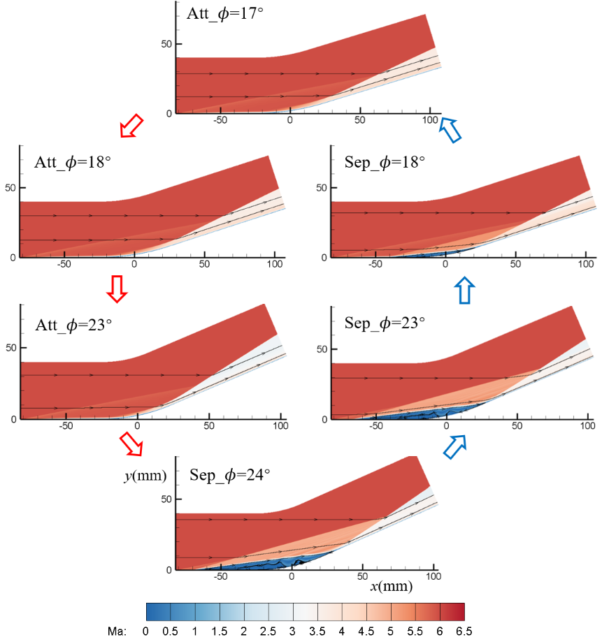
Fig.1(a) shows the separation/attachment hysteresis loop induced by -variation, with IBCs of (). A steady attachment flow is organized when . And the attachment state maintains till in the process that increases with gradually after the flow reaches convergence (state Att_ to Att_ in Fig.1(a)). When reaches , the flow will suddenly separate. When decreases from with the same after the flow reaches a steady state, the flow maintains separation till reaches , at which angle the separation will disappear and the flow reaches attachment state again. When ( and for the current IBCs), the flow states may be either separated or attached with the same IBCs, depending on different initial conditions.
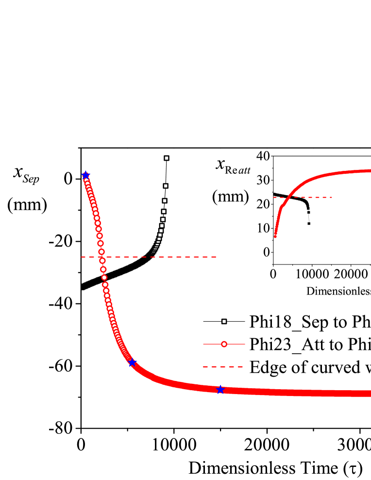
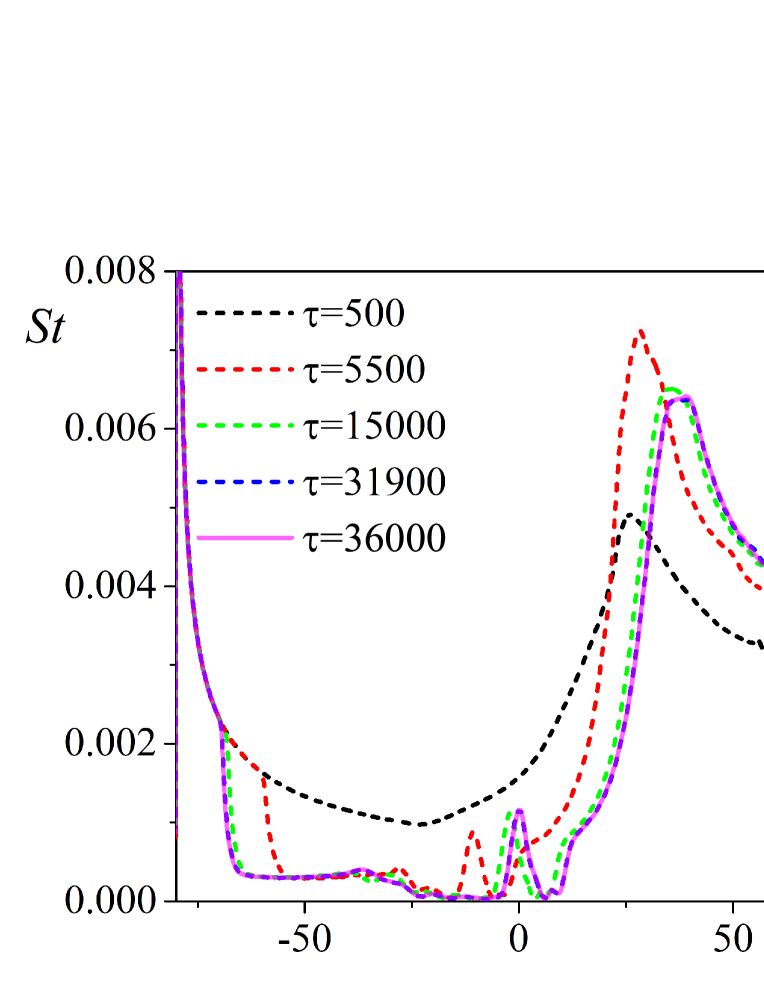
Locations of separation/reattachment points and distributions of Stanton number are monitored to determine
convergence, and their values during the process from separation to attachment (Phi18_Sep to Phi17) and from attachment to separation (Phi23_Att to Phi24) are depicted in Fig.2(a) and Fig.2(b). The Stanton number is
| (1) |
where is the wall heat flux, , and the inflow density and velocity. For the separation states, the flow is said to be in convergence when the displacements of separation point and the location of peak heat flux are less than in . (Dimensionless time corresponds to ) , and the flow passes through in .) An interesting phenomenon is that separation/reattachment points will not lie on the curved wall after convergence in separation states.
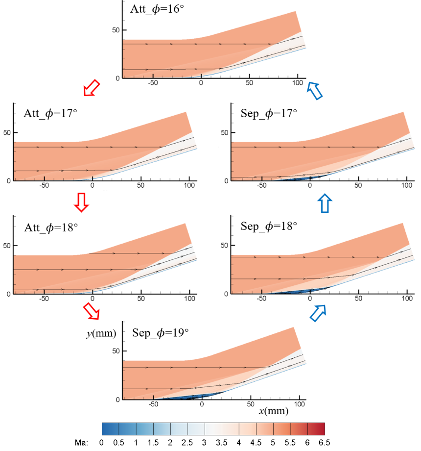
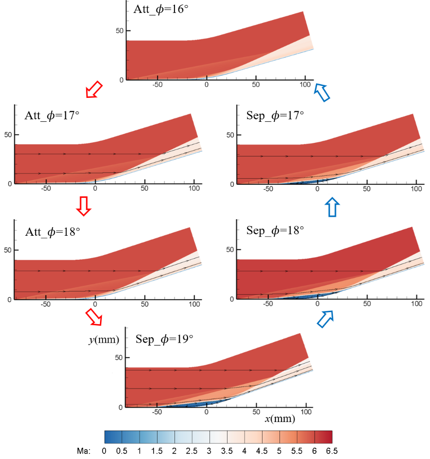
Similar hysteresis processes are observed with IBCs () and (), as shown in Fig.1(b) and Fig.1(c). But the interval is shifted and narrowed to for the two cases. Decrease of or increase of results in decrease of maximum APG the boundary layer can resistZhou et al. (2021). Therefore separation will appear at a smaller .
The closed separation/attachment hysteresis loop is composed of three parameter intervals of turning angle with certain , and , i.e., overall separation interval (OSI) in which the flow can only be in separation state; overall attachment interval (OAI) in which the flow can only be in attachment state; dual-solution interval (DSI) in which both steady attachment and separation states could exist. Decreasing or increasing will shift and reduce the DSI .
II.2 Distributions of , and
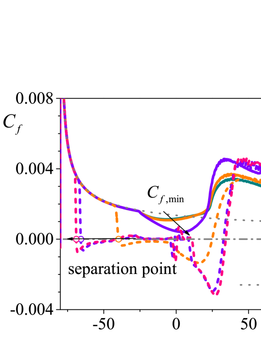
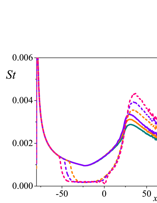
Distributions of wall friction with different are shown in Fig.3(a), Fig.3(d) and Fig.3(g) for different and conditions, where and is the wall shear stress. For attachment states, the non-monotonic distributions of on the curved wall result from the compression and APG effects simultaneously. The minimum of decreases with the increase of , indicating a tendency to separate. For separation states, the separation point moves upstream with increasing , to obtain higher wall friction to balance APG, corresponding to a larger separation bubble. Due to the breakdown of vortices, fluctuations of arise near for and . In the downstream of curved wall, reaches maximum, and then decreases with streamwise development in both separation and attachment states.
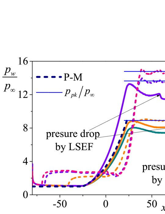
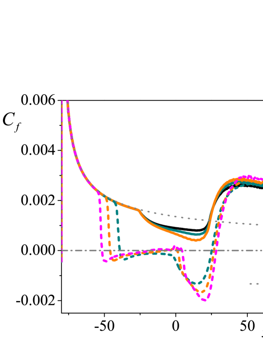
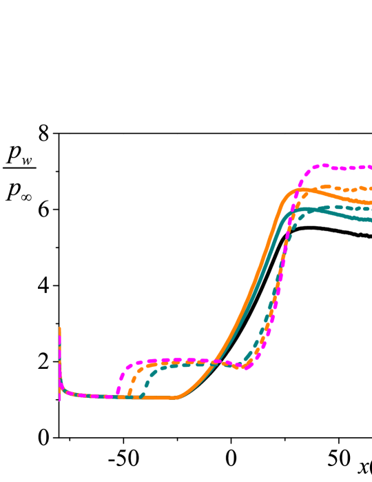
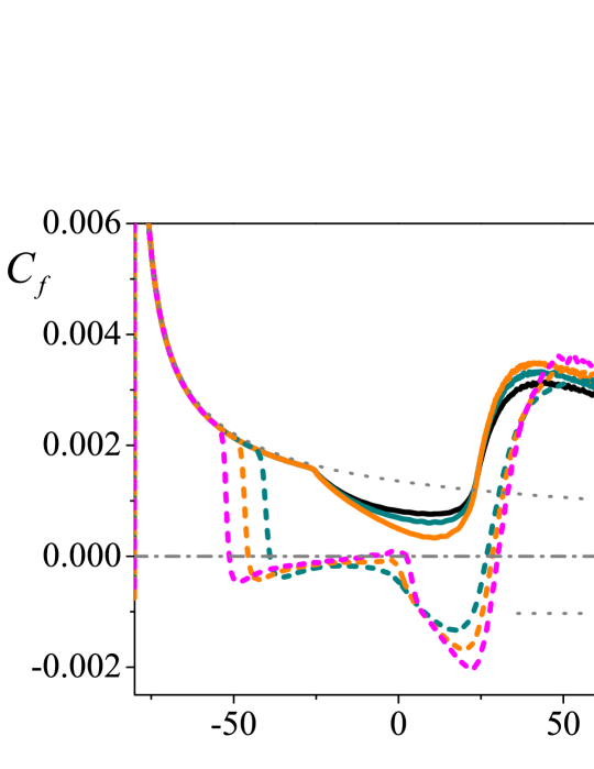
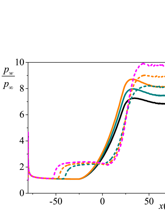
The wall pressure distributions are shown in Fig.3(b), Fig.3(e) and Fig.3(h), where is the inflow pressure. The attachment states sustain approximate isentropic compression process induced by the curve wall. As shown by the navy dash line in Fig.3(b), the process can be described by Prandtl-Meyer relation
| (2) |
where is the turning angle at
| (3) |
In the separation states, a pressure plateau arises at the separation region and sustain a second pressure rise to reach the pressure peak after reattaching.
In the downstream of the curved wall, drops twice in attachment states or separation states with small . The resultant favourable pressure gradient results in local maximum . The second drop is due to the expansion fan induced by the leading edge (LE) shock (LESF), but the first drop results from different mechanism. For the attachment states, it is due to the pressure match of isentropic compression and pressure rise by the shock, which leads to an overshoot and will be discussed in the following. For the separation states, the expansion fan induced by separation shock (SSEF) is the major reason. Separation states with large encounter one pressure drop due to SSEF. After these processes, reaches the inviscid pressure rise.
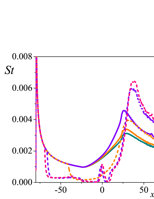
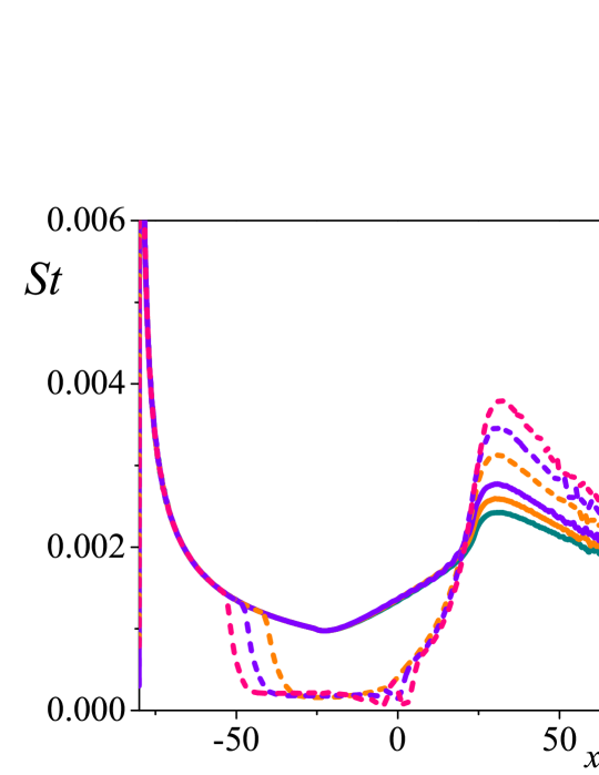
The Stanton number distributions are shown in Fig.3(c), Fig.3(f) and Fig.3(i). In attachment states, the heat fluxes increase along the curve wall and reach the peak values near its end. In separation states, the heat flux is close to zero (the fluctuations near are due to the breakdown of vortices) inside the separation bubble, and the peak heat fluxes occur nearby the boundary layer reattaching. Compared with the separation states, the peak heat fluxes of the attachment states are lower with the same IBCs and , and the discrepancy increases with larger (up to 32% in present cases).
As shown in the distributions of , and , the attachment and separation states with the same IBCs correspond to vastly different aerothermal manifestation.
III Discussion
III.1 Wall shear stress in the reversed-flow region
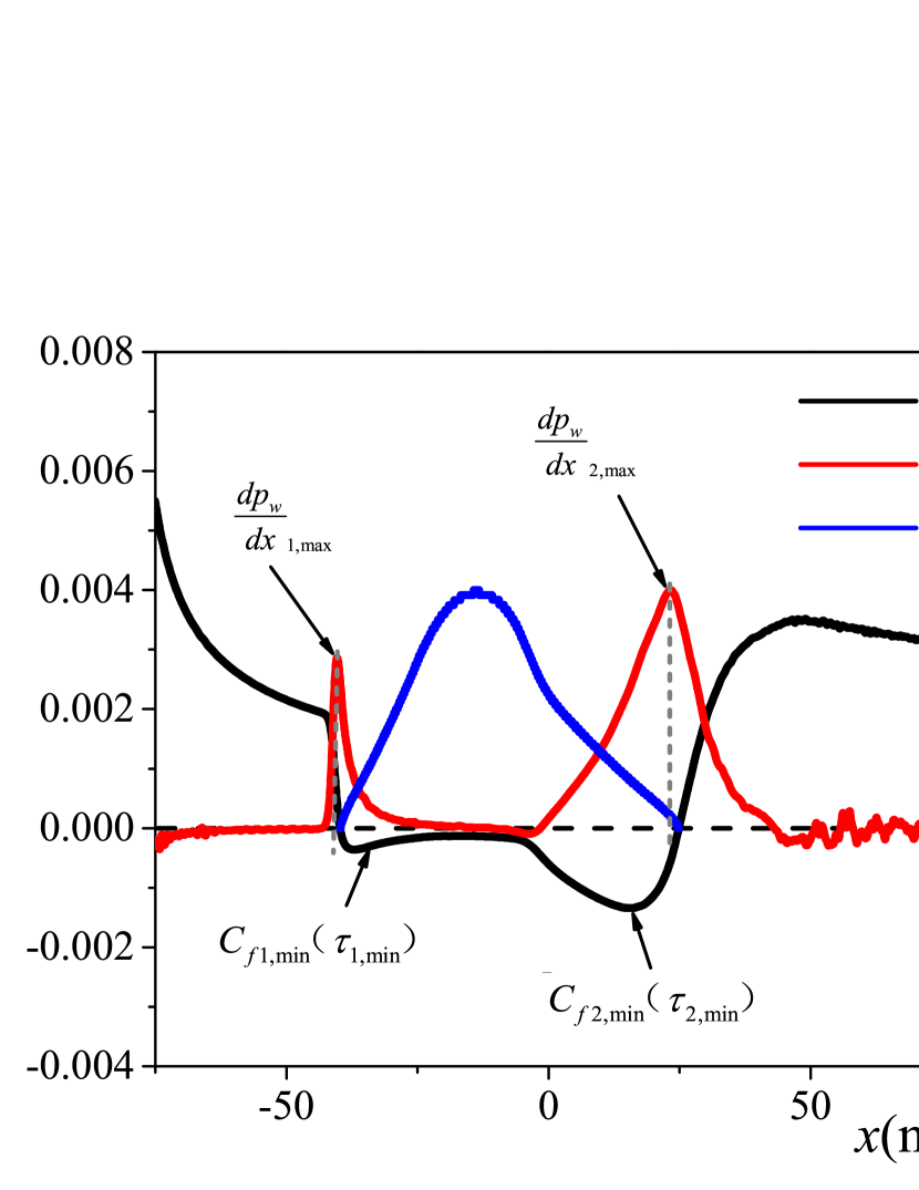
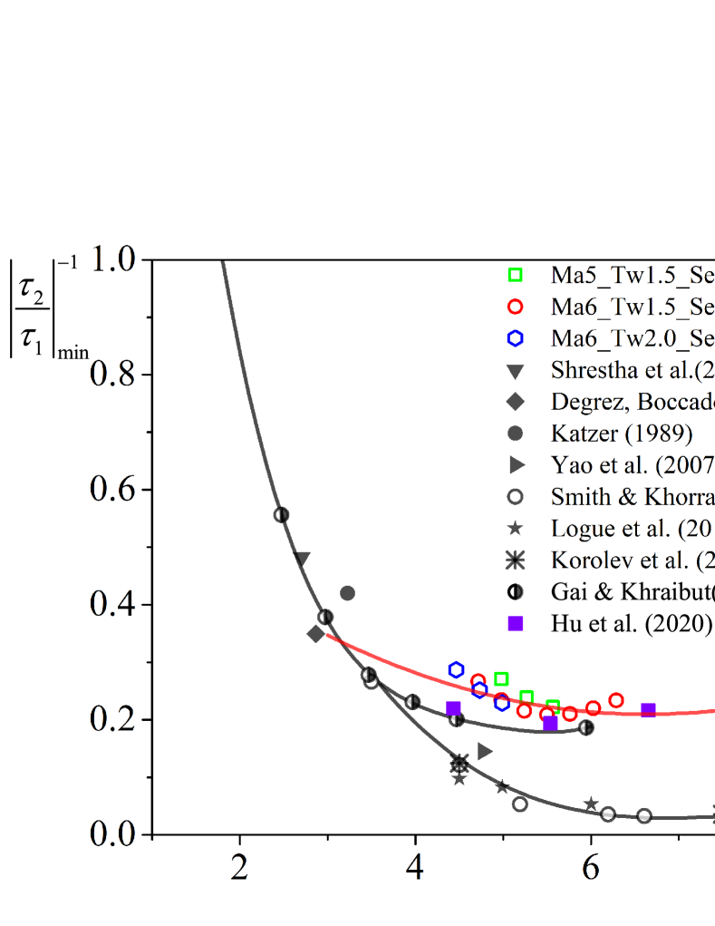
The appearance of the second minimum shear stress immediately before reattachment is a characteristic feature of compression ramp flows with large separation (CRFLS). Such phenomenon also exists in CCR flows with separation, as shown in Fig.4. As a measure of the extent of separation, the scaled angle is definedStewartson (1970) as , where is the geometric turning angle. is the characteristic Reynolds number based on the flat plate length and the free-stream conditions. is the Chapman–Rubesin parameter and is the shear constant of a Blasius boundary layer.
SmithSmith (1988) and Smith & KhorramiSmith and Khorrami (1991) suggested that results from unstableness or breakdown of the separation bubble. KatzerKatzer (1989) suggested it is the displacement of the separation bubble center that generates . But they did not offer correlations of with other flow parameters. SmithSmith (1988) and Smith & KhorramiSmith and Khorrami (1991) also suggested that when is large enough, a singularity may arise with . Based on Neiland’s reattachment theoryNeiland (1973), Korolev et al.Korolev, Gajjar, and Ruban (2002) verified when , but they did not encounter singular for up to 7.5. Gai & KhraibutGai and Khraibut (2019) suggested that is less likely to occur for low wall temperature ratio. Fig.5 shows the distributions of (including the early literatureSmits and Dussauge (1996); Korolev, Gajjar, and Ruban (2002); Logue, Gajjar, and Ruban (2014); Gai and Khraibut (2019); Hu et al. (2020b); Shrestha et al. (2016); Degrez, Boccadoro, and Wendt (1987); Katzer (1989); Yao et al. (2007)) with variation of . For the present cases, distribution of is similar with the results of Gai & KhraibutGai and Khraibut (2019) and Hu et al.Hu et al. (2020b). And seems to increase slowly when in the present cases and the results Hu et al.Hu et al. (2020b).
In CCR flows, can appear without separation bubble breakdown. Here, a theoretical interpretation of and is proposed as follows. The tangential momentum equation in orthogonal curvilinear coordinatesSchlichting and Gersten (2017) is incorporated as
| (4) |
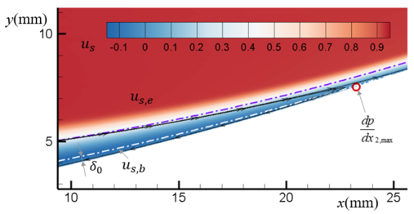
where and is the wall surface curvature. We carry out the analysis in the region between the wall and zero shear stress line (ZSSL, white dash-dot line in Fig.6), where the shear stress is equal to 0 in the separation bubble. As shown in Fig.6, the velocity between the white dash-dot line and the wall is small compared with the eternal flow velocity , fulfilling . Then, Eq.4 to describe the region we focus on can be simplified as
| (5) |
Integrating Eq.5 from the wall to ZSSL along the normal direction , with the assumption that the pressure is constant across the boundary layer, we can obtain
| (6) |
In the formula, the characteristic thickness corresponds to the normal distance from the wall to ZSSL, and is the shear stress on ZSSL. Besides, , then . Combining the definition of , Eq.6 can be deduced and rearranged as
| (7) |
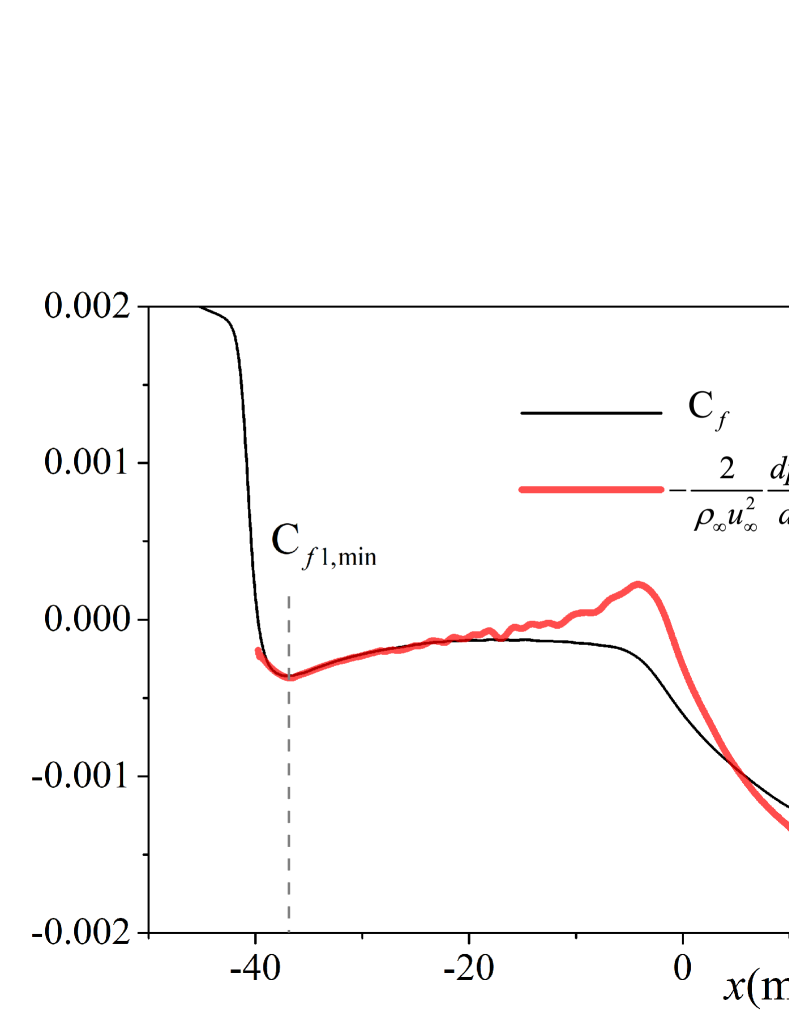
From Eq.7, the wall friction is proportional to the product of APG and . From Fig.4 we can see that two local maximal APGs arise near separation and reattachment points, which are induced by separation and reattachment shocks, respectively. While is equal to 0 at separation and reattachment points, and have a maximum in the separation bubble. The location of maximum does not lie in the middle of separation and reattachment points(Fig.4), nor does present symmetric distribution, both manifesting the displacement of the separation bubble, as observed by KatzerKatzer (1989). The product of APG and results in two peak values, corresponding to the first and second minimum values of wall friction, i.e. and . Therefore, the essential condition for the emergence of may not be the unstableness or breakdown of separation bubble, but the explicit separation and reattachment shocks, which can also observed in the present case. Validation of Eq.7 is depicted in Fig.7. Both the values and locations of and fit well, and the discrepancy of value is within 13%. Moreover, as when approaching separation/reattachement point, the simplification from Eq.4 to Eq.5 is closer to the real conditions, and better agreements can be obtained.
From the perspective of the flow field, the sonic line of the separation state (purple dash-dot line in Fig.6, where the shock is transferred to a series of compression waves, lies at a certain height from the wall. Therefore the wall pressure gradient is hardly approaching infinity. Combining Eq.7, and singularity in the reversed-flow region is less likely to exist in CCR flows.
III.2 Peak pressure rise and heat flux
As discussed above, separation hysteresis results in quite different pressure and heat behavior. Herein, we further discuss the peak pressure rise and peak heat flux in the hysteresis process.
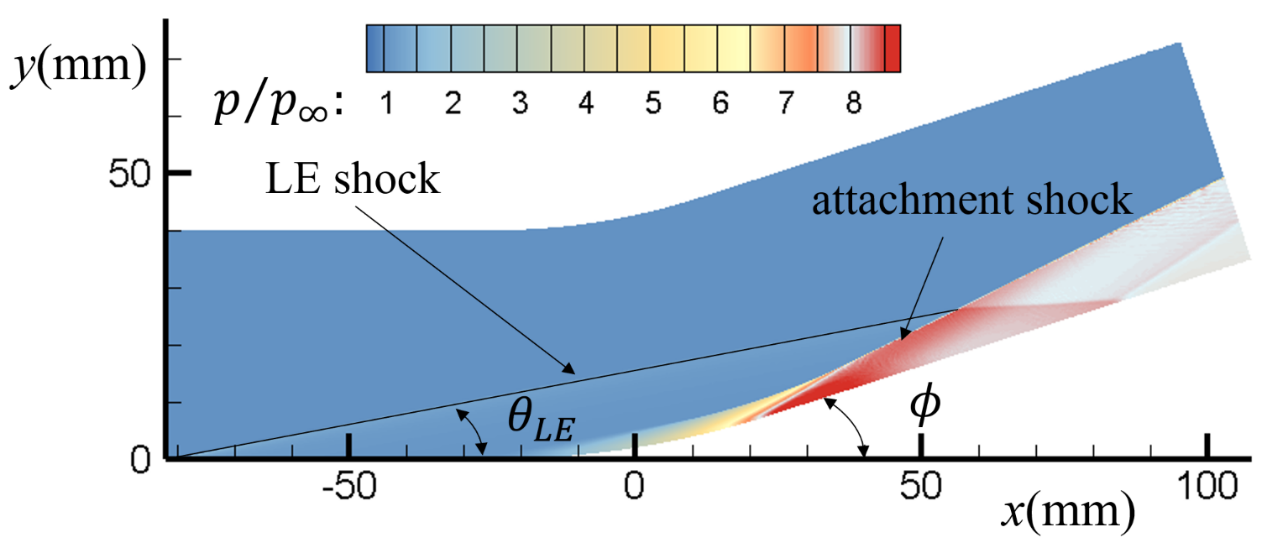
For the attachment states, the characteristic pressure can be analyzed by shock-polars and Prandtl-Meyer relation (Fig.8). It is noted that knowledge of the deflection angle (Fig.8(b)) that induces the LE shock is required. And is obtained by the post LE shock pressure rise in the present analysis. The pressure presents an overshoot , which is a result of the pressure match between isentropic compression on the curved wall and the pressure rise by the attachment shock. The pressure match process is implemented by the expansion waves which originate from the reflection of the compression waves on the attachment shock. Good agreement of between DNS results and the results based on the match of compression and expansion process (MCEP) is obtained, as shown in Fig.8(c) and Fig.9 (denoted as ). The post-shock pressure rise (the pressure after attachement shock in Fig.8(b)) and inviscid pressure rise calculated by shock-polars are also consistent with the DNS results.
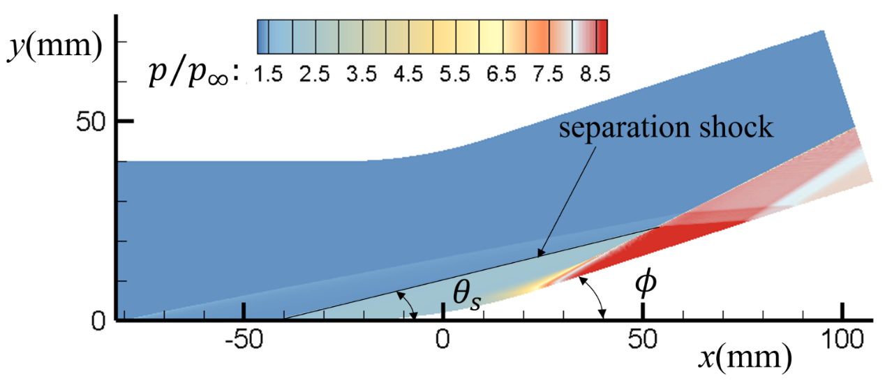

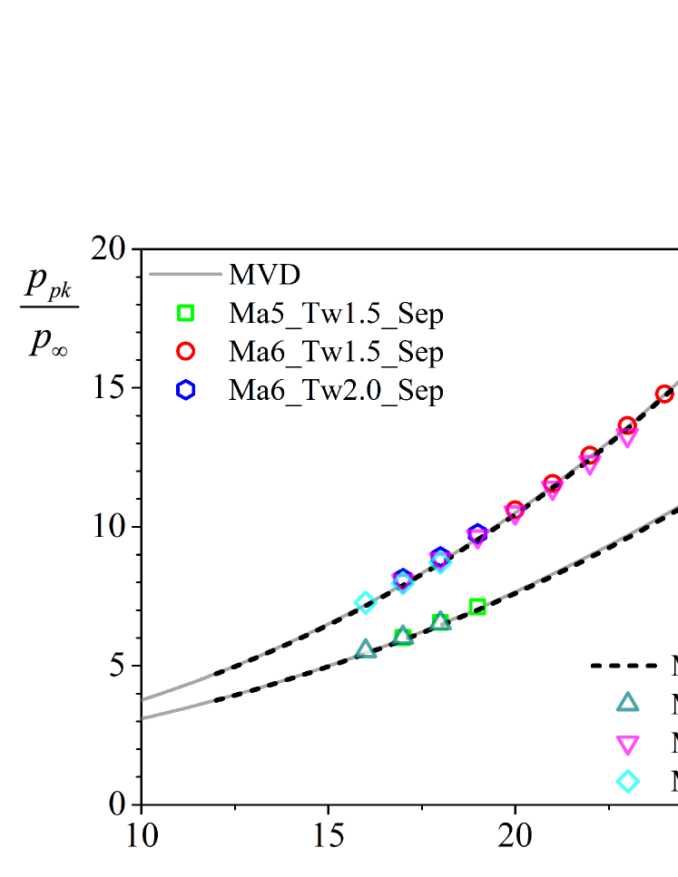
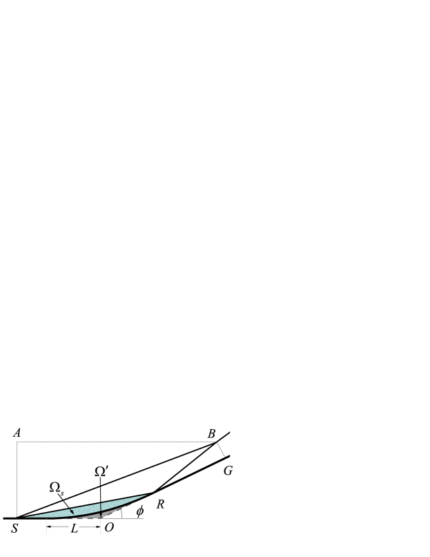
Using minimum viscous dissipation (MVD) theorem, Hu et al.Hu et al. (2020b) have predicted the peak pressure in CRFLS and obtained good agreement with the numerical and experimental results. As the separation states of CCR have similar shock structure to CRFLS’s (Fig.10), the total dissipation in the control volume that consists of SA, AB, BG and the wall is still primarily contributed by separation and reattachment shocks and , i.e.
| (8) |
where and are the lengths of separation/reattachment shocks and , respectively. denotes the dissipation induced by a shock per unit length. Furthermore, the assumption in Ref.Hu et al. (2020b) that the fluid mass in the separation bubble is proportional to the pressure rise in the plateau region is still adopted. As is proportional to , the same inference can be drawn that the area of the separation bubble is assumed to be constant for given and . Besides, as is constant for given , the area of triangle is derived to be constant. Therefore the corresponding model in Ref.Hu et al. (2020b) is applicable to the CCR flow with large separation.
The comparison between predicted by MVD and the results of DNS is shown in Figs.8(c) and Fig.9. Here the deflection angle in Fig.8(a) and Fig.8(c) that induces the separation shock is also predicted by MVD. We can see that the predicted results are in good agreement with the DNS results for the IBCs selected in this paper. Moreover, hardly influence , indicating that the change of has little influence on shock structures in a certain range. The good predictions of peak pressure provide a good basis for predicting peak heat flux in attachment and separation states.
Additionally, an interesting phenomenon can be found in Fig.9. The results of MVD and MCEP overlap well, which means nearly the same peak pressure can be obtained for separation state and attachment state with the same and IBCs. Such phenomenon may indicate the separation bubble shape and the resultant shock structure of separation states result in the minimum visous dissipation to nearly isentropic compression process in the attachment states.
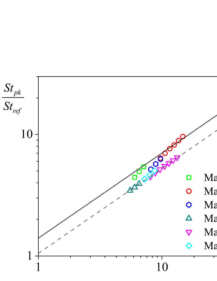
Thermal protection design requires the severe peak heat flux in the reattachment region of separation states. There are several methods for predicting the peak heat fluxSimeonides, Haase, and Manna (1994); Simeonides and Haase (1995); Holden (1978); Marini (2001); Li, Bao, and Tong (2012); Currao et al. (2020); Hung and Barnett (1973); Hung (1973), and the peak heat flux is generally correlated with peak pressure rise in these methods. One simple correlation is expressed in the following formHung and Barnett (1973); Hung (1973)
| (9) |
where
| (10a) | ||||
| (10b) | ||||
The refers to Eckert’s reference temperature methodEckert (1960), and is the location of the peak heat flux. As shown in Fig.11, the separation and attachment states both satisfy Eq.9, and the exponent are indicated by the tendency. The exponent is in accordance with the laminar/laminar interference of HungHung (1973), while the coefficient . The discrepancy of coefficient may result from the lower estimate of by Eckert’s methodEckert (1960) than measured values, which can be found in Ref.Hung (1973). Larger coefficient of separation states indicates higher peak heat fluxes than that of the attachment states with the same pressure rise. This indicates that it is promising to reduce a mass of heat flux by adjusting or other methods to keep the flow attached in the DSI.
IV Conclusion
In this paper, separation hysteresis in CCR flow induced by variation of turning angle , as well as the corresponding aerothermal characteristics, is investigated. In the interval (), the boundary layer in CCR flow can be stably in either attachment or separation state with the same IBCs, and the state is determined by the evolutionary history of -variation. This interval is the dual-solution interval (DSI). And DSI is shifted and narrowed with the decrease of or the increase of . For the turning angle outside DSI, only one stable state exists, either attachment or separation. In DSI, the separation and attachment states lead to a great difference in aerothermal features. The pressure rise process in the attachment state is approximately isentropic process, and the peak heat flux from separation state to attachment state can be reduced by up to 32% within the present cases.
The relationship between the second minimum shear stress and the scaled angle of the separation states is analyzed. The results indicate that with the increase of , is less likely to reach infinite value for low wall temperature ratio, confirming Gai’s suggestionGai and Khraibut (2019). Besides, the emergence of and is interpreted with simplified momentum equation, correlated with APG and characteristic thickness between the wall and the zero shear stress line. The correlation is validated with good agreement, indicating and are dominated by APG induced by separation and reattachment shocks. Results and theoretical analysis indicate that the singularity in the reverse-flow singularities pointed out by SmithSmith (1988) is less likely to appear in CCR flow.
Peak pressure and peak heat flux emerged in the process of separation hysteresis are analyzed. Good prediction of the pressure peak of separation states is obtained with MVDHu et al. (2020b), since the shock structure of CCR separation state is similar with CRFLS. And the pressure rise by separation and reattachment shocks in the separation states is close to that of attachment states by isentropic process for the same , indicating the separation bubble shape and the resultant shock structure indeed results in the minimum viscous dissipation. The relationship between peak heat flux and peak pressure rise fulfills the classical power relations, but the peak heat flux in the separation state is significantly higher than that in the attachment state, indicating that maintaining the attachment state in DSI by means of adjustment is of great significance to reduce the heat flux.
Acknowledgements.
We are grateful to professor Xin-Liang Li for his helpful discussions. This work was supported by the National Key R & D Program of China (Grant No. 2019YFA0405300). Yan-Chao Hu thanks to the support of the China Postdoctoral Science Foundation (Grant No. 2020M683746).reference
References
- Simeonides, Haase, and Manna (1994) G. Simeonides, W. Haase, and M. Manna, “Experimental, analytical, and computational methods applied to hypersonic compression ramp flows,” AIAA Journal 32, 301–310 (1994).
- Simeonides and Haase (1995) G. Simeonides and W. Haase, “Experimental and computational investigations of hypersonic flow about compression ramps,” Journal of Fluid Mechanics 283, 17–42 (1995).
- Babinsky and Harvey (2014) H. Babinsky and J. K. Harvey, Shock Wave-Boundary-Layer Interactions (2014).
- Zhang (2020) K. Zhang, Hypersonic Curved Compression Inlet and Its Inverse Design (2020).
- Hu et al. (2020a) Y.-C. Hu, W.-F. Zhou, G. Wang, Y.-G. Yang, and Z.-G. Tang, “Bistable states and separation hysteresis in curved compression ramp flows,” Physics of Fluids 32, 113601 (2020a).
- Yang et al. (2008) Z. Yang, H. Igarashi, M. Martin, and H. Hu, “An experimental investigation on aerodynamic hysteresis of a low-reynolds number airfoil,” in 46th AIAA Aerospace Sciences Meeting and Exhibit (2008).
- McCroskey (1982) W. J. McCroskey, “Unsteady airfoils,” Annual review of fluid mechanics 14, 285–311 (1982).
- Mueller (1985) T. J. Mueller, “The influence of laminar separation and transition on low reynolds number airfoil hysteresis,” Journal of Aircraft 22, 763–770 (1985).
- Biber and Zumwalt (1993) K. Biber and G. W. Zumwalt, “Hysteresis effects on wind tunnel measurements of a two-element airfoil,” AIAA Journal 31, 326–330 (1993).
- Mittal and Saxena (2000) S. Mittal and P. Saxena, “Prediction of hysteresis associated with the static stall of an airfoil,” AIAA Journal 38, 933–935 (2000).
- Hornung, Oertel, and Sandeman (1979) H. G. Hornung, H. Oertel, and R. J. Sandeman, “Transition to mach reflexion of shock waves in steady and pseudosteady flow with and without relaxation,” Journal of Fluid Mechanics 90, 541–560 (1979).
- Chpoun et al. (1995) A. Chpoun, D. Passerel, H. Li, and G. Ben-Dor, “Reconsideration of oblique shock wave reflections in steady flows. part 1. experimental investigation,” Journal of Fluid Mechanics 301, 19–35 (1995).
- Vuillon, Zeitoun, and Ben-Dor (1995) J. Vuillon, D. Zeitoun, and G. Ben-Dor, “Reconsideration of oblique shock wave reflections in steady flows. part 2. numerical investigation,” Journal of Fluid Mechanics 301, 37–50 (1995).
- Chpoun and Ben-Dor (1995) A. Chpoun and G. Ben-Dor, “Numerical confirmation of the hysteresis phenomenon in the regular to the mach reflection transition in steady flows,” Shock Waves 5, 199–203 (1995).
- Ivanov et al. (2001) M. S. Ivanov, G. Ben-Dor, T. Elperin, A. N. Kudryavtsev, and D. V. Khotyanovsky, “Flow-mach-number-variation-induced hysteresis in steady shock wave reflections,” AIAA Journal 39, 972–974 (2001).
- Hu et al. (2021) Y.-C. Hu, W.-F. Zhou, Z.-G. Tang, Y.-G. Yang, and Z.-H. Qin, “Mechanism of hysteresis in shock wave reflection.” Physical Review E 103, 23103–23103 (2021).
- Zhou et al. (2021) W.-F. Zhou, Y.-C. Hu, M.-Z. Tang, G. Wang, M. Fang, and Y.-G. Yang, “Mechanism of separation hysteresis in curved compression ramp,” (2021), arXiv:2108.11131 [physics.flu-dyn] .
- Chapman, Kuehn, and Larson (1958) D. R. Chapman, D. M. Kuehn, and H. K. Larson, “Investigation of separated flows in supersonic and subsonic streams with emphasis on the effect of transition,” (1958).
- Erdos and Pallone (1962) J. Erdos and A. Pallone, “Shock-boundary layer interaction and flow separation,” in Proceedings of the 1962 Heat Transfer and Fluid Mechanics Institute, Vol. 15 (Stanford Univ. Press Stanford, CA, 1962) pp. 239–254.
- Stewartson and Williams (1969) K. Stewartson and P. G. Williams, “Self-induced separation,” Proceedings of The Royal Society A: Mathematical, Physical and Engineering Sciences 312, 181–206 (1969).
- Neiland (1973) V. Y. Neiland, “Asymptotic theory of plane steady supersonic flows with separation zones,” Fluid Dynamics 5, 372–381 (1973).
- Smith (1988) F. T. Smith, “A reversed-flow singularity in interacting boundary layers,” Proceedings of The Royal Society A: Mathematical, Physical and Engineering Sciences 420, 21–52 (1988).
- Smith and Khorrami (1991) F. T. Smith and A. F. Khorrami, “The interactive breakdown in supersonic ramp flow,” Journal of Fluid Mechanics 224, 197–215 (1991).
- Korolev, Gajjar, and Ruban (2002) G. L. Korolev, J. S. B. Gajjar, and A. I. Ruban, “Once again on the supersonic flow separation near a corner,” Journal of Fluid Mechanics 463, 173–199 (2002).
- Logue, Gajjar, and Ruban (2014) R. P. Logue, J. S. B. Gajjar, and A. I. Ruban, “Instability of supersonic compression ramp flow,” Philosophical Transactions of the Royal Society A 372, 20130342–20130342 (2014).
- Gai and Khraibut (2019) S. L. Gai and A. Khraibut, “Hypersonic compression corner flow with large separated regions,” Journal of Fluid Mechanics 877, 471–494 (2019).
- Holden (1978) M. Holden, “A study of flow separation in regions of shock wave-boundary layer interaction in hypersonic flow,” in 11th Fluid and PlasmaDynamics Conference (1978).
- Hung and Barnett (1973) F. T. Hung and D. O. Barnett, “Shockwave-boundary layer interference heating analysis.” in 11th Aerospace Sciences Meeting (1973).
- Hung (1973) F. T. Hung, “Interference heating due to shock wave impingement on laminar boundary layers.” in 6th Fluid and PlasmaDynamics Conference (1973).
- Stollery and Bates (1974) J. L. Stollery and L. Bates, “Turbulent hypersonic viscous interaction,” Journal of Fluid Mechanics 63, 145–156 (1974).
- Gumand (1959) W. J. Gumand, “On the plateau and peak pressure of regions of pure laminar and fully turbulent separation in two-dimensional supersonic flow,” Journal of the Aerospace Sciences 26, 56–56 (1959).
- Hu et al. (2020b) Y.-C. Hu, W.-F. Zhou, Y.-G. Yang, and Z.-G. Tang, “Prediction of plateau and peak of pressure in a compression ramp flow with large separation,” Physics of Fluids 32, 101702 (2020b).
- Li, Yu, and Bao (2021) X.-D. Li, Y.-L. Yu, and L. Bao, “Theory-based prediction of separation angle and peak pressure for laminar separated hypersonic compression corner flows,” Physics of Fluids 33, 86106 (2021).
- Li et al. (2010) X. Li, D. Fu, Y. Ma, and X. Liang, “Direct numerical simulation of shock/turbulent boundary layer interaction in a supersonic compression ramp,” Science China Physics, Mechanics and Astronomy 53, 1651–1658 (2010).
- Stewartson (1970) K. Stewartson, “On laminar boundary layers near corners,” Quarterly Journal of Mechanics and Applied Mathematics 23, 137–152 (1970).
- Katzer (1989) E. Katzer, “On the lengthscales of laminar shock/boundary-layer interaction,” Journal of Fluid Mechanics 206, 477–496 (1989).
- Smits and Dussauge (1996) A. J. Smits and J.-P. Dussauge, Turbulent Shear Layers in Supersonic Flow (1996).
- Shrestha et al. (2016) P. Shrestha, A. Dwivedi, N. Hildebrand, J. W. Nichols, M. Jovanovic, and G. Candler, “Interaction of an oblique shock with a transitional mach 5.92 boundary layer,” in 46th AIAA Fluid Dynamics Conference, 2016 (2016).
- Degrez, Boccadoro, and Wendt (1987) G. Degrez, C. H. Boccadoro, and J. F. Wendt, “The interaction of an oblique shock wave with a laminar boundary layer revisited: An experimental and numerical study,” Journal of Fluid Mechanics 177, 247–263 (1987).
- Yao et al. (2007) Y. Yao, L. Krishnan, N. Sandham, and G. Roberts, “The effect of mach number on unstable disturbances in shock/boundary-layer interactions,” Physics of Fluids 19, 54104 (2007).
- Schlichting and Gersten (2017) H. Schlichting and K. Gersten, Boundary-Layer Theory (Boundary-Layer Theory, 2017).
- Marini (2001) M. Marini, “Analysis of hypersonic compression ramp laminar flows under sharp leading edge conditions,” Aerospace Science and Technology 5, 257–271 (2001).
- Li, Bao, and Tong (2012) B. Li, L. Bao, and B. Tong, “Theoretical modeling for the prediction of the location of peak heat flux for hypersonic compression ramp flow,” Lixue Xuebao/Chinese Journal of Theoretical and Applied Mechanics 44, 869–875 (2012).
- Currao et al. (2020) G. M. D. Currao, R. Choudhury, S. L. Gai, A. J. Neely, and D. R. Buttsworth, “Hypersonic transitional shock-wave–boundary-layer interaction on a flat plate,” AIAA Journal 58, 814–829 (2020).
- Eckert (1960) E. R. G. Eckert, “Survey of boundary layer heat transfer at high velocities and high temperatures,” WADC Technical Report 59-624 (1960).