A new layout about the graphite layers in RPC
Abstract
The Resistive Plate Chamber (RPC) is widely used in experiments of high energy physics as trigger detector as its good time resolution and high efficiency. In the traditional layout of RPC, the graphite layers are indispensable parts. The working voltage is applied on these layers and the charge of avalanche dissipates through them. In this paper, a new design which removes the graphate layers is proposed to improve the structure of this detector. With this new design, the negative effect from the ununiformity of graphite is eliminated and the structure of detector is simplified.
keywords:
Gaseous detector , structure improvement , Graphite layer1 Introduction
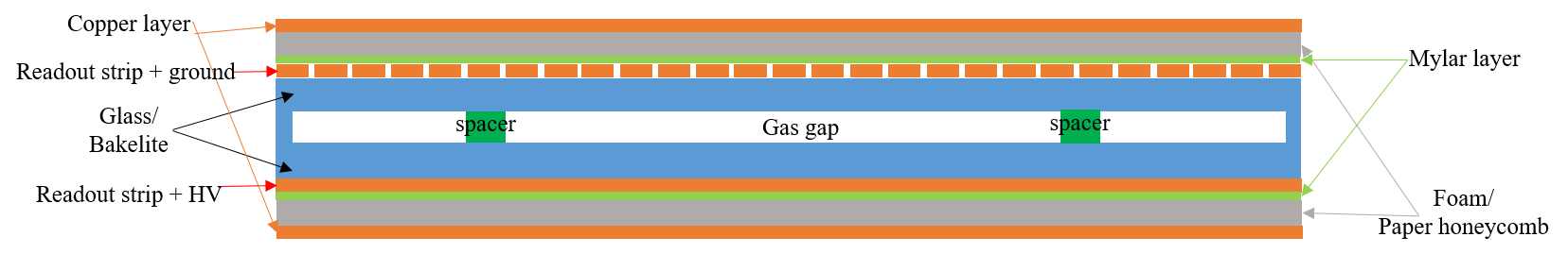
RPC is a kind of gaseous detector wihich was invented during 1980s [1] [2]. Until now, it has been one of the most widely used detectors in High Energy Physics (HEP) experiments. The traditional structure of RPC is shown is Fig. 1, including 1 gas gap and 2 readout panels. The gas gap consists of spacers and resistive plates with graphite and mylar layers coated on the surface. Commonly the material of resistive plates is glass ( ~ cm) or bakelite ( ~ cm). Two readout panels with orthogonal strips are assembled on both sides of the gas gap.
As indispensable components of RPC detectors, the graphite layers play an important role. The working voltage is applied on these layers and the charge of avalanche also dissipates through them. The surface resistivity of the these layers is an important parameter which need to be tuned precisely. If the surface resistivity is lower than several hundreds , the induced signals will spread to a large area through the graphite layers and result in a large cluster size [3]. On the other hand, if the surface resistivity is too high, the large electric potential difference will be formed along the surface of detector. This will reduce the effective working voltage in the region far away from the injection point of working voltage especially for RPCs with very large size and in the high irradiation conditions. In this case, the surface resistivity must be controlled in a range from several hundreds to several .
The strict requirement of the surface resistivity bings some difficulties in coating the graphite layers on the resistive plates. And during the coating, it is also difficult to keep the uniformity on the whole surface. This is one of the dominated uncertainties in terms of manufacturing technology. In order to improve these disadvantages, the new layout which removes the graphite layers is proposed and tested in the paper. What’s more, this new layout can also simplify the structure of RPC detector.

2 Design of new RPC structure
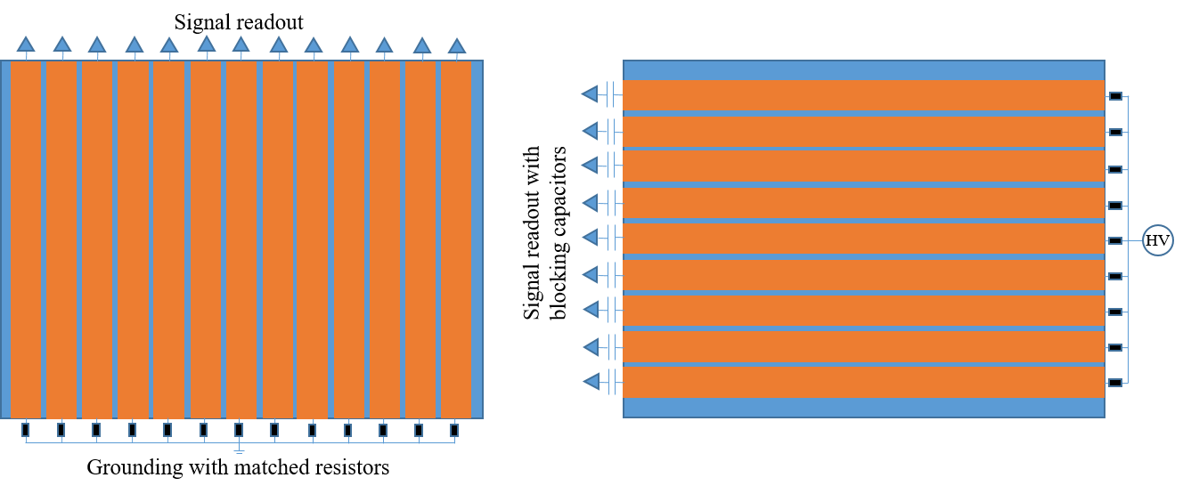
In the traditional structure of RPC, there are two layers of graphite coated on both sides of the gas gap and connected with ground and high voltage (HV) respectively. The new design shown in Fig. 2 will remove these two graphite layers. In this improved structure, the strips are attached directly to the glass or bakelite plates and used for both signal pick-up and voltage applying. To achieve these goals, as shown in Fig. 3, one end of the strip is connected with ground or HV via the matching resistors while the other end is connected with front-end electronics for signals pick-up.
With this new design, in principle, the quality of induced signals is not affected or even slightly improved since the strips are closer to the avalanche. The potential along the surface of each side of the gap is uniform no matter how large the detector size is since the strips are made of copper and the matching resistors are negligible (~20 to 30 ) compared with the glass or bakelite plates. Fot the signal readout, the detailed structures for the ground and HV strips are different. In the HV strips, the blocking capacitors are used to isolate the front-end electronics and the power supply to eliminate the latent risk of very high potential (~6000 V for RPC with 1 mm gas gap). At the same time, the ground strips are much safer, consequently the blocking capacitors could be ignored in the case of high quality of electrical grounding. At last, the problem of large cluster size caused by the low surface resistivity of the graphite layer can also be eliminated since the signals will not spread through this layer.
3 RPC prototype test
To verify the new structure, two RPC prototypes made of glass plates are produced and tested in a cosmic ray telescope. The thickness of gas gaps is 1 mm and the pitch of readout unit is 27 mm (25 mm strip + 2 mm gap). The induced signals are read out from the ground strips via the homemade amplifiers with gain ~15. Since the application of blocking capacitor is a mature technology which has been applied successfully in many detectors, such as the ATLAS Monitored Drift Tubes (MDT) [4], signals from the HV strips are not tested emphatically in this paper.
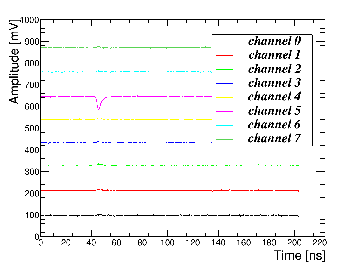
The classic measurement system built by two RPCs and triggered by the coincidence of two scintillators is set up to measure the performance of the 2 RPC prototypes [5]. The waveform of signals are recorded completely by the CAEN digitizer V1742 with sampling frequency of 5 GS/s. When the working voltage is higher than 5600 V, signals with very good quality can be collected by the system. An example of signal waveform is shown in Fig. 4. The negative pulse in channel 5 is the induced signal.
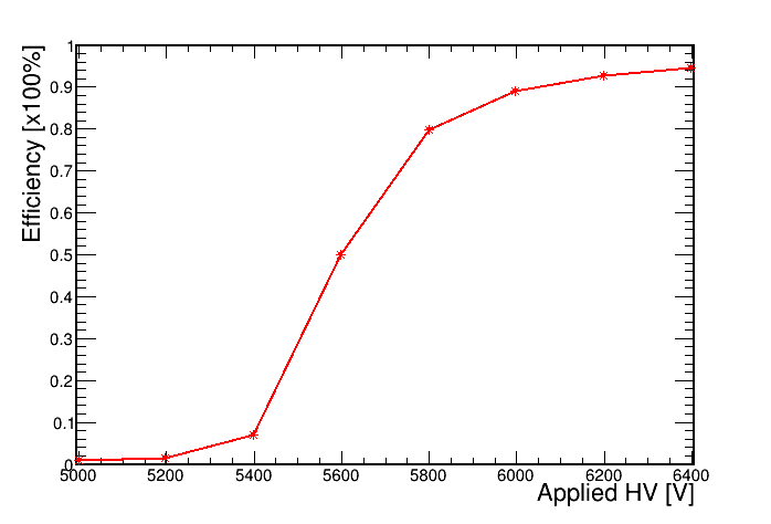
The efficiency measurement is performed by keeping the HV of one RPC at 6400 V as reference and varying that of the other one from 5000 V to 6400 V. A sample of good cosmic muons can be selected by requiring the coincidence of the reference RPC and 2 scintillators. The efficiency is calculated as the ratio of signal number in the tested RPC to that in this sample. The efficiency plateau is drawn in Fig. 5. The maximum at 6400 V is 94.3% while the minimum at 5000 V is 0.9%.
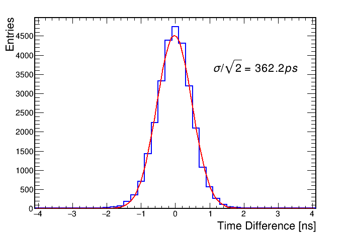
The time resolution is measured when both of the 2 RPCs are working at 6400 V. The difference of time-of-arrival between the 2 RPCs is shown in Fig. 6. Fit this distribution with a Gaussian function and the sigma divided by sqrt(2) is the measured time resolution since the two RPCs are the same. The time resolution is measured to be 362.2 ps.
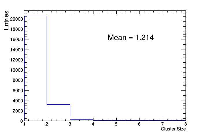
As the removal of graphite layer, the cluster size is expected to be smaller. The average value of this variable is measured to be 1.21 and the distribution is shown in Fig. 7.
Compared with the RPCs with traditional structure [6], our RPC prototypes have the similar performance and simplified structure.
4 Summary
To improve the disadvantage of graphite layers in RPC detector, the RPC prototypes which remove these layers and use the strips as both signal pick-up and voltage applying is proposed and tested. High efficiency and good time resolution have been measured. In the future, this improvement of graphite layers could also be attempted in some other gaseous detectors such as MRPC and TGC. This will be a progress in eliminating the negative effect from the ununiformity of graphite layers and simplifyng the structure of some gaseous detectors.
Acknowledgement
This study was supported by National Key Programme for S&T Research and Development
(Grant NO.: 2016YFA0400100) and the National Natural Science Foundation of China
(No. 11961141014). This work is also supported by the State Key Laboratory of
Particle Detection and Electronics, SKLPDE-ZZ-202011 and in part by the CAS
Center for Excellence in Particle Physics (CCEPP).
References
- [1] R. Santonico, R. Cardarelli, Nucl. Instr. and Meth. 187(1981) 377
- [2] R. Santonico, R. Cardarelli, Nucl. Instr. and Meth. 263(1988) 20
- [3] X.Y. Xie et al, A new approach in simulating RPC and searching for the causes of large cluster size of RPC, 2019 JINST 14 C09012
- [4] Alessandro Di Girolamo, Studies on the performance of the Monitored Drift Tubes of the Atlas detector, http://diggi.web.cern.ch/diggi_phd_thesis.pdf
- [5] Q. Li et al, Performance study of HL-LHC ATLAS RPC prototype, 2019 JINST 14 C09022
- [6] ATLAS Collaboration, Technical Design Report for the Phase-II Upgrade of the ATLAS Muon Spectrometer, https://cds.cern.ch/record/2285580