A 500 MS/s waveform digitizer for PandaX dark matter experiments
Abstract
Waveform digitizers are key readout instruments in particle physics experiments. In this paper, we present a waveform digitizer for the PandaX dark matter experiments. It supports both external-trigger readout and triggerless readout, accommodating the needs of low rate full-waveform readout and channel-independent low threshold acquisition, respectively. This digitizer is a 8-channel VME board with a sampling rate of 500 MS/s and 14-bit resolution for each channel. A digitizer system consisting of 72 channels has been tested in situ of the PandaX-4T experiment. We report the system performance with real data.
1 Introduction
The dark matter (DM) makes up around 27% of the Universe, but its nature remains to be elusive. Direct detection and identification of DM are among the most pressing challenges for contemporary experimental physics. The PandaX project consists of a series of experiments that use xenon as the detection media. These experiments have produced most stringent limits on the couplings of some well-motivated classes of DM to ordinary particles [1, 2, 3, 4, 5, 6, 7, 8, 9, 10, 11].
In PandaX DM experiments, the central apparatus is a dual-phase xenon time projection chamber (TPC). Its cathode and gate are applied with separate High Voltage (HV) to provide the drift electric field and extraction field. Particle interacting with one of the xenon atoms in the sensitive volume can generate a prompt flash of scintillation lights (S1) and ionized electrons. The latter are drifted up and extracted into the gaseous region where they produce electroluminescence, namely a second flash of scintillation lights (S2). These lights are detected by two arrays of photomultipliers (PMTs) instrumented at the top and the bottom of the TPC. The electrical signals from PMTs are constantly sampled and digitized by waveform digitizers.
The digitized samples constitute the most fundamental data for offline analysis. For rare event search experiments like PandaX, all useful waveforms should be read out, since they carry all information including the charge, time, pulse shape and so on. However, not every sample can be read out. In the previous experiments PandaX-I and PandaX-II, the waveform of each PMT is sampled every 10 ns at a 14-bit resolution. So the data rate per digitizer channel is 190 MB/s, which is already above the 85 MB/s maximum readout bandwidth per digitizer. Given the total number of channels (for example, 158 in PandaX-II), the total bandwidth becomes extremely large. Therefore, digitized samples must be read out selectively.
In PandaX DM experiments, two data acquisition (DAQ) schemes have been developed, depending on chosen digitizers. In PandaX-I and PandaX-II [12, 13], the readout of the digitizers (CAEN V1724, 100 MS/s sampling rate) relies on global external trigger signals from a trigger system, which is designed for capturing relatively large S2 signals. For each trigger, data from all channels in a fixed time window around the trigger time can be read out, with or without baseline suppressed depending on the need. In order to save both S1 and S2 signals, the time window needs to larger than twice of the maximum electron drift time. In the current experiment PandaX-4T, another digitizer (CAEN V1725, 250MS/s) is used [14]. The readout does not require external triggers. This is usually called triggerless readout. Each channel can be self-triggered and read out independently with baseline suppressed.
The data acquired by external-trigger-based DAQ are affected by inefficiencies of identifying S2 signals by the trigger system. In many DM searches, a lower cut on S2 signal is applied. For example, in the PandaX-II light DM-electron analysis [9], the lower cut is set to be the same as the trigger threshold, which refers to the size of S2 signals when the trigger efficiency is 50% [13]. In this case, the S2 trigger inefficiency is one of the dominant causes for DM detection efficiency loss. On the other hand, the triggerless DAQ is designed to record all self-triggered data from all channels. S1 and S2 signals are only identified offline. S2 trigger inefficiency becomes irrelevant.
However, triggerless readout does not meet all experimental needs. In this readout scheme, a readout buffer is usually needed to save digitized samples, together with other information such as the trigger time stamp, before they are finally read out to the DAQ server. Due to limited buffer space and readout bandwidth, the digitizers can become busy due to fullness of the buffer. In the commissioning runs of PandaX-4T [14], the busy effect was found to be negligible for the event reconstruction when the total date rates were less than about 80 MB/s for dark matter runs and most calibration runs. In some conditions with higher data rates, noticeable systematic errors were observed in the event reconstruction [14]. Therefore, it might be more appropriate to use external-trigger-based scheme with baseline suppression in these run conditions. In addition, to study the baseline suppression effect in reconstructing S1 and S2 signals, it is also desirable to read out full waveforms including both S1 and S2 signals during one trigger time window without baseline suppressed. However, the chosen digitizers in PandaX-4T (V1725) cannot record both S1 and S2 signals for each trigger with baseline suppressed.
Besides the flexibility in readout schemes, a digitizer with higher sampling rate is desired. Higher sampling rate is potentially useful for improving the pulse shape discrimination in dual-phase xenon TPC experiments [15, 16]. In addition, a new type of PMTs are being considered for future PandaX experiment. These PMTs exhibit shorter pulses for single photoelectron (SPE) signals compared to the 3-inch PMTs used in PandaX-4T. This also calls for a digitizer with a higher sampling rate.
In this paper we present a 500 MS/s waveform digitizer designed to support both external-trigger and triggerless readout schemes. A digitizer system consisting of 72 channels was built to acquire data in the PandaX-4T experiment in June 2021, after its commissioning runs. The in situ system performance is presented. This digitizer has also been used to evaluate the new PMTs. Its performance of measuring SPE signals is presented.
2 The Digitizer Design

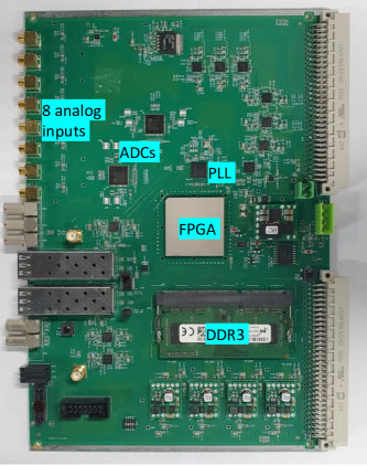
The digitizer is a 6U VME-standard module, as shown in Figure 1. It combines two analog-to-digital converters (ADCs) with a Field Programmable Gate Array (FPGA). Each input single-ended analog signal is converted to a differential pair through a differential amplifier. The gain is set to be 1.6. After the amplifier, the signal is attenuated by resistors and a low-pass filter before entering into the ADCs. The overall amplification is about 1.25. In the ADC, four input signals are simultaneously sampled and digitized with a sampling rate of 500 MS/s and a 14-bit resolution. The dynamic range is set to be 2.16 Vpp. The digital data are transferred to the FPGA through the high-speed JESD204B serialized interface [17].
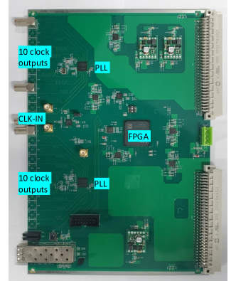
The ADC sampling clock and the JESD204B receiver core clock in the FPGA are provided by a JESD204B compliant and programmable clock jitter cleaner with internal phased-locked loops (PLLs). The system reference (SYSREF) signal, required by the JESD204B subclass 1 standard, acts as a common timing reference to synchronize internal framing clocks in the ADCs and the FPGA. For synchronization among different digitizers, a common-source external clock is required to be the reference clock input of the PLL. This is achieved with a self-designed clock fanout VME module (see Figure 2). For each data acquisition run, common external start-run signals (synchronized with the PLL clock) are sent into all digitizers, so the internal trigger time counters begin to increase at the same rising edge of the start-run signals. In a multi-digitizer system with the clock fanout module, the channel-to-channel synchronization within single board and between two boards is measured to be better than 0.2 ns, which is sufficiently precise for PandaX DM experiments given that a typical S1 signal is O(100) ns wide. In addition, several other clocks are required. A clock is needed to program the ADCs and clock jitter cleaner. Reference clocks are needed for the serial transceivers in the FPGA (denoted as MGT_CLK in Figure 1 left). These clocks are provided by a clock buffer with an oscillator as the input.
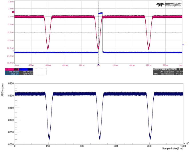
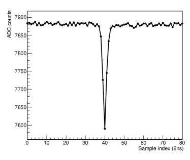
Data processing algorithms are implemented in the FPGA. For external-trigger-based DAQ, a large time window around the trigger time is required. In PandaX-4T commissioning runs, the maximum drift time is 0.84 ms. The buffer space per channel is required to store at least 1 ms of data. This alone already exceeds the internal memory capability of the FPGA. Thus, a DDR3 SDRAM memory is used to cache the data from ADCs. Once an external trigger is received, the data in DDR3 are read out. This is demonstrated in Figure 3, where the 2 ms-long data per channel are read out with the trigger at the middle of the time window. This shows that the new digitizer can record both S1 and S2 signals in one external trigger at the PandaX DM experiments.
For self-trigger based DAQ, the real-time baseline is calculated dynamically with a moving average algorithm. When a digitized sample exceeds the baseline by a configurable threshold, an event header, consisting of the board and channel number, trigger time stamp and busy time counter, is written into a readout FIFO in the FPGA. Afterwards, the whole pulse exceeding the threshold and a limited number of samples before and after the pulse are saved into the same FIFO. The depth of this FIFO is configured to be 65536 samples (13 us) for each channel. This is large enough for our data taking described in next section, given the self-trigger rate per channel is 200-300 Hz and the average number of ADC samples per trigger is around 150. However, it is possible that the data in the readout FIFO are not read out fast enough. When it is close to be full, the busy time counter will be increased until the FIFO becomes available again. With this counter we can monitor the dead time for each channel. In addition, the self-trigger algorithm is designed to accept external triggers. This can be used for LED light calibrations.
The digitizer connects to the DAQ server by a small form-factor pluggable plus transceiver (SFP+) with a fiber optic link. A Gigabit Ethernet protocol SiTCP [18] is used in the FPGA to transfer data from the digitizer to the DAQ server through the SFP+. Another SFP+ slot is reserved for future development. For example, it can be used to send out the real-time waveforms of the digitizer. The summed waveforms from all digitizers can be used to generate external trigger signals for the digitizers when operated in the external-trigger mode. In addition, the digitizer includes several LVDS lanes (Figure 1 lower left region), which are reserved for future development as well. They can provide real-time time-over-threshold (ToT) signals, like the CAEN V1724 and V1725 digitizers. Such ToT signals were used for the trigger system in previous experiments PandaX-I [12] and PandaX-II [13]. Unlike the TOT signals, the summed waveforms carry the absolute pulse height information. We might be able to improve the trigger performance with the new digitizers using the summed waveforms.
3 Performance
3.1 Performance in PandaX-4T
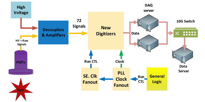

To demonstrate the performance of the new digitizers, we built a 72-channel digitizer and DAQ system (see Figure 4) in situ of PandaX-4T experiment in June 2021, after its commissioning runs. 72 bottom 3-inch PMTs (Hamamatsu R11410-23) are used for the data taking. The DAQ system is similar as the current one in PandaX-4T [14]. The data of each digitizer are transmitted to a DAQ server through individual fiber optic links with commercial PCI-E Ethernet cards. Two DAQ servers are used. All data are transferred to another data server and saved into the disk for offline analysis.
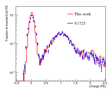
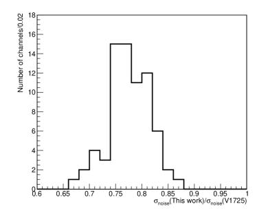
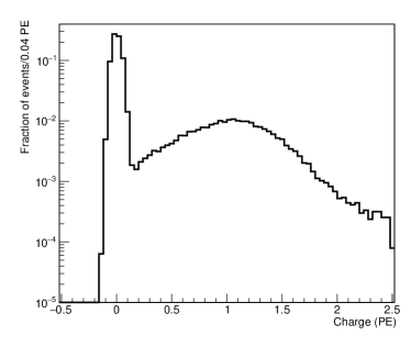
The system performance is evaluated in two folds. First is the measurement of SPE signals, which are the smallest signals in the experiment. For the new system, the gain of each PMT channel (including the digitizer) is recalibrated with SPE signals using a low-intensity LED. The charge distribution with pedestal contribution of a typical 3-inch PMT is shown in Figure 5 left. Compared to the V1725 digitizers, the SPE distribution is almost unchanged when using the new digitizers, because it is dominated by the PMT gain fluctuations. However, due to the higher sampling rate and the amplifiers in the new digitizers, the pedestal width is reduced from 0.093 PE to 0.072 PE on average. This is equivalent to a 30% improvement on the signal-over-noise ratio.
Second is the reconstruction of physical events. A 14.8-hour dataset were recorded using the new digitizers, operated in the triggerless mode. The self-trigger threshold is set to be 22 ADC counts. For a typical 3-inch PMT channel, this corresponds to 0.28 PE. In this run, no dead time is observed for most channels. For others, the dead time is negligible. The maximum dead time among all channels is 0.003 ms during the 14.8 hours of data taking. In the same run, data from other PMT channels were recorded using V1725 digitizers. The typical threshold is about 1/3 PE [14]. Before this run, the liquid xenon was irradiated for 1/2 day with a Pu-C neutron source. So we expect to record a large number of high-energy events with energies around 164 keV (131mXe) and 236 keV (129mXe). The event rates of the two rays measured from two independent digitizer systems are expected to be consistent.
The rates are measured from the reconstructed energy distribution. The procedures are as follows. The recorded raw data are processed in a similar way as the first PandaX-4T DM analysis [11]. Hits with amplitudes above the trigger threshold are identified from individual channels. Signal is then defined as a cluster of hits with tail-to-head gap not greater than 60 ns, in order to capture nearly all scintillation lights from xenon excimers with lifetime 4 ns and 21 ns from the single and triplet states, respectively. The inefficiency of such clustering gap requirement has been studied in Ref. [11] and found to be negligible using data driven approaches. The S1-like and S2-like signals are tagged based on the width of the cluster waveform enclosing 10% to 90% cumulative charge. In addition, S1 and S2 signals are required to have a charge qS15 PE and qS2200 PE, respectively.
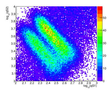
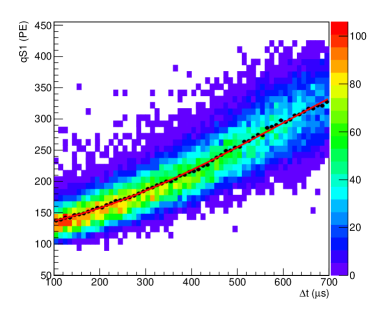
An event is then defined by combining all S1-like and S2-like signals within a time window of 1 ms. The S1 and S2 signals with largest charges are selected to form a pair. The electron drift time ( between S2 and S1 signals) is required to be above 100 s and less than 700 s. This serves as a fiducial volume selection which removes 68% background events, while keeping 70% signals events from the two high-energy s. No other selection cuts are applied. The correlation between S2 and S1 charge is shown in the Figure 6 top left panel. There are two distinct bands. The lower and the upper one correspond to the 164 keV and the 236 keV s, respectively.
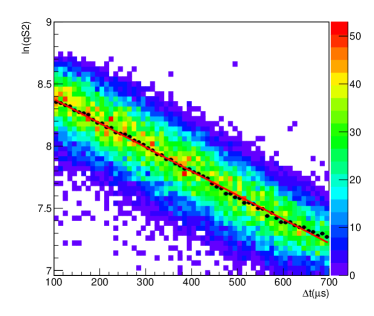
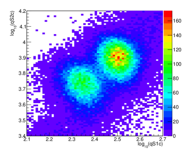
The qS2 and qS1 are corrected before they are used to reconstruct the energy. Due to electronegative impurities in the liquid, qS2 is exponentially reduced as the drift time increases, as shown in the Figure 6 top right panel. Here, the 164 keV data are selected around the lower band in the Figure 6 top left panel. The corrected S2 charge is given by qS2cqS2, where is the electron life time obtained from the fit in Figure 6 top right panel. When the interaction happens closer to the liquid surface, the scintillation lights of S1 signals are more difficult to be detected by the PMTs due to light reflections on the TPC wall. This is shown in the Figure 6 bottom left panel using the same 164 keV data. The corrected S1 charge becomes qS1cqS1, where is the polynomial function in Figure 6 bottom left panel, and represents the average value of the fucntion from 100 and 700 s. The corrected charge qS2c vs qS1c is shown in the Figure 6 bottom right panel. As expected, the two bands become more localized after corrections.

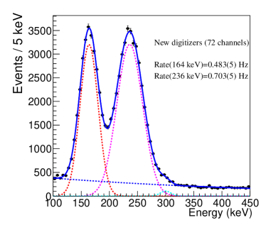
Finally, the combined energy is reconstructed as EeV , where is the photon detection efficiency, is the product of the electron extraction efficiency and the single electron gain. The is taken from Ref. [11] but adjusted taking into account that only bottom PMTs are used here for the S1 charge measurement while both top and bottom PMTs are used in Ref. [11]. The values of and are solved such that the 164 keV distribution is peaked at the right position. Figure 7 left shows a typical waveform of the S1 and S2 signals with charges and combined energy compatible with a 164 keV deposition in the liquid. Figure 7 right shows the energy distribution. An extended likelihood fit is used to extract the number of signal events. The event rates for the 164 keV and 236 keV rays are measured to be Hz and Hz, respectively.
The data recorded with V1725 digitizers in the same run are processed with the same procedures described above. The is also taken from Ref. [11] and adjusted according to the fact that 72 bottom PMTs are not used for S1 and S2 measurements. The measured event rates of the two rays are Hz and Hz, respectively. These results are consistent with the previous measurements within two standard deviations. This provides a cross validation for our new digitizers and the V1725 digitizers.
3.2 Performance with the new PMTs for PandaX-30T
For the future experiment PandaX-30T, a new type of 2-inch PMTs (Hamamatsu R12699-406-M4) are being considered. Compared to the 3-inch PMTs used in PandaX-4T experiment, the new PMTs have smaller radioactivity level. In addition, each PMT consists of 4 -inch PMT array. So these PMTs can provide better photon coverage and better position measurement in dual-phase xenon TPC experiments.
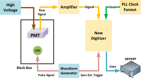
Our new digitizers have been used to evaluate the new PMTs, with the setup shown in Figure 8. Figure 9 left shows a typical waveform of the SPE signals recorded by the new digitizer. The typical SPE signal pulse lasts around 10-15 ns, which is about a factor two shorter than the 3-inch PMTs used in PandaX-4T. Given that a 250 MS/s digitizer is used in PandaX-4T, a 500 MS/s sampling rate is a reasonable choice for the new PMTs. Figure 9 right shows the measured charge distribution from one output channel of the new PMT. The SPE peak is clearly distinguishable from the pedestal.
4 Summary
In summary, we presented a 8-channel 500 MS/s waveform digitizer that is designed to support both triggerless readout and external-trigger-based readout. Using real data from PandaX-4T, the triggerless readout of the new digitizers have been cross validated with the current digitizers used in the experiment. The new digitizers have been used to evaluate the new 2-inch PMTs for future experiment. The capability of recording long waveforms before and after the external trigger is demonstrated with a waveform generator. This shows the new digitizer should be able to record both S1 and S2 signals in one trigger time window. A trigger system is under development. The system is expected to analyze the real-time waveforms from the new digitizers and provide external triggers for the digitizers when operated in the external-trigger mode. A joint test of the trigger system and the digitizer system will be performed in the future.
5 Acknowledgement
This project is supported by grants from the Ministry of Science and Technology of China (No. 2016YFA0400301 and 2016YFA0400302), a Double Top-class grant from Shanghai Jiao Tong University, grants from National Science Foundation of China (Nos. 11875190, 11505112, 11775142, 11755001 and 12090063), supports from the Office of Science and Technology, Shanghai Municipal Government (18JC1410200), and support also from the Key Laboratory for Particle Physics, Astrophysics and Cosmology, Ministry of Education. This work is supported also by the Chinese Academy of Sciences Center for Excellence in Particle Physics (CCEPP). We thank the PandaX-4T collaboration for their support for our in situ test of the new digitizers. We acknowledge useful discussions and help on the hardware development and test from Qi An, Shubin Liu, Changqing Feng, Zhongtao Shen, Shuwen Wang at the State Key Laboratory of Particle Detection and Electronics, University of Science and Technology of China.
References
- [1] X. Xiao et al. PandaX Collaboration, Low-mass dark matter search results from full exposure of the PandaX-I experiment, Physical Review D, 92, 052004 (2015)
- [2] A. Tan et al. PandaX-II Collaboration, Dark Matter Results from First 98.7 Days of Data from the PandaX-II Experiment, Physical Review Letters,117, 121303 (2016)
- [3] C. Fu et al. PandaX-II Collaboration, Spin-Dependent Weakly-Interacting-Massive-Particle–Nucleon Cross Section Limits from First Data of PandaX-II Experiment, Physical Review Letters, 118, 071301 (2017)
- [4] X. Cui et al. PandaX-II Collaboration, Dark Matter Results From 54-Ton-Day Exposure of PandaX-II Experiment, Physical Review Letters, 119, 181302 (2017)
- [5] C. Fu et al. PandaX-II Collaboration, Limits on Axion Couplings from the First 80 Days of Data of the PandaX-II Experiment, Physical Review Letters, 119, 181806 (2017)
- [6] X. Chen et al. PandaX-II Collaboration, Explore the Inelastic Frontier with 79.6-day of PandaX-II Data Physical Review D, 96, 102007 (2017)
- [7] J. Xia et al. PandaX-II Collaboration, PandaX-II Constraints on Spin-Dependent WIMP-Nucleon Effective Interactions, Physics Letters B, 792, 193-198 (2018)
- [8] X. Ren et al. PandaX-II Collaboration, Constraining Dark Matter Models with a Light Mediator at the PandaX-II Experiment, Physical Review Letters, 121, 021304 (2018)
- [9] C. Cheng et al. PandaX-II Collaboration, Search for Light Dark Matter-Electron Scatterings in the PandaX-II Experiment, Phys. Rev. Lett. 126, 211803 (2021)
- [10] J. Yang et al. PandaX-II Collaboration, Constraining self-interacting dark matter with the full dataset of PandaX-II, SCIENCE CHINA Physics, Mechanics & Astronomy, 64, 111062 (2021)
- [11] Y. Meng et al. PandaX-4T Collaboration, Dark Matter Search Results from the PandaX-4T Commissioning Run, arXiv:2107.13438
- [12] X. Ren et al. The Electronics and Data Acquisition System for the PandaX-I Dark Matter Experiment, JINST 11, T04002 (2016)
- [13] Q. Wu et al. Update of the trigger system of the PandaX-II experiment, JINST 12, T08004 (2017)
- [14] J. Yang et al. Readout electronics and data acqusition system of PandaX-4T experiment, arXiv:2108.03433
- [15] J. Kwong et al. Scintillation pulse shape discrimination in a two-phase xenon time projection chamber, Nucl. Instrum. Meth. A 612, 328-333 (2010)
- [16] , S. Wang Study on Readout Electronics System for PandaX-nT Dark Matter Direct Experiment, , PhD thesis, University of Science and Technology of China (2020)
- [17] JEDEC, JESD204B.01, Serial Interface for Data Converters, 2012
- [18] J. Uchida, Hardware-based TCP processor for gigabit ethernet. IEEE Transactions on Nuclear Science, 55(3), 1631-1637 (2008)
- [19] AD8009 1 GHz, 5500 V/s Low Distortion Amplifier, https://www.analog.com/en/products/ad8009.html