Dislocation-CNT Interactions in Aluminium at the Atomic Level
Abstract
The interaction between edge dislocations and carbon nanotubes (CNTs) embedded into an Al matrix is investigated. Both pristine and Ni-coated CNTs are considered. It is demonstrated that the embedded CNTs lead to a flow stress contribution equivalent to that of an array of non-shearable inclusions that are by-passed via the Orowan mechanism. The strain hardening mechanism associated with multiple dislocation passes shows, however, characteristic differences from the Orowan picture that indicate that the embedded CNTs behave analogous to embedded voids.
1 Introduction
Carbon nano-particles (CNP), in particular carbon nanotubes (CNT) and Graphene (GP) sheets with their excellent mechanical properties [1, 2, 3, 4] are considered as promising candidates for fillers in composites where the matrix is a lightweight metal like Al and Mg. Such composites might have applications in the aeronautical, electrical and automotive industries. The benefits, in view of mechanical properties, of embedding well-dispersed carbon nanoparticles into metals are potentially huge, for discussion see e.g. [5, 6, 7, 8]. They derive on the one hand from classical composite mechanics – strong reinforcing fibers and platelets will carry part of the load and increase effective elastic moduli – on the other hand from the interaction of nanoparticles with matrix defects and from their interference with deformation and failure mechanisms in pristine metals: Strong embedded nanoparticles can potentially bridge incipient cracks and impose strong constraints on dislocation motion, thus potentially increasing yield strength, fracture strength, and possibly also toughness. Added benefits can be drawn from the nanoscale dimensions of the reinforcing particles in terms of small spacing (high Orowan stresses), high specific surface area and very high aspect ratio of the tubular or flake- like particles, resulting in efficient crack bridging and high creep resistance as dislocations cannot easily climb around the embedded particles [9, 10, 11, 12, 13, 14, 15, 16, 17, 18].
Atomistic simulation can play an important role for understanding strengthening mechanisms in CNP reinforced metals, and in particular the interactions of CNPs with dislocations. This can be envisaged in analogy with interactions of dislocations with other types of embedded particles such as precipitates, for which a vast body of atomistic simulation studies exists, exploring aspects such as the role of matrix/precipitate interface, precipitate stiffness, size, shape, orientation of precipitate and dislocation type [19, 20, 21, 22, 23, 24]. An extensive review of atomistic simulation of dislocation-obstacle interactions considering different parameters in various metals can be found e.g. in [25].
Regarding the interaction of dislocations in metals with embedded CNPs, there exist few simulation studies. Kim et al. [26] complement their experimental investigation of layered metal-graphene nanolayer composites with molecular dynamics (MD) simulations of the interaction of a dislocation with an embedded graphene layer and find that dislocations get arrested by elastic interactions with the embedded graphene before they reach the graphene-metal interface. A similar dislocation arrest mechanism was deduced by Chang et al. [27] from MD simulations of indentation tests on Ni-GP nanolayers. Liu et al. [28] use MD to study the shearing of Cu-G multilayers with (111) and (100) stacking and dislocation-free Cu matrix, and shear conducted along [100] (100) and [112] (111) directions in such a manner that the graphene layers intersect the plane of shear. In these cases a significant strengthening was found as compared to pristine Cu; this was attributed to the dual confining effect of the Cu matrix on the GP filler (prevention of wrinkling) and of the GP sheets on the Cu matrix (blocking of dislocations).
In this study we focus on reinforcement by carbon nanotubes and present atomistic simulations of edge dislocations in Al interacting with pristine and nickel coated CNTs (henceforth referred to as NiCNTs) of different size and inter-particle spacing. The rationale of considering NiCNTs for Al matrix reinforcement has been explored elsewhere: Ni coating of CNTs very significantly improves interfacial adhesion between Al matrix and reinforcing CNTs, thus improving load transfer and preventing nanotube pull-out [8]. Here we investigate how the modified interface affects the interaction between embedded CNTs and matrix dislocations.
2 Methods and Results
The atomistic simulations presented in this work were performed with the molecular dynamics code LAMMPS [29] (version 16 Mar 2018). Atomsk package [30], and VNL builder in QuantumATK [31, 32] were used to create the initial atomic configurations. Data visualization and post-processing were obtained with the help of the Open Visualization Tool (OVITO) [33]. Common neighbour analysis (CNA) [34, 35] was used to analyze the crystallographic structure around atoms and to identify defects and dislocations in the Al matrix.
2.1 Interatomic potentials
To describe atomic interactions, we use the standard AIREBO potential [36, 37] for carbon-carbon, and the EAM/alloy potentials of Mishin [38] for metal-metal interactions. Interfacial interactions between CNTs and metals are described by using Morse potentials for Al-C and Ni-C interfaces which have been parametrized using DFT calculations and fitted to represent physisorbed Al/GP and Ni/GP interfaces [8]. The energy function in the Morse potential has the form , where is the bond distance, an equilibrium bond distance, is the well depth, and controls the stiffness of the potential. The obtained parameters for the Al-C Morse potential are = 0.004 eV, = 4.52 and = 1.0 and for the Ni-C Morse potential = 0.0048 eV, = 4.18 and = 1.15 .
2.2 Sample Preparation
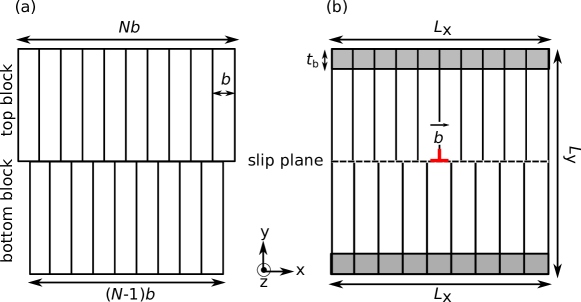
We use the Atomsk package [30] to construct an aluminum block in the form of a parallelepiped containing an edge dislocation, following the procedure described in Ref. [25]. The edges of the Al block are aligned with the axes of a Cartesian coordinate system where the axis points in the [-1-12] direction, the axis in the [-1-1-1] direction, and the axis in the [-110] direction of the fcc crystal lattice. An edge dislocation of Burgers vector is created by cutting the block along the (-1-1-1) plane (the plane of the coordinate system) and adding one (-110) lattice plane in excess to the top half (Fig. 1 (a)). The upper half is then subjected to affine compression in direction with a total length reduction of , and the lower half to affine elongation by , such that both have the same length in direction. The blocks are then merged along the (-1-1-1) plane. Periodic boundary conditions are imposed in direction (line direction of the dislocation) and in direction (glide direction). After constructing the initial simulation box, the system is relaxed using the fast inertial relaxation engine (FIRE) algorithm [39]. The system is accepted as relaxed when both the change of energy between successive iterations divided by the energy magnitude is less than or equal to the tolerance () and the 2-norm (length) of the global force vector is less than the threshold value of eV/ as in [23]. The shaded regions in Fig. 1 show the boundary layers. Atoms in the boundary layers of thickness = 14 are considered completely rigid during the relaxation by setting all forces on these atoms to zero. After the relaxation, an edge dislocation of Burgers vector is present in the Al matrix.
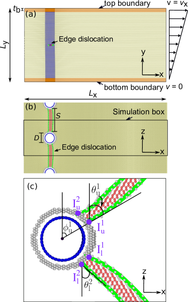
The next step is to embed a single walled carbon nanotube (SWCNT) into the Al block in such a manner that it is threading the Al block from top to bottom along the axis. We consider pristine as well as Ni coated CNTs. The procedure for Ni coating has been discussed in detail elsewhere [8]. To equilibrate Ni atoms on the CNT surface and allow for the possible formation of a continuous Ni coating [40, 41], a layer of Ni atoms of thickness 7.0 around a CNT(10,10) with a diameter of 14 is annealed at 2300K (i.e., above the melting temperature of Ni) for 20 ps in the ensemble at zero pressure, and then quenched to 0.1 K at a rate of 10 K/ps. During this anneal-quench cycle, the CNT atoms are kept fixed. To embed a pristine or Ni-coated CNT into the Al block, the CNT is placed inside the block and any Al atoms are removed that are located either inside the CNT or within a distance of less than 3.0 from C and/or Ni atoms. The system is subsequently relaxed using the FIRE algorithm. A detailed illustration of the resulting Al-CNT composite block with one edge dislocation (split into two Shockley partial dislocations after the minimization) is shown in Fig. 2. In this figure, is the distance between the CNT and its image due to the periodic boundary conditions in direction. It can be calculated as where is the simulation box length in direction and is the CNT diameter.
In the present work, we investigate the influence of three parameters on the critical shear stress required for the dislocation to pass the array of periodically replicated embedded CNTs. Thus we vary the size of the simulation box in direction, which in view of the periodic boundary conditions determines the CNT spacing , as well as the CNT diameter and the matrix-CNT interface, which is modified by considering both CNTs and coated NiCNTs. For NiCNTs, is defined as the outer diameter of the Ni coating. Table 1 details the geometrical parameters used in the simulations.
| Samples | |||||
|---|---|---|---|---|---|
| Pristine CNT | |||||
| 1 | 402 | 208 | 99 | 28 | 71 |
| 2 | 402 | 208 | 198 | 28 | 170 |
| 3 | 402 | 208 | 297 | 28 | 269 |
| 4 | 402 | 208 | 396 | 28 | 368 |
| 5 | 402 | 208 | 382 | 14 | 368 |
| 6 | 402 | 208 | 438 | 42 | 368 |
| Ni-coated CNT | |||||
| 1 | 402 | 208 | 396 | 28 | 368 |
The initial configuration of a typical simulation is shown in Fig. 2. During the relaxation step which follows insertion of the CNT, the dislocation aligns with the CNT and its periodic images, reducing its line energy by intersecting the surface of the hollow cylinder surrounding the CNT. This represents the minimum energy configuration of the unloaded dislocation-CNT system. For later use we introduce the following notations: The origin of the coordinate system is located at the point where the slip plane intersects the centroidal axis of the CNT. The arm of the dislocation extending from the CNT in direction to the periodic boundary is denoted as ’upper’ arm (UA), the arm extending in direction as ’lower’ arm (LA). The local dislocation orientation is characterized by the angle between the dislocation line direction and the direction. Angles are distinguished by subscripts (u,l) where refers to the upper and to the lower arm, and by superscripts (1,2) where 1 denotes the leading and 2 the trailing partial dislocation. The points of intersection of the leading (trailing) partial dislocation of the upper (lower) arm with the cylinder surrounding the CNT are accordingly denoted as . In cylindrical coordinates with the CNT axis as cylinder axis these intersection points are located at the points where , i.e., the angle defines the direction of the vector connecting the CNT center and the intersection point of the leading (trailing) partial of the upper (lower) dislocation.
2.3 Atomistic simulation
Shear deformation of the simulated sample is imposed by rigidly displacing the top boundary layer in direction with a velocity which is constant in time, while a velocity of zero is imposed on the atoms in the lower boundary layer. Atoms located between the top and bottom boundary layers are assigned initial velocities in direction according to
| (1) |
where is the distance of the atom from the constrained bottom layer, and and are the simulation box length and the thickness of the top and bottom boundary layers in direction. This mode of displacement corresponds to a simple shear test. The imposed shear strain rate is given by
| (2) |
The shear strain rate used in our simulations has a constant value of ps-1. All shear simulations are performed in a MD framework at finite temperature = 0.1 K with ensemble and a timestep size of 1.0 fs. Atomic stresses are calculated based on the virial stress as average virial stresses of all atoms within the specimen volume, excluding the constrained top and bottom layers [42].
3 Results and discussion
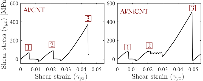
During the initial relaxation step, the dislocation reduces its energy by migrating towards the CNT: once the part of the dislocation which intersects the void surrounding the CNT disappears, the dislocation line energy decreases. Upon loading, the imposed shear deformation creates a shear stress in the sample which, in turn, exerts a configurational force (Peach-Koehler-force) that drives the dislocation to move in the positive direction. Because of the attractive force between the dislocation and the CNT, the dislocation remains first attached to the CNT until, at a critical stress, it breaks free. This process is indicated by a sudden load drop on the stress-strain curves (marked 1 in Fig. 3 which shows shear stress-strain curves for Al/CNT and Al/NiCNT systems with = 368 and = 28 ). For systems containing many dislocations and CNTs with comparable geometrical arrangement, the stress before this load drop may be interpreted as the critical resolved shear stress (CRSS).
Due to the periodic boundary conditions imposed in slip direction, a dislocation can move mulitple times through the simulated sample and interact with the embedded CNT. While this appears at first glance unphysical, the situation can be understood as a simulation of multiple dislocations emitted from the same source and sequentially interacting with the CNT. During these interactions, the conformations of both the dislocation and Al atoms surrounding the CNT, though not of the CNT itself, undergo characteristic changes which lead to characteristic signatures in the stress-strain curves. The situation may be discussed in analogy with precipitation-hardened materials where for shearable precipitates the cutting of a precipitate by multiple dislocations moving on the same slip plane can lead to softening: the passing stress is reduced as the number of dislocations cutting the precipitates increases, and in some cases the precipitates may even dissolve [43]. For non-shearable precipitates, on the other hand, the deposition of Orowan loops around the precipitates may lead to strain hardening.
In the following we first investigate the dependency of the CRSS on CNT diameter and spacing, and then investigate the hardening mechanisms associated with multiple dislocations passing a CNT.
3.1 Effect of CNT diameter and spacing on CRSS
In this part, we investigate the dependency of the CRSS on the CNT diameter and spacing . Table 1 details the simulation box sizes and CNT diameters. Our MD simulation results show that an increase of the CNT diameter results in an increase of CRSS, which can be described by a logarithmic CRSS dependence on , see Fig. 4 (a). At the same time, the CRSS changes in approximately inverse proportion with the CNT spacing as shown in Fig. 4 (b).
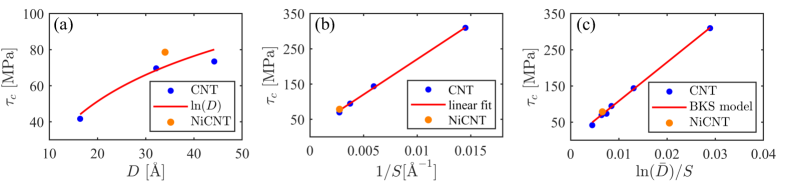
Our observations can be well represented by the model proposed by Bacon et al. [44] for the interaction of a dislocation with an array of non-shearable precipitates, henceforth referred to as BKS model. This model has been validated for precipitation hardening in metallic alloys by experimental and numerical analysis ([14, 5, 12, 6, 23]). The model predicts that the critical stress for a dislocation required to pass a periodic array of non-shearable inclusions is given by
| (3) |
where is the shear modulus, is the harmonic mean of the spacing and diameter of the inclusions, divided by the Burgers vector magnitude : . is a nondimensional parameter which depends on dislocation type and is equal to 1 for an edge dislocation, and is an adjustable variable. Using values for Al i.e. and = 28 GPa, we find that our MD data are very well represented by the BKS model, see Fig. 4 (c). For an edge dislocation in aluminum gliding in an (111) plane the pre-factor of the above formula is equal to = 12.7 (GPa ). This value is in good agreement with the slope of a straight line fitted to the MD data of versus , which is 11.4 (GPa). Note that the CRSS values are comparable for coated and uncoated CNTs, provided that the diameter of the Ni coated CNT is taken to be the outer diameter of the coating.
We thus conclude that, as far as the CRSS is concerned, the embedded CNTs irrespective of coating status behave like non-shearable precipitates. However, when it comes to hardening effects, there are characteristic differences from the classical picture of dislocations by-passing non-shearable obstacles by depositing Orowan loops around them. The hardening mechanisms associated with multiple dislocations passing a CNT on the same slip plane are analyzed in the following.
3.2 Mechanisms of dislocation-CNT interaction
To discuss the detailed processes occurring upon encounter between the moving dislocation and the CNT, we measure the area swept by the moving dislocation, starting from its equilibrium configuration where it is aligned with the CNT in the configuration. We measure this area in terms of the parameter , for instance, a dislocation that bows out into a perfect half-circular shape in the configuration would correspond to .
3.2.1 Pristine CNT, first encounter
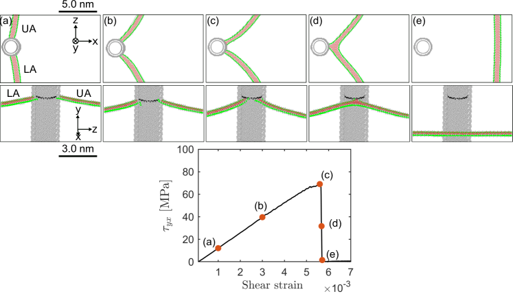
Fig. 5 shows the first encounter of a dislocation with a pristine CNT(20,20) ( = 28 , = 368 ) in top and front views. In this figure, we only depict atoms with non-fcc crystal environment for clarity. Fig. 5 (a-d) shows that the dislocation segments on both sides of the CNT move in direction to accommodate the shear displacement while the points of intersection between the CNT and the dislocation move around the CNT. This motion is concomitant with a rotation of the upper and lower arms of the dislocation. Once the leading partials of both arms have rotated by an angle close to around the CNT, they merge upon encounter (Fig. 5 (d)). The dislocation then detaches from the CNT, leaving behind a step of height in the cylindrical Al surface surrounding the void. This step is accommodated by elastic deformation of the embedded CNT.
3.2.2 Second encounter
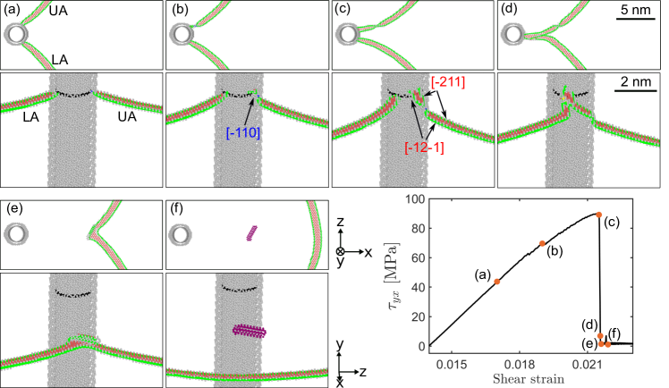
During the second encounter, the dislocation is first attracted towards the CNT and passes a minimum energy configuration where it aligns near-perpendicularly with the CNT in configuration. Under increasing shear stress, both dislocation arms again start to rotate and the points of intersection migrate around the CNT. However, accomplishing a full quarter circle to the orientation is associated with a prohibitive energy cost since the elastic energy of the created surface step, which must internally be accommodated by a S-shaped bending of the embedded CNT, scales in proportion with the square of the step height. Therefore, the movement of the intersection points is impeded (Fig. 6 (a)) and the two dislocation arms reach the screw orientation before the intersection points have reached the location where the arms could merge. Instead, once the upper intersection point has reached (Fig. 6 (b)), the upper arm is already in near-screw orientation. This allows the dislocation to avoid the obstacle presented by the surface step deposited in the previous encounter through a double cross-slip process: the arm constricts at the intersection points, cross slips, and re-dissociates on a parallel slip plane above the original one, thus avoiding the pre-existing slip step (Fig. 6 (c)). The intersection point of this arm has now acquired increased mobility and travels around the CNT beyond the location to reach the lower arm (Fig. 6 (d)), where both arms annihilate via a second cross slip event. This annihilation detaches the dislocation, which in the process has acquired a double jog (Fig. 6 (e)). This double jog is finally left behind in form of a prismatic dislocation loop (Fig. 6 (f)).
3.2.3 Third encounter
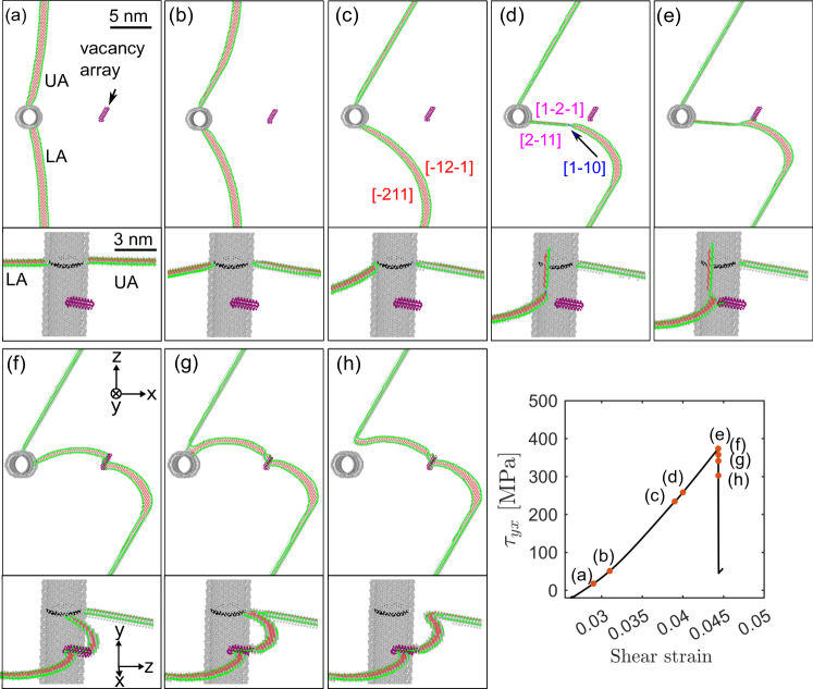
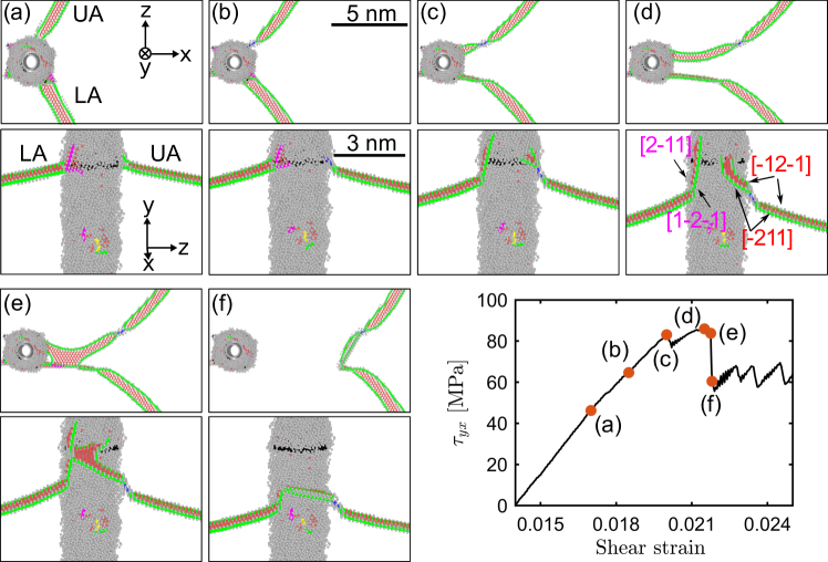
Fig. 7 show the process of dislocation unpinning from the CNT for the third time in top and front view. As a result of the previous two encounters, there is now an asymmetry between the upper and lower arms of the dislocation as the intersection between the two slip steps deposited by the upper arm on the CNT-Al interface acts as a very strong pinning point that cannot be passed by the upper arm, which can neither proceed on the original slip plane nor pass onto the cross slip plane (Fig. 7 (a)). Instead, the partials of the upper arm rotate around their intersection points and, once it reaches the orientation, the leading partial – which is at that moment in screw orientation – cross slips to create a non-planar core configuration akin to a Lomer-Cottrell lock (Fig. 7 (b)). The lock then expands along the upper arm and locks it in orientation (Fig. 7 (c)).
The lower arm, on the other hand, undergoes very much the same scenario as the upper arm did in the second encounter: The intersection point moves around the CNT, but its motion is impeded by the previously formed slip step. The arm thus rotates into near screw orientation () which is reached when the intersection point is located near (Fig. 7 (c)). The lower arm then constricts at the intersection point, cross slips and re-dissociates on the cross slip plane. This process restores the mobility of the intersection points which move along the intersection of the CNT with the cross slip plane (Fig. 7 (d,e)). At the same time, the non-cross slipped part of the lower arm continues to rotate until it gets pinned by the prismatic loop that has been left behind from the second dislocation-CNT interaction (Fig. 7 (e)). The constriction separating the cross slipped and non cross slipped parts of the lower arm also migrates towards the prismatic loop and the interaction causes the cross slipped part to revert to the original slip plane (Fig. 7 (f)). This part of the lower arm starts rotating around the CNT again, until it eventually meets the upper arm, detaches it from the CNT and unzips the lock (Fig. 7 (g,h)).
We note that the process described here is contingent on interaction of the dislocation with the previously deposited prismatic loop and can therefore not occur in the same form when multiple dislocations interact with a CNT in a non-periodic system. While this might lead one to consider the entire process an artefact, we note that a very similar scenario which does not involve debris from previous passes is observed with Ni-coated CNTs. This will be described in the following.
The CRSS for the second passage is slightly higher than the first passage. On the other hand, the third passage requires much higher stress as shown in Fig. 3.
3.3 Dislocation NiCNT interaction
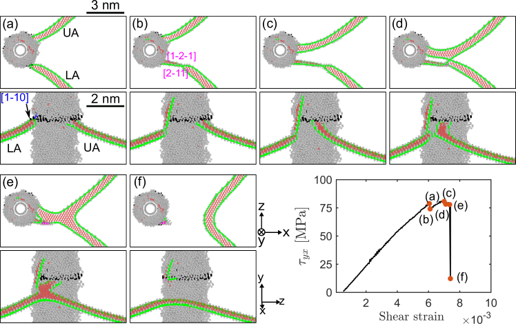
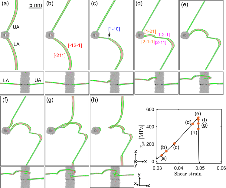
Next, we analyze the dislocation passing mechanisms for a Ni-coated CNT, again considering three sequential CNT-dislocation encounters. The main features of these encounters are similar to the case of a pristine CNT. However, the large elastic mismatch between Al and Ni increases the energy associated with a slip step in the surface of the cylinder surrounding the CNT interface, which now is doubled up by a step in the interface between Al matrix and Ni coating. As a consequence, migration of the dislocation intersection point around the CNT is impeded already during the first encounter. Thus, the lower arm reaches the orientation, constricts and passes on the cross slip plane when its intersection point with the Ni coating is still at . The cross slipped part then expands on the cross-slip plane while the constriction point travels along the intersection of the primary and cross slip planes. At the same time, the attractive interaction between upper and lower arms helps the upper arm to travel around the CNT until it reaches the non-cross slipped part of the lower arm and annihilates (Fig. 8 (e)). This process detaches the dislocation from the CNT, leaving behind a non-planar half dislocation loop which is deposited at the NiCNT-Al interface.
During the second encounter between NiCNT and dislocation the lower arm again passes on a cross slip plane (Fig. 9 (a)). However, the motion of the upper arm is modified since now the pre-existing slip step prevents its motion around the CNT on the original slip plane. Instead, the upper arm undergoes a non-crystallographic double cross slip event (Fig. 9 (b,c)) which takes it to a parallel slip plane. The double-cross-slipped segment then travels around the CNT (Fig. 9 (d)) until it reaches the cross-slipped segment of the lower arm and the mutual attraction of both segments causes the latter to reverse its motion and annihilate (Fig. 9 (e)), thus detaching the dislocation (Fig. 9 (f)). In the process the dislocation again acquires a double jog. The stress-strain curve of the AlNiCNT system shows (Fig. 3) that despite the unpinning from the NiCNT, the shear stress does not drop significantly. This is because of the presence of the super jog on the dislocation, which requires much energy to glide. Eventually, the dislocation leaves behind the double jog in form of a prismatic dislocation loop and reverts to a planar configuration.
The scenario during the third encounter with the NiCNT closely resembles the findings in case of a pristine CNT: The upper arm – now strongly pinned by the slip step and debris left behind from the previous encounters – undergoes cross slip of the leading partial once it reaches the configuration and as a consequence transforms into a lock (Fig. 10 (a,b)). The lower arm constricts at the intersection point with the Ni coating and expands on its cross-slip plane while the constriction point travels along the intersection line of primary and cross slip plane (Fig. 10 (c)). Ultimately, the cross slipped segment undergoes a second cross slip event and passes onto a slip plane parallel to the primary one (Fig. 10 (c,d)), where it rotates around the Ni-coated CNT (Fig. 10 (e)) and ultimately approaches the locked upper arm. The repulsive interaction between the leading partials of upper and lower arms then causes the leading partial of the upper arm to revert to its original glide plane, the lock becomes unzipped and the upper arm is re-mobilized (Fig. 10 (f)). Finally, a cross slip event of the upper arm (Fig. 10 (g)) causes the upper and lower arms to merge and detach from the CNT (Fig. 10 (h)), leaving the dislocation with a double super-jog. We note that this process is generic in the sense that it does not involve any dislocation debris.
4 Discussion and conclusions
We have studied the interactions of edge dislocations with pristine and Ni-coated CNT in Al matrices. These obstacles are found to behave in a manner that is, in a sense, intermediate between non-shearable and shearable precipitates. While the CRSS dependency on CNT diameter and spacing is well described by relations derived originally for non-shearable precipitates, the details of the interaction mechanism differ significantly from a simple Orowan mechanism. This is particularly true for multiple dislocations passing the obstacle on the same slip plane. While the CNT in itself is not shearable, the cylindrical void surrounding the CNT can be sheared at the expense of forming an interfacial slip step in conjunction with elastic deformation of the CNT. This configuration acts as an obstacle to subsequent dislocations – an effect that is enhanced by Ni coating of the CNT. Second and third dislocations passing the CNT on the same slip plane therefore require increasing shear stresses to overcome the obstacle, i.e., the sequential interaction of multiple dislocations with an embedded CNT leads to strain hardening, quite unlike precipitate shearing which may lead to softening or even dissolution of the precipitates. However, the hardening scenario is also quite different from the classical Orowan scenario which envisages the deposition of multiple dislocation loops around non-shearable precipitates. The scenario observed here is much more complex and involves crystallographic and non-crystallographic cross slip of near-screw segments on the CNT-metal interface, dislocation lock formation and annihilation, jog formation and shedding of prismatic dislocation loops. We note, however, that elements of this scenario have been observed in other MD simulations of dislocation-obstacle interactions, see e.g. the observation of double jog formation during passing of a hard precipitate by an edge dislocation in Ni as reported in [19], or the formation of jogs during interaction of edge dislocations in Fe with voids and He bubbles as reported in [45].
Acknowledgments
SN and MZ acknowledge financial support from DFG under grant no. Za171/11-1. The authors would like to thank Erik Bitzek, Julien Guénolé and Aviral Vaid for discussion and insights regarding atomistic simulation of dislocations in metals. The authors gratefully acknowledge the compute resources and support provided by the Erlangen Regional Computing Center (RRZE).
Conflict of Interest
The authors declare that they have no known competing financial interests or personal relationships that could have appeared to influence the work reported in this paper.
References
- [1] C. Lee, X. Wei, J. W. Kysar, J. Hone, Measurement of the elastic properties and intrinsic strength of monolayer graphene, Science 321 (5887) (2008) 385–388. doi:10.1126/science.1157996.
- [2] V. N. Popov, V. E. V. Doren, M. Balkanski, Elastic properties of single-walled carbon nanotubes, Physical Review B 61 (4) (2000). doi:10.1103/physrevb.61.3078.
- [3] M. Yu, Strength and breaking mechanism of multiwalled carbon nanotubes under tensile load, Science 287 (5453) (2000) 637–640. doi:10.1126/science.287.5453.637.
- [4] S. Nasiri, M. Zaiser, Rupture of graphene sheets with randomly distributed defects, AIMS materials science 3 (4) (2016) 1340–1349. doi:10.3934/matersci.2016.4.1340.
- [5] R. George, K. Kashyap, R. Rahul, S. Yamdagni, Strengthening in carbon nanotube/aluminium (CNT/al) composites, Scripta Materialia 53 (10) (2005) 1159–1163. doi:10.1016/j.scriptamat.2005.07.022.
- [6] Q. Li, A. Viereckl, C. A. Rottmair, R. F. Singer, Improved processing of carbon nanotube/magnesium alloy composites, Composites Science and Technology 69 (7-8) (2009) 1193–1199. doi:10.1016/j.compscitech.2009.02.020.
- [7] S. R. Bakshi, D. Lahiri, A. Agarwal, Carbon nanotube reinforced metal matrix composites - a review, International Materials Reviews 55 (1) (2010) 41–64. doi:10.1179/095066009x12572530170543.
- [8] S. Nasiri, K. Wang, M. Yang, Q. Li, M. Zaiser, Nickel coated carbon nanotubes in aluminum matrix composites: a multiscale simulation study, The European Physical Journal B 92 (8) (2019). doi:10.1140/epjb/e2019-100243-6.
- [9] B. Chen, S. Li, H. Imai, L. Jia, J. Umeda, M. Takahashi, K. Kondoh, Load transfer strengthening in carbon nanotubes reinforced metal matrix composites via in-situ tensile tests, Composites Science and Technology 113 (2015) 1–8. doi:10.1016/j.compscitech.2015.03.009.
- [10] B. Chen, J. Shen, X. Ye, L. Jia, S. Li, J. Umeda, M. Takahashi, K. Kondoh, Length effect of carbon nanotubes on the strengthening mechanisms in metal matrix composites, Acta Materialia 140 (2017) 317–325. doi:10.1016/j.actamat.2017.08.048.
- [11] B. Chen, K. Kondoh, J. Umeda, S. Li, L. Jia, J. Li, Interfacial in-situ al2o3 nanoparticles enhance load transfer in carbon nanotube (CNT)-reinforced aluminum matrix composites, Journal of Alloys and Compounds 789 (2019) 25–29. doi:10.1016/j.jallcom.2019.03.063.
- [12] D. M. Park, J. H. Kim, S. J. Lee, G. H. Yoon, Analysis of geometrical characteristics of cnt-al composite using molecular dynamics and the modified rule of mixture (mrom), Journal of Mechanical Science and Technology 32 (12) (2018) 5845–5853. doi:10.1007/s12206-018-1133-5.
- [13] N. Silvestre, B. Faria, J. N. C. Lopes, Compressive behavior of cnt-reinforced aluminum composites using molecular dynamics, Composites Science and Technology 90 (2014) 16–24. doi:10.1016/j.compscitech.2013.09.027.
- [14] B. K. Choi, G. H. Yoon, S. Lee, Molecular dynamics studies of CNT-reinforced aluminum composites under uniaxial tensile loading, Composites Part B: Engineering 91 (2016) 119–125. doi:10.1016/j.compositesb.2015.12.031.
- [15] J. Xiang, L. Xie, S. A. Meguid, S. Pang, J. Yi, Y. Zhang, R. Liang, An atomic-level understanding of the strengthening mechanism of aluminum matrix composites reinforced by aligned carbon nanotubes, Computational Materials Science 128 (2017) 359–372. doi:10.1016/j.commatsci.2016.11.032.
- [16] Q. Li, C. A. Rottmair, R. F. Singer, Cnt reinforced light metal composites produced by melt stirring and by high pressure die casting, Composites Science and Technology 70 (16) (2010) 2242–2247. doi:10.1016/j.compscitech.2010.05.024.
- [17] K. P. So, X. Liu, H. Mori, A. Kushima, J. G. Park, H. S. Kim, S. Ogata, Y. H. Lee, J. Li, Ton-scale metal-carbon nanotube composite: The mechanism of strengthening while retaining tensile ductility, Extreme Mechanics Letters 8 (2016) 245–250. doi:10.1016/j.eml.2016.04.002.
- [18] D. Lahiri, S. Bakshi, A. Keshri, Y. Liu, A. Agarwal, Dual strengthening mechanisms induced by carbon nanotubes in roll bonded aluminum composites, Materials Science and Engineering: A 523 (1-2) (2009) 263–270. doi:10.1016/j.msea.2009.06.006.
- [19] L. Proville, B. Bakó, Dislocation depinning from ordered nanophases in a model fcc crystal: From cutting mechanism to orowan looping, Acta Materialia 58 (17) (2010) 5565 – 5571. doi:10.1016/j.actamat.2010.06.018.
- [20] D. Terentyev, D. J. Bacon, Y. N. Osetsky, Interaction of an edge dislocation with voids in -iron modelled with different interatomic potentials, Journal of Physics: Condensed Matter 20 (44) (2008) 445007. doi:10.1088/0953-8984/20/44/445007.
- [21] D. Terentyev, L. Malerba, G. Bonny, A. Al-Motasem, M. Posselt, Interaction of an edge dislocation with cu–ni-vacancy clusters in bcc iron, Journal of Nuclear Materials 419 (1) (2011) 134 – 139. doi:10.1016/j.jnucmat.2011.08.021.
- [22] A. Prakash, J. Guénolé, J. Wang, J. Müller, E. Spiecker, M. Mills, I. Povstugar, P. Choi, D. Raabe, E. Bitzek, Atom probe informed simulations of dislocation–precipitate interactions reveal the importance of local interface curvature, Materialia 92 (2015) 33 – 45. doi:10.1016/j.actamat.2015.03.050.
- [23] A. Vaid, J. Guénolé, A. Prakash, S. Korte-Kerzel, E. Bitzek, Atomistic simulations of basal dislocations in mg interacting with mg17al12 precipitates, Materialia 7 (2019) 100355. doi:10.1016/j.mtla.2019.100355.
- [24] G. Bonny, A. Bakaev, D. Terentyev, Assessment of hardening due to non-coherent precipitates in tungsten-rhenium alloys at the atomic scale, Scientific Reports 9 (1) (Nov 2019). doi:10.1038/s41598-019-52521-x.
- [25] D. Bacon, Y. Osetsky, D. Rodney, Chapter 88 dislocation–obstacle interactions at the atomic level, in: J. Hirth, L. Kubin (Eds.), Dislocations in Solids, Vol. 15 of Dislocations in Solids, Elsevier, 2009, pp. 1 – 90. doi:10.1016/s1572-4859(09)01501-0.
- [26] Y. Kim, J. Lee, M. S. Yeom, J. W. Shin, H. Kim, Y. Cui, J. W. Kysar, J. Hone, Y. Jung, S. Jeon, et al., Strengthening effect of single-atomic-layer graphene in metal–graphene nanolayered composites, Nature communications 4 (2013) ncomms3114. doi:10.1038/ncomms3114.
- [27] S.-W. Chang, A. K. Nair, M. J. Buehler, Nanoindentation study of size effects in nickel–graphene nanocomposites, Philosophical Magazine Letters 93 (4) (2013) 196–203. doi:10.1080/09500839.2012.759293.
- [28] X. Liu, F. Wang, W. Wang, H. Wu, Interfacial strengthening and self-healing effect in graphene-copper nanolayered composites under shear deformation, Carbon 107 (2016) 680–688. doi:10.1016/j.carbon.2016.06.071.
- [29] S. Plimpton, Fast parallel algorithms for short-range molecular dynamics, Journal of computational physics 117 (1) (1995) 1–19. doi:10.1006/jcph.1995.1039.
- [30] P. Hirel, Atomsk: A tool for manipulating and converting atomic data files, Computer Physics Communications 197 (2015) 212–219. doi:10.1016/j.cpc.2015.07.012.
- [31] J. Schneider, J. Hamaekers, S. T. Chill, S. Smidstrup, J. Bulin, R. Thesen, A. Blom, K. Stokbro, Atk-forcefield: a new generation molecular dynamics software package, Modelling and Simulation in Materials Science and Engineering 25 (8) (2017) 085007. doi:10.1088/1361-651x/aa8ff0.
- [32] D. Stradi, L. Jelver, S. Smidstrup, K. Stokbro, Method for determining optimal supercell representation of interfaces, Journal of Physics: Condensed Matter 29 (18) (2017) 185901. doi:10.1088/1361-648x/aa66f3.
- [33] A. Stukowski, Visualization and analysis of atomistic simulation data with ovito-the open visualization tool, Modelling and Simulation in Materials Science and Engineering 18 (1) (2010). doi:10.1088/0965-0393/18/1/015012.
- [34] D. Faken, H. Jónsson, Systematic analysis of local atomic structure combined with 3d computer graphics, Computational Materials Science 2 (2) (1994) 279–286. doi:10.1016/0927-0256(94)90109-0.
- [35] J. D. Honeycutt, H. C. Andersen, Molecular dynamics study of melting and freezing of small lennard-jones clusters, The Journal of Physical Chemistry 91 (19) (1987) 4950–4963. doi:10.1021/j100303a014.
- [36] D. W. Brenner, O. A. Shenderova, J. A. Harrison, S. J. Stuart, B. Ni, S. B. Sinnott, A second-generation reactive empirical bond order (rebo) potential energy expression for hydrocarbons, Journal of Physics: Condensed Matter 14 (4) (2002) 783. doi:10.1088/0953-8984/14/4/312.
- [37] S. J. Stuart, A. B. Tutein, J. A. Harrison, A reactive potential for hydrocarbons with intermolecular interactions, The Journal of chemical physics 112 (14) (2000) 6472–6486. doi:10.1063/1.481208.
- [38] Y. Mishin, Atomistic modeling of the and -phases of the ni–al system, Acta Materialia 52 (6) (2004) 1451–1467. doi:10.1016/j.actamat.2003.11.026.
- [39] E. Bitzek, P. Koskinen, F. Gähler, M. Moseler, P. Gumbsch, Structural relaxation made simple, Phys. Rev. Lett. 97 (2006) 170201. doi:10.1103/PhysRevLett.97.170201.
- [40] Q. Li, S. Fan, W. Han, C. Sun, W. Liang, Coating of carbon nanotube with nickel by electroless plating method, Japanese Journal of Applied Physics 36 (Part 2, No. 4B) (1997) L501–L503. doi:10.1143/jjap.36.l501.
- [41] F. Kong, X. Zhang, W. Xiong, F. Liu, W. Huang, Y. Sun, J. Tu, X. Chen, Continuous ni-layer on multiwall carbon nanotubes by an electroless plating method, Surface and Coatings Technology 155 (1) (2002) 33 – 36. doi:10.1016/S0257-8972(02)00032-4.
- [42] A. P. Thompson, S. J. Plimpton, W. Mattson, General formulation of pressure and stress tensor for arbitrary many-body interaction potentials under periodic boundary conditions, The Journal of Chemical Physics 131 (15) (2009) 154107. doi:10.1063/1.3245303.
- [43] C. Hutchinson, P. T. Loo, T. J. Bastow, A. Hill, J. da Costa Teixeira, Quantifying the strain-induced dissolution of precipitates in al alloy microstructures using nuclear magnetic resonance, Acta materialia 57 (19) (2009) 5645–5653. doi:10.1016/j.actamat.2009.07.060.
- [44] D. J. Bacon, U. F. Kocks, R. O. Scattergood, The effect of dislocation self-interaction on the orowan stress, Philosophical Magazine 28 (6) (1973) 1241–1263. doi:10.1080/14786437308227997.
- [45] S. Hafez Haghighat, R. Schäublin, Influence of the stress field due to pressurized nanometric he bubbles on the mobility of an edge dislocation in iron, Philosophical Magazine 90 (7-8) (2010) 1075–1100. doi:10.1080/14786431003630801.