Kinetics of ion migration in the electric field-driven manipulation of magnetic anisotropy of Pt/Co/oxide multilayers
Abstract
Magneto-ionics, by which the magnetic properties of a thin layer can be modified through the migration of ions within a liquid or solid electrolyte, is a fast developing research field. This is mainly due to the perspective of energy efficient magnetic devices, in which the magnetization direction is controlled not by a magnetic field or an electrical current, as done in traditional devices, but by an electric field, leading to a considerable reduction of energy consumption.
In this work, the interfacial perpendicular magnetic anisotropy (PMA) of a series of Pt/Co/oxide trilayers covered by a ZrO2 layer, acting as a ionic conductor, was finely tuned by a gate voltage at room temperature. The non-volatility and the time evolution of the effect point at oxygen ion migration across the ZrO2 layer as the driving mechanism. A large variation of the PMA is obtained by modifying the degree of oxidation of the cobalt layer with the flux of oxygen ions: the easy magnetization axis can be switched reversibly from in-plane, with an under-oxidized Co, to in-plane, with an over-oxidized Co, passing through an out-of-plane magnetization with maximum PMA. The switching time between the different magnetic states is limited by the oxygen ion drift velocity through the multilayer structure. This was shown to depend exponentially on the applied bias voltage, and could be varied by over 5 orders of magnitude, from several minutes to a few ms. On the other hand, for a fixed gate-voltage, the oxidation of the cobalt layer decreases exponentially as a function of time. This behavior is in agreement with the theoretical model developed by Cabrera and Mott (1949) to explain the growth of very thin oxides at low temperatures. The possibility to explain the observed effect with a relatively simple theoretical model opens the possibility to engineers materials with optimized properties.
keywords:
magneto-ionics, voltage control of magnetic anisotropy, magnetic thin films, perpendicular magnetic anisotropy, magnetization switchingAymen Fassatoui, Laurent Ranno, Jose Peña Garcia, Cristina Balan, Jan Vogel, Hélène Béa, Stefania Pizzini*
Aymen Fassatoui, Laurent Ranno, Jose Peña Garcia, Cristina Balan, Jan Vogel, Stefania Pizzini
Univ. Grenoble Alpes, CNRS, Institut Néel, Grenoble, France
Hélène Béa
Univ. Grenoble Alpes, CEA, CNRS, Grenoble INP, IRIG-SPINTEC, Grenoble, France
* stefania.pizzini@neel.cnrs.fr
1 Introduction
Voltage control of magnetic properties, and in particular magneto-ionics, is receiving a growing interest as it opens the possibility to largely improve the energetic efficiency of magnetic memories and other spintronic devices [1]. Perpendicular magnetic anisotropy (PMA) is a key property of ultrathin magnetic films, as its strength determines the preferred orientation of their magnetization. The possibility to manipulate the PMA is therefore a key requirement for the conception of such devices.
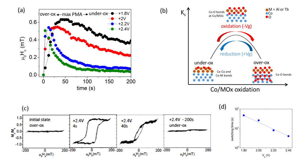
PMA in thin ferromagnetic (FM) films is generally observed at interfaces with a heavy metal with large spin-orbit interaction, like Pt/Co, but surprisingly also at FM-oxide interfaces [2]. This is attributed to the hybridization between the metal and the oxygen electronic orbitals across the interfaces, as confirmed by ab initio calculations [3]. The amplitude of this interaction is strongly sensitive to the degree of oxidation of the metal/oxide interface. In Pt/FM/MOx stacks, the maximum PMA is obtained for the optimal oxidation of the FM/oxide interface, when all the metal interfacial FM atoms being bonded to oxygen atoms. If the contribution of the Pt/FM interface to the PMA is not sufficient to promote out-of-plane magnetization, a slight increase or decrease of the oxidation (towards an over- or under-oxidized state) may be sufficient to switch the magnetization from out-plane (OOP) to in-plane (IP) (see Figure 3(b)) [4, 5, 6, 7].
The interfacial anisotropy at the FM-oxide interface can be manipulated by an electric field via electronic [8, 9, 10] or magneto-ionic effects [1]. The largest effects of the electric field on the PMA were obtained by triggering the oxidation of cobalt via the migration of oxygen ions [11, 12, 13]. Up to recent years, this mechanism was observed to be slow and to require high temperatures, since the voltage-driven switching between IP and OOP magnetization was shown to require several minutes at room temperature [11]. A voltage-driven mechanism in which the modification of interfacial PMA is attributed to the migration of hydrogen, rather than to the heavier oxygen ions, was recently proposed as a more efficient [14, 15] and faster (down to 2 ms) [16] way to switch the magnetization.
In this work, we show that by depositing on top of the magnetic stack a thin ZrO2 layer acting as an oxygen ion conductor, a huge voltage-driven variation of the PMA can be obtained for two model systems for spintronic applications, Pt/Co/AlOx and Pt/Co/TbOx trilayers. While Pt/Co/AlOx [Miron2011] was the first system in which chiral domain walls could be driven efficiently by spin-orbit torque, Pt/Co/TbOx may be interesting as The mechanism, driven by oxygen ion migration that tunes the oxidation of the Co layer, is non-volatile, reversible, and relatively robust. The switching time between OOP and IP magnetic state depends exponentially on the applied bias voltage, and in Pt/Co/AlOx it was decreased by over 5 orders of magnitude (from several minutes to a few ms) by increasing the bias voltages from 1 V and 6 V.
The temporal variation of the interfacial anisotropy in the presence of an applied gate voltage can be modeled by assuming a parabolic variation of the PMA versus the oxidation rate, and an exponential variation of the oxidation/reduction of the cobalt layer versus time. The temporal variation of the oxidation rate is in agreement with the theory proposed by Cabrera and Mott in 1949 [17] for the formation of a thin oxide film, which occurs under the effect of the large electric field due to the contact potential difference at the oxide/metal interface.
2 Experimental details
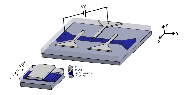
Pt(4)/Co(1.1 to 1.2)/TbOx(0.6) and Pt(4)/Co(0.6)/AlOx(1) magnetic stacks were deposited by magnetron sputtering on Si/SiO2 wafers (see also [18]). After patterning the films into 1-m, 2-m and 5-m wide strips by electron beam lithography (EBL) and ion-beam etching, a 10 nm thick ZrO2 dielectric layer was deposited by atomic layer deposition (ALD). The oxide layer, grown at 100°C, has an amorphous structure. Finally, 6 nm thick Pt electrodes were patterned by EBL and lift-off, acting as local gates (Figure 1). To study the time evolution of the PMA during the application of the gate voltage, hysteresis loops were recorded using a polar magneto-optical Kerr magnetometer, with the light focused on the gate electrode. The magnetic configuration of some of the magnetic stacks was measured by magnetic force microscopy (MFM).
3 Non volatile manipulation of the PMA in Pt/Co/TbOx stacks
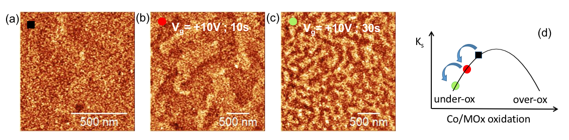
The magnetization configuration of Pt/Co(1.2)/TbOx was observed by MFM both in the as-patterned state, characterised by a saturated out-of-plane magnetization with an under-oxidized Co layer, and after the application of a constant bias voltage of +10 V for 10 s and 30 s, at room temperature. Each image was taken with a closed circuit, after the removal of the bias voltage. The three images are shown in Figure 2(a-c).
In the initial state, the MFM image (Figure 2(a)) shows as expected a homogeneous contrast. When the bias field is applied for 10 s (Figure 2(b)), labyrinthine magnetic domains appear, with an average width of the order of 400 nm. When the same positive voltage is applied for 20 more seconds (Figure 2(c)) the width of the magnetic domains decreases to around 100 nm. Since the formation of a demagnetized state reveals that the systems is close to the re-orientation transition between OOP and IP magnetization, our results show that the positive voltage leads to a decrease of the PMA.
The labyrinthine domain width in the case of ultrathin ferromagnetic layers is given by [19, 20] , where is the characteristic dipolar length, is the domain wall energy, is the ferromagnetic film thickness and is a numerical constant of the order of 1. In the non-centrosymmetric stacks studied in this work, domain walls have chiral Néel structure [21, 22] and their energy is given by , where is the exchange stiffness and is the strength of the Dzyaloshinskii-Moriya interaction. The domain width then depends exponentially on the domain wall energy, and therefore on the effective magnetic anisotropy. The observed decrease of the domain size for increasing duration of the applied bias reflects the progressive decrease of the interfacial PMA.
The domain width observed in Figs. 2 (b,c) does not evolve during the MFM scan time (8 minutes) and for several days after the application of the voltage: we then define the magnetic state obtained after the application of the bias voltage as non-volatile. As already illustrated by our previous work [18], the cumulative and non-volatile variation of the magnetic anisotropy leads us to exclude charge accumulation/depletion effects and to suggest that the voltage-driven migration of oxygen ions is the most probable driving mechanism. Since a positive bias drives oxygen ions away from the Co layer, this leads to a decrease of its oxidation which causes a decrease of the PMA (see sketch in Figure 2(d)).
4 Large tuning of interfacial anisotropy
The results just described show that the magnetic anisotropy can be finely tuned by adjusting the application time of the bias voltage and therefore the oxidation of the cobalt layer. Based on the results of previous investigations on Pt/Co/oxide systems [2, 4, 5, 6, 7] we anticipate that the voltage-driven migration of oxygen ions might be used to tune the magnetization from IP (for an under-oxidized Co) to IP (for an over-oxidized Co) passing through a state with maximum PMA (see sketch in Figure 3(b)).
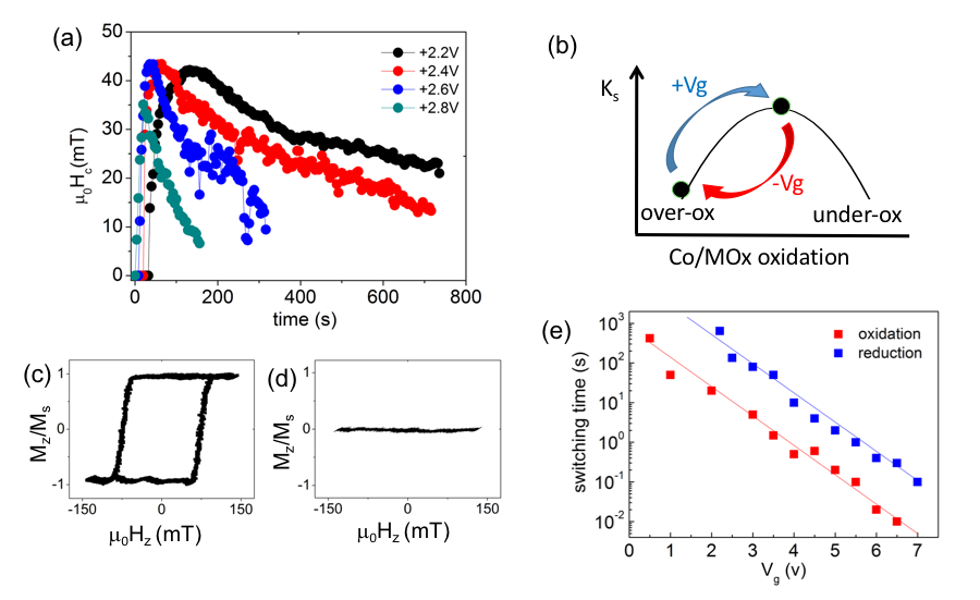
This was partially achieved by Bi et al. [11] for Pt/Co/Gd2O3 stacks where the electric field was applied at high temperature (260°C) and for long times (up to 600 s). Our results are shown in Figure 3(a) for a Pt/Co(1.1)/TbOx 5x5 capacitor-like structure. (Note that in this stack the Co layer is slightly thinner than in the one described in the previous section). Starting from an over-oxidized state with IP magnetization, the time evolution of the coercive field was measured during the application of several positive bias voltages Vg (from +1.8 V to +2.4 V) which reduces the Co layer. Each point in the curve represents the average coercivity measured over 4 hysteresis cycles, each taking 1 second. In these curves, the variation of reflects the variation of the anisotropy at the Co/oxide interface [23], so we will discuss the results in terms of the PMA. For each bias voltage, the PMA first increases, so that the magnetization switches from IP to OOP, passes through a maximum (optimum oxidation) and eventually decreases as the Co interface becomes under-oxidized and the magnetization turns in-plane (as shown by the hysteresis cycles in Figure 3(c) and sketched in Figure 3(b)). A large change of the interfacial anisotropy (estimated 6000 fJ/(Vm)) is therefore obtained using reversible oxygen ion migration at room temperature as the driving mechanism.
For each bias voltage Vg, the transition between the initial IP over-oxidized state and the maximum PMA state is faster than the transition between the maximum PMA state and under-oxidized IP state. The two transition times decrease exponentially with the bias voltage amplitude, as shown in Figure 3(d) for the IP (over-oxidized state) to the OOP state with maximum PMA. By increasing the bias voltage from +1.8 V to +2.4 V, the switching time at room temperature decreases from 48 s to 4 s. As will be discussed later, this behaviour is in agreement with an exponential increase of the drift velocity of oxygen ions versus Vg expected for the very large electric fields used in this work [24].
5 Stability of the under-oxidized magnetic state and spontaneous re-oxidation
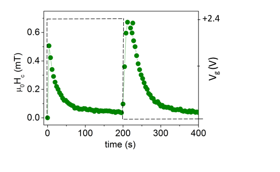
When the positive bias voltage is removed after reaching an under-oxidized state with IP magnetization, our measurements on the Pt/Co(1.1)/TbOx stack suggest the occurring of a spontaneously re-oxidation of the Co top interface. This is shown in Figure 4 where we present the temporal evolution of the coercive field after the removal of the bias voltage Vg=+2.4V, applied for t=200 s. Starting from the IP magnetization (under-oxidized state induced by the application of the positive gate voltage), the coercivity (and therefore the PMA) is observed to quickly increase, to reach a maximum and then to decrease and vanish. The final equilibrium state of the system is characterised by an over-oxidized Co layer with IP magnetization.
This behavior is different from the one obtained for the Pt/Co(1.2)/TbOx stack described above (Figure 2), where the stripe domain structure in the under-oxidized state was observed to be stable over a long time. The two Pt/Co/TbOx stacks, grown simultaneously with a Co thickness gradient, differ only for the slight variation of the Co thickness. The labyrinthine structure characterising the demagnetized state is obtained when , where and are respectively the interfacial magnetic anisotropies at the Pt/Co and Co/oxide interfaces. The critical satisfying this condition decreases as decreases. Therefore, a stripe domain configuration with similar domain size is obtained for a more oxidized Co interface for =1.2 nm than for =1.1 nm.
The difference in the stability of the two labyrinthine domain structures may therefore be explained by the presence of a critical Co oxidation state below which the magnetic state becomes unstable and the Co spontaneously re-oxidizes: for =1.2 nm the labyrinthine domain state is obtained for , leading to a stable magnetic texture, while for =1.1 nm which leads to an unstable magnetic configuration. The underlying microscopic mechanism will be discussed later.
6 Modeling the time variation of the interfacial PMA
We can note that the time evolution of the coercive field during the spontaneous re-oxidation of the Co layer (Figure 4) is very similar to that observed when the Co interface is reduced under a positive voltage (Figure 3(a)). This indicates that a common mechanism might govern the electric field driven reduction and the spontaneous re-oxidation of the Co interface. In order to explain the temporal variation of the PMA during the application of a constant bias voltage, some assumption has to be made on the dependence of the PMA on the oxidation of the Co layer, and on the time evolution of the Co oxidation.
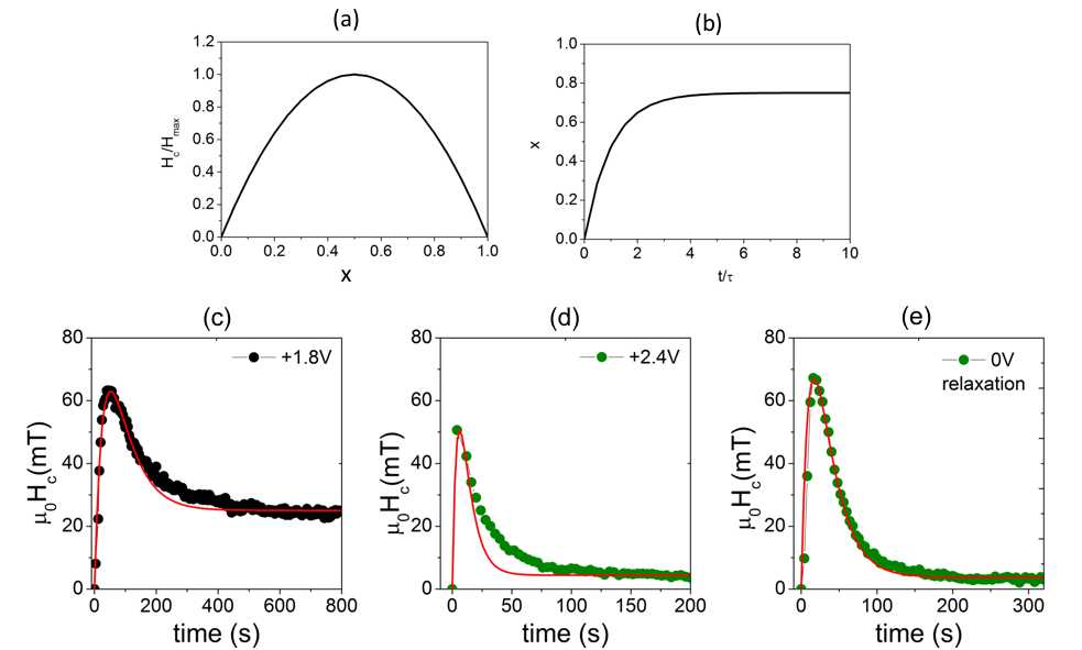
Previous studies carried out for several Pt/Co/oxide stacks [2, 4, 5, 6, 7] show that the PMA changes with the cobalt oxidation following a typical bell-like curve, with a maximum corresponding to the optimum oxidation state. This curve may be approximated by a parabola, as sketched in Figure 5(a), where the oxidation rate is represented by the parameter : here =0 corresponds to the IP-OOP transition; =1/2 corresponds to optimum oxidation and maximum PMA; =1, corresponds to the OOP-IP transition. We assume that the model is valid both for the oxidation and the reduction mechanism. We also assume that the coercive field is proportional to the anisotropy Keff [23] and that this has a quadratic dependence on i.e. that Keff(x) = 4 K. We then have (Figure 5(a)):
| (1) |
The applied electric field modifies the oxidation of the cobalt layer and we assume that the oxidation rate follows an exponential law with a characteristic time (Figure 5(b)). The system is always prepared (reset) with =0 at =0 (IP-OOP transition). The oxidation state observed at time depends on the strength of the electric field and will be called .
| (2) |
By putting H and together we obtain:
| (3) |
where the maximum of is obtained for .
In Figures 5(c-d) the experimental variations of the coercivity versus time obtained for bias voltage Vg=+1.8 V and +2.4 V (Figure 3(a)) are fitted with the expression in Equation 3, using and as fitting parameters. The proposed model appears to describe well the experimental curve obtained with the lower bias voltage (Vg=+1.8 V), except for a small deviation observed for coercive fields smaller than 40 mT in the under-oxidized part of the curve. For Vg=+2.4 V the model fails to describe the part of the curve with 0 Hc 40 mT in the under-oxidized part of the curve, where the decay of the coercivity is much lower than that described by Equation 3. Following the discussion of the previous section, this behaviour might be explained by the spontaneous re-oxidation of the cobalt layer occurring, for , through the diffusion of oxygen towards the Co interface, therefore counteracting the effect of the positive bias voltage.
Interestingly, Figure 5(e) shows that the experimental coercivity versus time curve describing the re-oxidation of the Co interface after removal of the bias voltage (as in Figure 4(c)) can be perfectly fitted with the oxidation rate law described by our model. This results is in agreement with the theory developed in 1949 by Cabrera and Mott who proposed that the growth of very thin oxide layers at room temperature occurs following an exponential law, similarly to Equation 2 [17]. As far as we know, the ”real time” variation of PMA of a magnetic stack occurring during the oxidation of a metallic layer has not been observed before.
7 Exponential decrease of the switching time between IP and saturated OOP states
The voltage-driven oxidation/reduction kinetics was also studied for a Pt/Co(0.6)/AlOx sample. In this case the measurements were carried out on a 2x2 capacitor-like structure. In the initial state (time =0) the Co layer is over-oxidized with vanishing coercivity and IP magnetization.
The curves in Figure 6(a) show the variation of the coercive field as a function of time, during the application of several positive bias voltages driving oxygen ions away from the Co/oxide interface. Similarly to Pt/Co/TbOx, for every bias voltage the coercivity, and therefore the interfacial PMA, increases rapidly up to the maximum, then decreases slowly in the part of the curve where Co is under-oxidized.
The duration of the gate voltage pulse needed to switch the magnetization between the initial over-oxidized state with IP magnetization and the state with maximum PMA state and viceversa (Figure 6(b-c)) were measured, for positive and negative bias respectively (Figure 6(d)). The switching times are observed to change by 5 orders of magnitude in the used voltage range, e.g. in the oxidation process, the switching time varies between 420 s for -0.5V to 10 ms for -6.5 V. In both the oxidizing and the reducing process and over the whole time range, the switching time decreases exponentially with the bias voltage. Moreover, with an equivalent (and opposite) bias voltage, the oxidation process is faster than the reduction.
8 Discussion
Let’s summarise the main results of this work:
I) the switching time between an over-oxidized state with in-plane anisotropy (corresponding to the formation of an Co oxide layer of a certain thickness ) and the state with OOP magnetization with maximum PMA (which we associate to a state with Co covered with one monolayer of oxygen atoms) decreases exponentially with the applied gate voltage.
II) the time dependence of the PMA (i.e. of the oxidation/reduction of the Co layer) can be well described by Equation 2, that supposes an exponential decrease of the oxidation/reduction rate as a function of time. This is the case both for the bias-driven oxidation/reduction and for the spontaneous re-oxidation of the under-oxidized Co layer in Pt/Co(1.1)/TbOx, once the bias is removed.
Both the exponential variation of the switching time and the exponential time-dependence of the oxidation rate of the cobalt layer can be explained by the atomistic model developed by Cabrera and Mott in the 1940’s [17] to explain the growth rate of very thin oxide films. According to the authors, the rate of oxidation is limited by the injection of defects (i.e. the migration of ionic species) within the oxide layer and across the metal/ion interface. These ionic species are driven by the electric field present at the interface between a metal and the thin oxide, due to the contact potential difference between the metal and the adsorbed oxygen ion layer. According to the authors, for thin oxide layers of thickness , the electric field , can be so strong that the drift velocity of the ions is no longer linear with , but changes exponentially with it.
From Refs. [17, 24], for strong electric fields (), the ion drift velocity reads:
| (4) |
where is the characteristic field for the ion (typically 1 MV/cm for T = 300 K), is the electrical charge of the ion, is the attempt frequency for the ion jumps (typically 1012-1013 Hz), is the periodicity of the ion vacancy sites in the material and is the activation energy of the ion jump from one site to the next.
From Equation 4 follows that the rate of growth of the oxide film decreases exponentially with the film thickness, as the electric field is proportional to 1/.
These arguments may be applied to our system. Let us first consider the results shown in Figure 6. If we assume that the switching time is mainly limited by the drift velocity of the oxygen ions across the ZrO2 layer (=10 nm), so that , the exponential variation of obtained with fields of the order of 1 MV/cm is in agreement with the theorical model just described. From the slope of the experimental velocity curves for negative and positive bias (oxidation and reduction processes, Figure 6), we obtain 0.6 x 10⁶ V/cm, which is in the range expected for the non-linear ionic transport. The best fit of the two curves to Equation 4 gives 1 eV, with a small difference between the activation energies for negative and positive bias, 3.3 , that can also be obtained from the shift of the two curves.
A question arises on whether the rate-limiting barrier is situated in the dielectric layer or at the metal/oxide interface. The small difference (with respect to the enthalpy of formation of Co oxide) between the barriers for positive and negative bias voltages, leads us to propose that the switching time is limited by the barrier associated to ionic migration in ZrO2. The value of 1 eV obtained in this work is of the same order of magnitude of that recently calculated for oxygen ion migration via oxygen vacancies in monoclinic ZrO2 [25]. The lower activation barrier, compared to experimental values found in the literature ( 2 eV) may be associated to the amorphous sub-stoichiometric nature of our oxide, which was grown by ALD at low temperature to avoid deteriorating the magnetic properties of the magnetic stacks.
The curve describing the natural re-oxidation of the Co layer after the removal of the bias voltage (Figs. 4 and 5(e), that we fitted assuming an exponential decrease of the oxidation rate as a function of time, is also in agreement with the model developed by Cabrera and Mott, that predicts an exponential variation of the growth rate of the oxide as a function of its thickness. It is interesting to note that the characteristic time for the re-oxidation of the Co layer (with Vg=0) is comparable to that obtained for the Co oxidation under a bias voltage Vg=+1.5V (E=1.5 MV/cm). This seems to prove that the electric field at the metal/oxide interface is indeed extremely large, of the order of some 1 MV/cm.
9 Conclusion
We have shown that a ZrO2 layer deposited on top of Pt/Co/MOx microstructures acts as a ionic conductor that, under the action of a gate voltage, draws oxygen ions towards/away from the Co layer, modifying its oxidation and therefore the anisotropy of the magnetic stacks. The effect on the magnetic properties is large and reversible. The temporal stability of the effect depends on the oxidation state of the Co layer after the application of the gate voltage i.e. we have observed that strongly under-oxidized Co layers in Pt/Co(1.1)/TbOx stacks spontaneously re-oxidize. The temporal variation of the anisotropy during the application of the gate voltage has been explained supposing a parabolic variation of the PMA and an exponential decrease of the oxidation/reduction as a function of time. We have shown that the voltage-driven switching time between different magnetic configurations decreases exponentially with the applied voltage, and can be decreased by several orders of magnitude, down to a few ms, by tuning the amplitude of the electric field between 1 and 6 MV/cm. The microscopic mechanism can be explained by a theoretical model predicting the exponential variation of the ion drift velocity for very large electric fields. The possibility to explain the observed effect with a relatively simple theoretical model opens the possibility to engineers materials with optimized properties.
10 Acknowledgements
We acknowledge the support of the Agence Nationale de la Recherche (projects ANR-17-CE24-0025 (TOPSKY), ANR-16-CE24-0018 (ELECSPIN) and ANR-19-CE24-0019 ADMIS)) and of the DARPA TEE program through Grant No. MIPR HR0011831554. The authors acknowledge funding from the European Union’s Horizon 2020 research and innovation program under Marie Sklodowska-Curie Grant Agreement No. 754303 and No. 860060 “Magnetism and the effect of Electric Field” (MagnEFi). J.P.G. also thanks the Laboratoire d'Excellence LANEF in Grenoble (ANR-10-LABX-0051) for its support. B. Fernandez, T. Crozes, Ph. David, E. Mossang and E. Wagner are acknowledged for their technical help. A.F. thanks O. Fruchart for his support for the MFM experiments. S.P. thanks M. Maroun and Ph. Allongue for the many inspiring discussions.
References
- [1] M. Nichterwitz, S. Honnali, M. Katuzau, J. Zehner, K. Nielsch, and K. Leistner. Advances in magneto-ionic materials and perspectives for their application. APL Mater., 9:030903, 2021.
- [2] S. Monso, B. Rodmacq, S. Auffret, G. Casali, F. Fettar, B. Gilles, B. Dieny, and P. Boyer. Crossover from in-plane to perpendicular anisotropy in Pt/CoFe/AlOx sandwiches as a function of Al oxidation: A very accurate control of the oxidation of tunnel barriers. Appl. Phys. Lett., 80:4157, 2002.
- [3] H. X. Yang, M. Chshiev, B. Dieny, J. H. Lee, A. Manchon, and K. H. Shin. First-principles investigation of the very large perpendicular magnetic anisotropy at Fe/MgO and Co/MgO interfaces. Phys. Rev. B, 84:054401, 2011.
- [4] A. Manchon, C. Ducruet, L. Lombard, S. Auffret, B. Rodmacq, B. Dieny, S. Pizzini, J. Vogel, V. Uhlír̆, M. Hochstrasser, and G. Panaccione. Analysis of oxygen induced anisotropy crossover in Pt/Co/MOx trilayers. J. Appl. Phys., 104:043914, 2008.
- [5] A. Manchon, S. Pizzini, , J. Vogel, V. Uhlír̆, L. Lombard, C. Ducruet, S. Auffret, B. Rodmacq, B. Dieny, M. Hochstrasser, and G. Panaccione. X-ray analysis of oxygen-induced perpendicular magnetic anisotropy in Pt/Co/AlOx trilayers. J. Magn. Magn. Mater., 320:1889, 2008.
- [6] A. Manchon, S. Pizzini, V. Vogel, J. Uhlír̆, L. Lombard, C. Ducruet, S. Auffret, B. Rodmacq, B. Dieny, M. Hochstrasser, and G. Panaccione. X-ray analysis of the magnetic influence of oxygen in Pt/Co/AlOx trilayers. J. Appl. Phys., 103:07A912, 2008.
- [7] B. Dieny and M. Chshiev. Perpendicular magnetic anisotropy at transition metal/oxide interfaces and applications. Rev. Mod. Phys., 89:025008, 2017.
- [8] M. Weisheit, S. Fähler, A. Marty, Y. Souche, C. Poinsignon, and D. Givord. Electric field-induced modification of magnetism in thin-film ferromagnets. Science, 315:349, 2007.
- [9] T. Maruyama, Y. Shiota, T. Nozaki, K. Ohta, N. Toda, M. Mizuguchi, A. A. Tulapurkar, T. Shinjo, M. Shiraishi, and S. Mizukami. Large voltage-induced magnetic anisotropy change in a few atomic layers of iron. Nat. Nanotech., 4:158, 2009.
- [10] F. Matsukura, Y. Tokura, and H. Ohno. Control of magnetism by electric fields. Nat. Nanotech., 10:209, 2015.
- [11] C. Bi, Y. Liu, T. Newhouse-Illige, M. Xu, M. Rosales, J. W. Freeland, O. Mryasov, S. Zhang, S. G. E. Velthuis, and W. G. Wang. Reversible control of Co magnetism by voltage induced oxidation. Phys. Rev. Lett., 113:267202, 2014.
- [12] U. Bauer, Y. Lide, J. T. Aik, P. Agrawal, S. Emori, H.L. Tuller, S. van Dijken, and G.S.D. Beach. Magneto-ionic control of interfacial magnetism. Nat. Mater., 14:174, 2015.
- [13] X. Zhou, Y. Yan, M. Jiang, B. Cui, F. Pan, and C. Song. Role of oxygen ion migration in the electrical control of magnetism in Pt/Co/Ni/HfO2 films. The Journal of Physical Chemistry C, 120:1633, 2016.
- [14] A.J. Tan, M. Huang, S. Sheffels, F. Büttner, S. Kim, A.H. Hunt, I. Waluyo, H.L. Tuller, and G. S. D. Beach. Hydration of gadolinium oxide (GdOx) and its effect on voltage-induced Co oxidation in a Pt/Co/GdOx/Au heterostructure. Phys. Rev. Materials, 3:064408, 2019.
- [15] A.J. Tan, M. Huang, C.O. Avci, F. Büttner, M. Mann, W. Hu, C. Mazzoli, S. Wilkins, H.L. Tuller, and G. S. D. Beach. Magneto-ionic control of magnetism using a solid-state proton pump. Nat. Mater., 18:35, 2019.
- [16] Ki-Young Lee, Sujin Jo, Aik Jun Tan, Mantao Huang, Dongwon Choi, Jung Hoon Park, Ho-Il Ji, Ji-Won Son, Joonyeon Chang, Geoffrey S. D. Beach, and Seonghoon Woo. Fast magneto-ionic switching of interface anisotropy using yttria-stabilized zirconia gate oxide. Nano Letters, 20:3435, 2020. PMID: 32343588.
- [17] N. Cabrera and N.F. Mott. Theory of the oxidation of metals. Rep. Prog. Phys., 12:163, 1949.
- [18] Aymen Fassatoui, Jose Peña Garcia, Laurent Ranno, Jan Vogel, Anne Bernand-Mantel, Hélène Béa, Sergio Pizzini, and Stefania Pizzini. Reversible and irreversible voltage manipulation of interfacial magnetic anisotropy in //oxide multilayers. Phys. Rev. Applied, 14:064041, 2020.
- [19] A. Hubert and R. Schäfer. Magnetic Domains, The Analysis of Magnetic Microstructures. Springer: Berlin, 1998.
- [20] B. Kaplan and G. A. Gehring. The domain structure in ultrathin magnetic films. J. Magn. Magn. Mater., 128:111, 1993.
- [21] O. Boulle, J. Vogel, H. Yang, S. Pizzini, D. de Souza Chaves, A. Locatelli, T.O. Mentes, A. Sala, L. D. Buda-Prejbeanu, O. Klein, M. Belmeguenai, Y. Roussigné, Y., A. Stashkevich, S.M. Chérif, L. Aballe, M. Foerster, M. Chshiev, S. Auffret, I.M. Miron, and G. Gaudin. Room-temperature chiral magnetic skyrmions in ultrathin magnetic nanostructures. Nat. Nanotech., 11:449, 2016.
- [22] R. Juge, S.-G. Je, D. de Souza Chaves, L. Buda-Prejbeanu, J. Peña Garcia, J. Nath, I.M. Miron, K.G. Rana, L. Aballe, M. Foerster, F. Genuzio, F.O. Mentes, A. Locatelli, F. Maccherozzi, S.S Dhesi, M. Belmeguenai, Y. Roussigné, S. Pizzini, G. Gaudin, J. Vogel, and O. Boulle. Current-Driven Skyrmion Dynamics and Drive-Dependent Skyrmion Hall Effect in an Ultrathin Film. Phys. Rev. Applied, 12:044007, 2019.
- [23] Dominique Givord, Michel Rossignol, and Vitoria M.T.S. Barthem. The physics of coercivity. Journal of Magnetism and Magnetic Materials, 258-259:1–5, 2003. Second Moscow International Symposium on Magnetism.
- [24] D.B. Strukov and R.S. Williams. Exponential ionic drift: fast switching and low volatility of thin-film memristors. Appl. Phys A, 94:515, 2009.
- [25] J.H. Hur. First principles study of oxygen vacancy activation energy barrier in zirconia-based resistive memory. Sci. Rep., 10:5405, 2020.