Ultra-low Threshold Titanium doped sapphire Whispering-gallery Laser
Abstract
Titanium doped sapphire (Ti:sapphire) is a laser gain material with broad gain bandwidth benefiting from the material stability of sapphire. These favorable characteristics of Ti:sapphire have given rise to femtosecond lasers and optical frequency combs. Shaping a single Ti:sapphire crystal into a millimeter sized high quality whispering gallery mode resonator () reduces the lasing threshold to and increases the laser slope efficiency to 34%. The observed lasing can be both multi-mode and single-mode. This is the first demonstration of a Ti:sapphire whispering gallery laser. Furthermore, a novel method of evaluating the gain in Ti:sapphire in the near infrared region is demonstrated by introducing a probe laser with a central wavelength of . This method results in decreasing linewidth of the modes excited with the probe laser, consequently increasing their . These findings open avenues for the usage of whispering gallery mode resonators as cavities for the implementation of compact Ti:sapphire lasers. Moreover, Ti:sapphire can also be utilized as an amplifier inside its gain bandwidth by implementing a pump-probe configuration.
I Introduction
Titanium doped sapphire (Ti:sapphire) has been the workhorse behind solid state lasers since its invention in 1986 [1]. Its broad gain bandwidth – ranging from up to – and peak absorption wavelengths between and [2] made it the gain material of choice for solid state lasers [3], ultra-short pulse lasers [4], wide wavelength range tunable lasers, and femtosecond lasers [5, 6]. Adding on top sapphire’s excellent thermal conductivity and material strength, Ti:sapphire oscillators are used to generate femtosecond pulses with megahertz repetition rates [7, 8] and high-power chirped pulse amplification [9], generating output powers as high as [10]. Moreover, Ti:sapphire lasers have also been used to demonstrate frequency combs [11] and to study ultrafast dynamics of atomic, molecular, and condensed matter [12, 13, 14].
Here we present a new take on the material that will allow us to surpass the current records in lasing threshold and slope efficiency by fabricating an ultra-high quality whispering gallery mode resonator out of Ti:Sapphire. The lasing threshold is directly reliant on the quality factor (-factor) of the resonator and the volume () of the mode inside the cavity. The -factor gives a measure of the optical loss inside the cavity, whereas affects the field strength inside the cavity [15] via the Purcell effect. A high -factor and a low , give rise to stronger coupling between gain medium and the field of the cavity [16, 17, 18]. This in turn translates into a possible low lasing threshold and narrow linewidths [19, 20]. In lasers the gain compensates the losses, therefore slight improvements in the -factor of the resonator have been observed [21, 22, 23]. These can lead to an increase in the sensitivity of resonator-based optical sensors [21, 24].
Dielectric whispering gallery mode resonators (WGMRs) confine the light via total internal reflection at their rotationally symmetric boundary [25]. They are particularly well suited for lasing feedback as the gain material itself acts as the cavity. When these active WGMRs are used together with a suitable pump source, lasing is observed [26]. A WGMR laser is usually referred to as whispering gallery laser (WGL). WGLs have been demonstrated with resonators made of gain material of different shapes such as toroids [27, 28], rings [29, 30, 31], microspheres [32, 33, 34], asymmetric resonators [35, 36, 37, 38] and disks [39, 40].
As opposed to fabricating a WGMR from an active material to achieve lasing, a passive WGMR can be coated with an active material. A continuous-wave (CW) laser has been demonstrated by coating a polystyrene microsphere by -doped energy-looping nanoparticles [41]. Moreover, instead of pumping WGMRs by light, they can be pumped electrically. A semiconductor microdisc laser has been demonstrated by applying InGaAs quantum well-dots as the active area via dry-etching and photo-lithography [42]. Finally, there is a separate class of WGLs that use a passive WGMR just as a filter cavity [43, 44, 45, 46, 47].
In this work we demonstrate a disc-shaped Ti:sapphire WGL. Previously, there have been some studies on frequency stability of cryogenic Ti:sapphire WGMRs in the microwave domain [48, 49, 50], but, to the best of our knowledge, no study has been performed on lasing in the optical domain. Our WGMR has exhibited the highest recorded critical -factors at and , and respectively, for Ti:sapphire. As a laser pumped at it has an input-power threshold of and a slope efficiency of in multi-mode operation, based on the pump power coupled into the resonator at the onset of lasing. This is the lowest observed Ti:sapphire lasing threshold to the best of our knowledge.
II Experiments
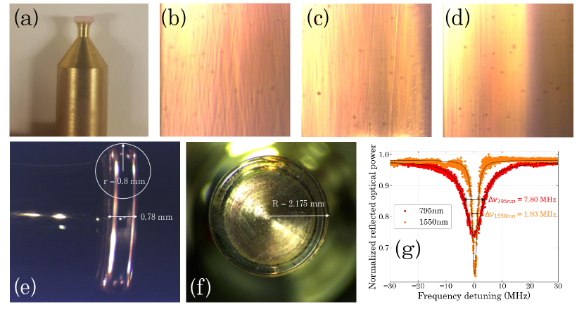
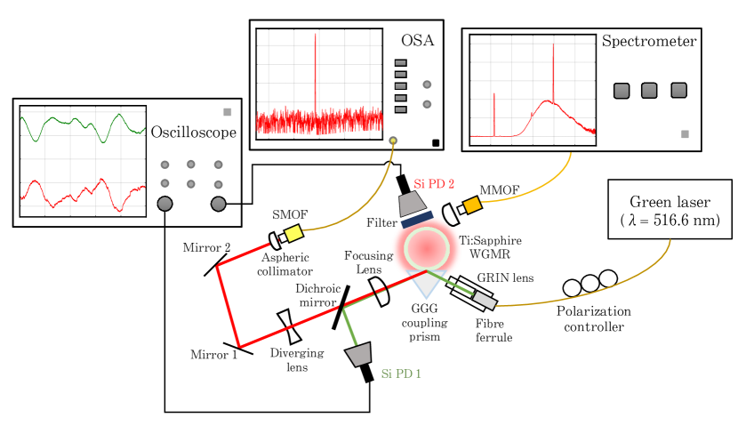
We fabricated a single crystalline Ti:sapphire WGMR as shown in Figure 1(a-f) (see Methods section IV.1). Light was coupled into the resonator evanescently through prism coupling [25] (see Figure 2 and Methods section IV.2). First we determined the -factor around and by scanning two different tunable diode lasers over a resonance while changing the coupling distance of the prism (see Supplement), measuring a critical -factor of and , respectively (see Figure 1(g)). The lower -factor at is expected due to the re-absorption of titanium in the WGMR, and not due to the surface quality. Both -factors are slightly lower than reported in the study performed by [51] on undoped sapphire. In order to observe lasing, we coupled a tunable green laser () evanescently into the WGMR. The resonator fluorescence was detected by imaging a segment of the resonator’s rim into a spectrometer, while the near-infrared (IR) output was observed through the coupling prism using an optical spectrum analyzer (OSA). The rim fluorescence was also detected by a photodiode. The -factor in the green is of the order of (see Supplement), as expected for the strong absorption of the titanium dopant.
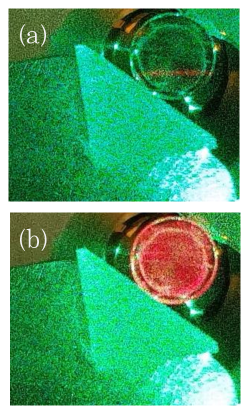
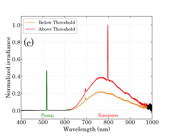
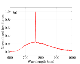
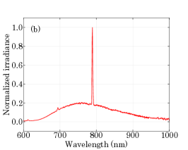
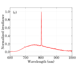
Lasing in the WGMR can be either multi-mode or single-mode. Different lasing modes can be excited by changing parameters in the experimental setup such as the pump coupling angle, its polarization, coupling strength controlled by the distance between the prism and the resonator, and the input power of the pump laser. By varying these parameters we can excite different pump WGMs in the resonator which gives rise to different lasing modes. Once the pump laser is coupled into the resonator at a high enough efficiency, fluorescence is excited in the WGMR. The fluorescence inside the resonator can be observed with the naked eye and photographed, as shown in Figure 3. Figure 3(a) shows the WGMR when there is a significant distance between the prism and the resonator, i.e., the green light is not coupled into the WGMR. Figure 3(b) shows the resonator when the green light is coupled to the resonator. The fluorescence inside the resonator can be observed as a bright reddish glow. The first observation of lasing is shown in Figure 3(c), which shows the pump and the emission spectra of the imaged resonator; the orange line shows the emission data collected by the spectrometer when the lasing threshold is not exceeded, whereas the red line shows the same when the lasing threshold is exceeded. A lasing peak is clearly seen near . The small peak observed at is due to traces of chromium (ruby) doping [52].
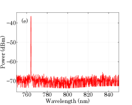
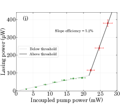
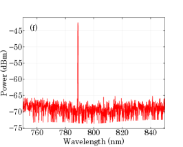
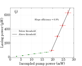
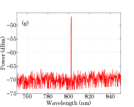
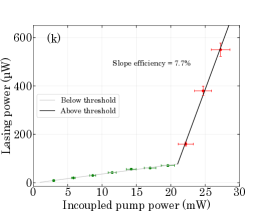
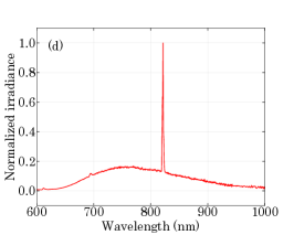
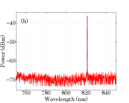
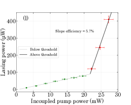
We reach the single-mode regime by adjusting the pump mode so that it favours one lasing mode. This process is know to be highly selective [53, 54, 55], depending on the actual spatial profile of the pump mode. Various single-mode lasing peaks were observed during the experiment. Figures 4(a), (b), (c) and (d) show the spectrometer data for different lasing modes, whereas Figures 4(e), (f), (g) and (h) show the OSA data for the same modes. Figures 4(i), (j), (k) and (l) show the lasing threshold for these lasing modes observed at the central wavelengths of , , , and , respectively, by varying the green pump power from zero to the full power achievable. The theoretical model predicts two different linear slopes below and above the threshold [56]. We obtain the above-threshold slope efficiencies for these different lasing modes of 5.2%, 6.9%, 7.7% and 5.7%, respectively. The exact lasing thresholds are also different for the shown modes. The slope efficiencies and thresholds are expected to be different for different modes due to the intricate interplay between gain profile, pump mode, pump power, coupling efficiency, and gain competition. As the OSA resolution is limited to at the lasing wavelengths, we have confirmed single mode lasing by observing no beat signal of the lasing mode on a fast photo detector (bandwidth ), which is larger than one free spectral range.
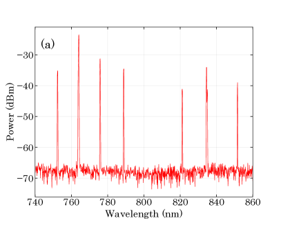
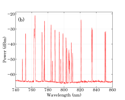
Multi-mode lasing in our WGL is typically triggered when different lasing modes do not compete with each other. Figure 5(a) shows the multi-mode lasing peaks observed in a single OSA sweep. At least seven different lasing peaks are observable in the plot at wavelengths of , , , , , , and , spanning a range of almost . Figure 5(b) shows all of the multi-mode lasing peaks recorded using the max hold function of the OSA. These peaks were recorded while parameters such as the pump power, polarization, and coupling conditions were changed. The shortest wavelength lasing peak recorded in the figure is at , whereas the longest wavelength lasing peak is at . This confirms that the Ti:sapphire WGL has a range spanning more than .
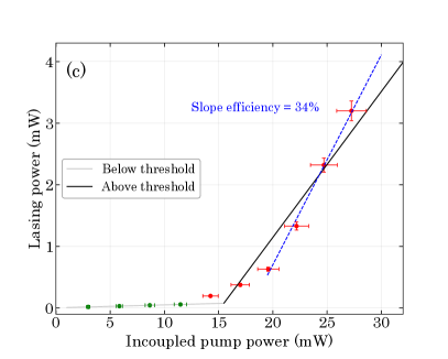
The cumulative lasing power versus the input pump power for multi-mode lasing is plotted in Figure 5(c). For this the power of the green pump laser is varied from zero to the full power achievable. At the optimal coupling conditions, i.e., coupling angles and coupling rates, the onset of lasing occurs at . We attribute this to the excitation of the first lasing WGM which has the lowest threshold. As the pump power increases, more WGMs with higher thresholds begin to lase, which leads to a nonlinear character of the slope efficiency in Figure 5(c) in the intermediate power regime. Finally, at around , no new modes are excited and we observe a clear linear behavior with the multi-mode slope efficiency corresponding to 34%. Considering that the single mode lasing has a slope efficiency of around 5% (see above), the simultaneous lasing of seven modes is consistent with the observed multi-mode slope efficiency.
II.1 Comparison with other Ti:sapphire lasers
One of the very first demonstrations of a low threshold Ti:sapphire laser was made in 1986 [57], with a threshold of and a slope efficiency of 5% recorded for a mode having a central wavelength of , whereas the laser was tunable around a range between to .
To classify different Ti:sapphire crystals a figure of merit (FOM) can be defined as the ratio of absorption coefficients for the pump and the emission wavelength, FOM = / [58, 59, 60, 61, 62, 63]. Slope efficiencies as high as 42% and 34% were demonstrated for high threshold values of and respectively for Ti:sapphire crystals with different FOMs [61]. In these experiments the lasing wavelengths range from to with pump at .
Furthermore, a low threshold of with a slope efficiency of 6% was demonstrated [64] for a mode at and with the laser having a tuning range of to . Other low threshold values reported for Ti:sapphire lasers exist in the range of to [65, 66, 67, 68, 69, 70].
Moreover, the main cavity of choice for Ti:sapphire lasers has been the mirror cavity, with some studies being performed on waveguides and a fibre laser. The most commonly used pump wavelength is . All of these values are reported in Table 1 and are compared to our results. Previously, the lowest recorded threshold values for single-mode lasing was [69] with a slope efficiency of 8.9% in waveguide based Ti:sapphire laser operating at . The highest slope efficiency of 42% was reported for a relatively higher threshold value of [61] for a mode at . However, in this case the Ti:sapphire crystal was pumped with multi-mode argon-ion laser source covering a range of to . Whereas the highest slope efficiency for a Ti:sapphire laser pumped with a single wavelength of [66] is 30% for a threshold of . In our experiments we have demonstrated high slope efficiencies for both single-mode and multi-mode operation and the lowest recorded thresholds in both regimes.
| Threshold | Slope | Cavity | Emission / | () | Emission | Year | Reference |
|---|---|---|---|---|---|---|---|
| () | efficiency | type | Range () | Regime | |||
| 14.2 | 34% | WGMR | 744.4 - 873.5 | 516.6 | Multi-mode | 2021 | This work |
| 19.5 | 7.7% | WGMR | 788.8 | 516.6 | Single-mode | 2021 | This work |
| 55111Found in supplementary information | 8.9% | Waveguide | 798.5 | 532 | - | 2018 | [69] |
| 60 | 15% | Mirror | 800 | 532 | Multi-mode | 2011 | [66, 71] |
| 84 | 4.5% | Waveguide | 798.25 | 532 | - | 2012 | [68] |
| 90 | 6% | Mirror | 800 | 514.5 | - | 1991 | [64] |
| 106 | 16% | Mirror | 795 | 532 | Multi-mode | 2009 | [70, 71] |
| 116 | 30% | Mirror | 800 | 532 | Multi-mode | 2011 | [66, 71] |
| 118.2 | 29.6% | Fibre Laser | 769 - 832 | 532/520 | Multi-mode | 2016 | [67] |
| 120 | - | Mirror | 840 | 532 | - | 2002 | [65] |
| 220 | 12% | Mirror | 800 | 488 - 515 | - | 1994 | [61] |
| 300 | 5% | Mirror | 720 | 488 | - | 1986 | [57] |
| 400222Approximated from Figure 3 | 23.5% | Waveguide | 798.25 | 532 | - | 2012 | [68] |
| 572 | 5% | Mirror | 783 | 452 | Multi-mode | 2009 | [70, 71] |
| 600 | 34% | Mirror | 800 | 488 - 515 | - | 1994 | [61] |
| 750 | 42% | Mirror | 800 | 488 - 515 | - | 1994 | [61] |
II.2 Amplification in Ti:sapphire WGL
Once the lasing was observed in the Ti:sapphire WGL, the setup was modified, so that we can observe the amplification of a laser probe coupled to the WGM within the gain region, see Figure 6. A probe laser with a central wavelength of is coupled in to the resonator using a diamond prism, while the green laser remains coupled through the GGG prism. The resonator rim fluorescence is still collected into the spectrometer, and the excited WGMs are observed with the oscilloscope. For the passive resonator the overall linewidth of a WGM is given by:
| (1) |
where is the intrinsic linewidth due to the material absorption and surface scattering, represents the coupling linewidth of the diamond prism, and shows an additional coupling linewidth due to the GGG prism used to couple the green pump laser. For an active resonator where the green pump laser is turned on and the WGMs excited at , the gain results in a decrease in the total linewidth:
| (2) |
where is the linewidth of the same system but with the gain () introduced in the WGMR, courtesy of the green pump.
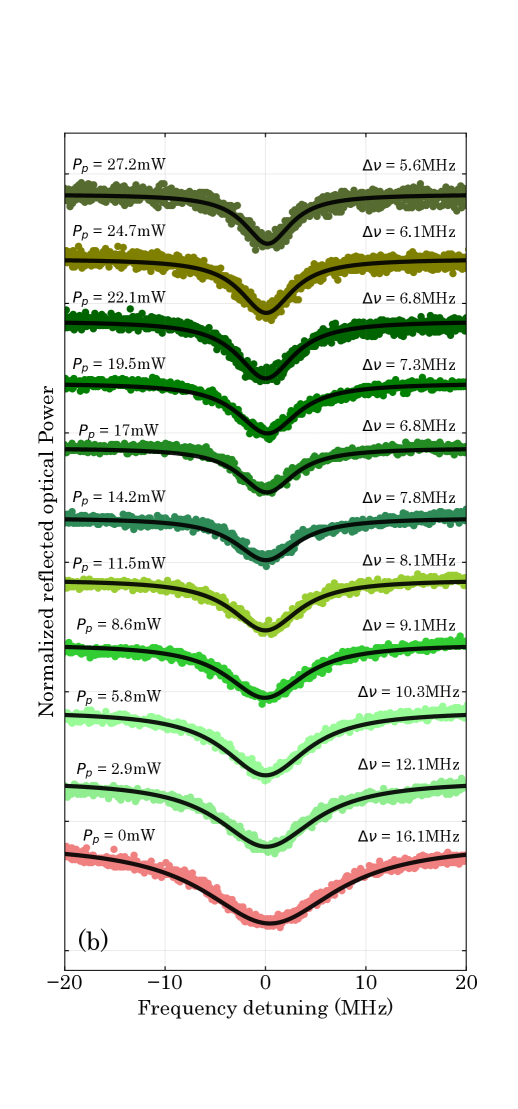
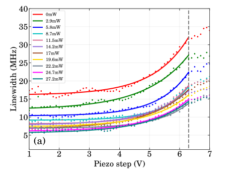
In order to show the linewidth narrowing expressed by equation (2), we first choose a WGM which is excited by the probe laser at approximately . Then the distance between the GGG (pump) prism and the WGMR is fixed such that it provides the maximum gain, which is confirmed by observing lasing with the spectrometer. Next we record the linewidth values of a high -factor mode while moving the diamond prism using the piezo positioner (see figure S7 in section 6 of the supplemental document), from far away (undercoupled regime) to all the way to touching the resonator (maximally overcoupled regime), at various powers of the green pump, see Figure 7(a). The dashed grey vertical line in the figure at shows the position where the diamond prism is touching the resonator. In each case, an exponential has been fitted to the data before the resonator and prism touch. The asymptote of this exponential linewidth dependence gives the linewidth in the limit that there is no coupling to the diamond prism, i.e., . Here the measured gain is the so called small-signal gain, where any saturation effects are ignored, as we are in the limit that no light of is coupled into the resonator. These asymptotic linewidth values for a fixed distance (voltage) are plotted in Figure 7(b).
 |
|
|---|---|
 |
|
 |
|
 |
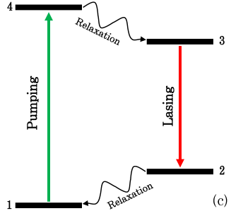
The theoretical fit to the linewidth vs. pump power is found from the expression for the gain in a four-level laser systems with titanium number density and population number densities , see Figure 7(c) [72]
| (3) |
where is a parameter describing the transverse overlap between the pumping and lasing WGMs, the refractive index of the lasing mode, and is the emission cross section. For perfectly overlapping modes , but in realistic scenarios . In our proof-of-principle experimental setup we do not have a control over , and will consider it as a free parameter. The population inversion of a four-level laser system is given by [72]
| (4) |
where is the life time of the excited state of the lasing transition, and the pumping (emission) rates () are related to the intracavity intensities () as
| (5) |
with the pump (emission) frequency (), the absorption cross section of the pump , and the emission cross section .
The intracavity pump intensity can be estimated as
| (6) |
where is the pump mode volume, hence is its cross section, where is the resonator’s radius. The mode volume is estimated in Section 2.1 of the supplemental document. The factor is the intracavity power enhancement of the pump assuming that the mode is approximately critically coupled, where
| (7) |
is the pump mode finesse, with the pump wavelength , the pump quality factor , and the refractive index at the pump frequency .
Typically can be ignored in Equation (4). The mode that we measured, however, did not lase at high pump power. We therefore know that there were competing modes with better pump overlaps so is not necessarily negligible in our experiment, as the light emitted into other modes that overlap with our chosen mode contributes to it. We can estimate by reasoning that the photons at the fluorescence wavelength have been created by emission after a pump photon has been absorbed. It is well observed that the spontaneous emission of a laser below threshold grows proportional to its pump power. The intensity of fluorescence is then
| (8) |
where is the fraction of pump photons that undergo spontaneous emission below threshold. The other factors account for the energy difference of the photons and the different intracavity field enhancement.
Now we have the fitting function of a form
| (9) |
where
| (10) |
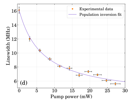
This fit is shown as the solid line in Figure 7(d). It is in excellent agreement with the data. The error bars originate from the Lorentzian fit on -axis and the power meter on the -axis. From the fitted values of and we can estimate that
| (11) |
From the magnitude of , we see that intracavity spontaneous emission is indeed significant during this experiment. The value of roughly gives the magnitude of the gain improvement that is theoretically possible by facilitating a better overlap of the modes e.g., by optimizing the rim shape, or simply by choosing a better overlapping pair of the pump and amplified modes available in the present resonator geometry.
III Conclusion
In conclusion, we have for the first time demonstrated a Ti:sapphire WGL. The WGL operates in both single-mode and multi-mode regimes, with a range spanning over and a high slope efficiency of 34%. The threshold value of reported, is the lowest reported for a Ti:sapphire laser to the best of our knowledge. Moreover, we demonstrated a novel method of using the gain in the resonator to enhance the -factor of WGMs at , due to the gain inside the resonator acting as a negative loss mechanism for a wavelength within the excitation range of Ti:sapphire. The trend shown by the linewidth values of the WGM with the increase of the pump power was explained using the population inversion model of a four-level laser system.
There are a number of opportunities for further investigations of this unique solid-state laser platform. By reducing the mode volume in the resonator the threshold should drop even further. Selectively pumping the region of the rim of the resonator through Bessel beams [73] would reduce the losses induced by the green coupling prism [74, 75] at the cost of losing the resonant enhancement of the green mode (finesse ). This will also provide more control over the pump light overlap with the lasing modes, and make the pump intensity independent from the lasing modes coupling rate. The pump laser used in this study could only achieve a highest absorbed pump power of ; at higher pump powers the range of this Ti:sapphire WGL will increase. Exploring Ti:sapphire crystals of different FOM to fabricate the WGMR can also result in better threshold and slope efficiencies. As it has been shown experimentally before that different FOM crystals can result in better outputs, i.e., lower thresholds, higher slope efficiencies and higher output powers [61, 70]. Finally, the experimental results reported in this work are very promising for the implementation of a more compact and efficient Ti:sapphire laser.
IV Experimental methods
IV.1 WGMR fabrication and testing
At the core of this study is the Ti:sapphire WGMR. First, a piece was cut from a Ti:sapphire crystal (titanium density , see Section 1 of the supplemental document) with a diamond saw. The crystal was cut in the -cut configuration, i.e., the optic axis of the crystal coincides with the symmetry axis of the resonator. Afterwards, the -cut piece was glued to a brass rod using mounting wax, as shown in Figure 1(a). Next the curvature of the resonator surface was shaped using a dental drill, while the brass rod was rotating via a turning machine. The curved disc was then polished using basic diamond slurry solutions of with progressively smaller particle sizes. The particle size was chosen depending on the coarseness of the surface of the resonator. First the resonator was polished using polycrystalline diamond slurry with average particle size; the quality of the resonator surface after this round of polishing is shown in Figure 1(b). The resonator was further polished with slurries. The results after polishing with are shown in Figure 1(c) and (d). At each stage of polishing the surface roughness is improved. After each step of polishing the resonator is cleaned thoroughly to avoid cross-contamination of diamond particles.
The final resonator can be seen in Figure 1(e) and (f). The side-view of the finalized Ti:sapphire WGMR, captured using a microscope can be seen in Figure 1(e). The resonator has a thickness of and a radius of curvature of . The top-view of the resonator showing it’s radius, can be see in Figure 1(f). The -factor of the resonator was tested throughout the polishing process. The best recorded values for the critically coupled linewidths at and are and respectively, as shown in Figure 1(g). These linewidth values amount to critical -factors of and and intrinsic -factors of and at and at respectively. These are the highest -factor values reported for a Ti:sapphire WGMR at the aforementioned wavelengths to the best of our knowledge.
IV.2 Lasing setup
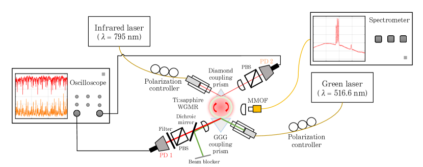
The main component of our experiment is the Ti:sapphire WGMR. After the fabrication process, the resonator was transferred to the experimental setup depicted in Figure 2. A green laser () is evanescently coupled into the resonator using a Gadolinium Gallium Garnet (GGG) prism ( = 1.96) [76]. The focus of the green laser is controlled using a graded index (GRIN) lens and a pigtailed ferrule. The distance between the prism and the resonator can be controlled using a piezo positioner with nanometer accuracy. Due to sapphire’s minimal birefringence, light can be coupled into both polarizations at the same angle, which makes it very easy to switch between the TE and TM polarizations using a three paddle polarization controller (PC), without realigning the beam. The output light from the prism is collimated using a lens and is split by a dichroic mirror into the green pump light and the fluorescence/lasing light. The green light is collected by a silicon (Si) photodiode (PD), whereas the lasing light is coupled into a single mode optical fibre (SMOF), via a collimating lens, aspheric collimator and two adjustable mirrors. A polarizing beam splitter (PBS) is placed right before the PD to confirm the polarization of the WGM. The PD is connected to an oscilloscope to monitor the WGMs. The output from the SMOF is coupled into an optical spectrum analyzer. Another Si PD is used to collect the surface scattered WGMR light to observe the WGM lasing. An optical filter is placed before this PD to make sure that it only collects the lasing light while filtering the scattered green light. A spectrometer together with a multi mode optical fibre (MMOF) is also used to observe the fluorescence spectrum of the resonator.
The pump powers reported in this work are the powers coupled into the resonator. The pigtailed ferrule utilized in the experiment is not designed for our pump wavelength, so it causes extra loss. Additionally, neither of the pigtailed ferrule, GRIN lens or GGG prism are coated. As the loss from these elements could be mitigated by specially designed replacements, we use the power at the resonator input (i.e., after one reflection of the prism). This power is calculated assuming the losses at the input and output of the prism are equal, as they are for Fresnel reflections. Imperfect mode matching of the pump beam to the pump whispering-gallery mode also reduces the power that enters the resonator. As an optimized prism coupling setup can achieve better than coupling efficiency [77], we have further corrected the power to be the power that actually enters the resonator. See the Supplement for further details on the powers used.
IV.3 Amplifier setup
After observing lasing in the Ti:sapphire resonator, we modified the experiment to observe amplification inside the WGMR stimulated by the pump and measure the gain. This modified setup is depicted in Figure 6. In order to observe the gain, we used another prism made from diamond ( [78]), together with the previously used GGG prism. The diamond prism is used to couple an infrared (IR) probe laser with a central wavelength of to one of the lasing WGMs. This wavelength lies within the gain range of the Ti:sapphire emission when it is pumped by a green laser.
Once the probe laser is coupled into the resonator and WGMs are observed, the pump laser is turned on to observe the probe amplification. Polarization controllers after both the green and the infrared lasers are used to switch between TE and TM polarizations. The position of the GGG prism is fixed during the process of data collection, whereas the diamond prism is moved away or towards the resonator, as the linewidth of the probe WGM is measured and recorded. The spectrometer is used to monitor the lasing excited by the green pump source. Two PDs are used to collect the output light from both prisms, with a PBS in front of each to monitor the polarization of the modes. The detectors are connected to the oscilloscope and are used to observe the resonances excited by the probe laser.
Supporting Information
Supporting Information is available.
Acknowledgements
We would like to thank Mathew Denys. We would like to acknowledge fruitful discussions with Jevon Longdell. We would like to thank Joseph Borbely and the Measurement Standards Laboratory of New Zealand (MSL). We would like to thank Brent Pooley and Malcolm Reid for their help in determining the titanium dopant concentration. AG would like to thank the Chinese National Science Fund for Talent Training in the Basic Sciences (No. J1103208) for sponsoring his visit to Otago. DVS and HGLS would like to thank the Ministry of Business, Innovation and Employment Catalyst Leaders fellowship (20-UOO-001-ILF).
References
- Moulton [1986] P. F. Moulton, Spectroscopic and laser characteristics of Ti:Al2O3, JOSA B 3, 125 (1986).
- Moulton [1992] P. F. Moulton, Tunable solid-state lasers, Proceedings of the IEEE 80, 348 (1992).
- Spence et al. [1991] D. E. Spence, P. N. Kean, and W. Sibbett, 60-fsec pulse generation from a self-mode-locked Ti:sapphire laser, Optics letters 16, 42 (1991).
- Gibson et al. [1996] G. Gibson, R. Klank, F. Gibson, and B. Bouma, Electro-optically cavity-dumped ultrashort-pulse Ti:sapphire oscillator, Optics Letters 21, 1055 (1996).
- Bartels et al. [2008] A. Bartels, D. Heinecke, and S. A. Diddams, Passively mode-locked 10 GHz femtosecond Ti:sapphire laser, Optics letters 33, 1905 (2008).
- Gürel et al. [2015] K. Gürel, V. J. Wittwer, M. Hoffmann, C. J. Saraceno, S. Hakobyan, B. Resan, A. Rohrbacher, K. Weingarten, S. Schilt, and T. Südmeyer, Green-diode-pumped femtosecond Ti:Sapphire laser with up to 450 mW average power, Optics Express 23, 30043 (2015).
- Naumov et al. [2005] S. Naumov, A. Fernandez, R. Graf, P. Dombi, F. Krausz, and A. Apolonski, Approaching the microjoule frontier with femtosecond laser oscillators, New Journal of Physics 7, 216 (2005).
- Kalashnikov et al. [2005] V. L. Kalashnikov, E. Podivilov, A. Chernykh, S. Naumov, A. Fernandez, R. Graf, and A. Apolonski, Approaching the microjoule frontier with femtosecond laser oscillators: theory and comparison with experiment, New Journal of Physics 7, 217 (2005).
- Kiriyama et al. [2009] H. Kiriyama, M. Mori, Y. Nakai, T. Shimomura, M. Tanoue, A. Akutsu, H. Okada, T. Motomura, S. Kondo, S. Kanazawa, et al., Generation of high-contrast and high-intensity laser pulses using an opcpa preamplifier in a double cpa, Ti:sapphire laser system, Optics Communications 282, 625 (2009).
- Sung et al. [2017] J. H. Sung, H. W. Lee, J. Y. Yoo, J. W. Yoon, C. W. Lee, J. M. Yang, Y. J. Son, Y. H. Jang, S. K. Lee, and C. H. Nam, 4.2 PW, 20 fs Ti:sapphire laser at 0.1 Hz, Optics letters 42, 2058 (2017).
- Matos et al. [2004] L. Matos, D. Kleppner, O. Kuzucu, T. Schibli, J. Kim, E. Ippen, and F. Kaertner, Direct frequency comb generation from an octave-spanning, prismless Ti:sapphire laser, Optics letters 29, 1683 (2004).
- Krausz and Ivanov [2009] F. Krausz and M. Ivanov, Attosecond physics, Reviews of Modern Physics 81, 163 (2009).
- Frietsch et al. [2013] B. Frietsch, R. Carley, K. Döbrich, C. Gahl, M. Teichmann, O. Schwarzkopf, P. Wernet, and M. Weinelt, A high-order harmonic generation apparatus for time-and angle-resolved photoelectron spectroscopy, Review of Scientific Instruments 84, 075106 (2013).
- Chiang et al. [2012] C.-T. Chiang, A. Blättermann, M. Huth, J. Kirschner, and W. Widdra, High-order harmonic generation at 4 Mhz as a light source for time-of-flight photoemission spectroscopy, Applied Physics Letters 101, 071116 (2012).
- He et al. [2013] L. He, Ş. K. Özdemir, and L. Yang, Whispering gallery microcavity lasers, Laser & Photonics Reviews 7, 60 (2013).
- Pelton et al. [2002] M. Pelton, J. Vukovic, G. S. Solomon, A. Scherer, and Y. Yamamoto, Three-dimensionally confined modes in micropost microcavities: quality factors and purcell factors, IEEE Journal of Quantum Electronics 38, 170 (2002).
- Kimble [1998] H. J. Kimble, Strong interactions of single atoms and photons in cavity QED, Physica Scripta 1998, 127 (1998).
- Özdemir et al. [2011] Ş. K. Özdemir, J. Zhu, L. He, and L. Yang, Estimation of purcell factor from mode-splitting spectra in an optical microcavity, Physical Review A 83, 033817 (2011).
- Bulović et al. [1998] V. Bulović, V. Kozlov, V. Khalfin, and S. Forrest, Transform-limited, narrow-linewidth lasing action in organic semiconductor microcavities, Science 279, 553 (1998).
- Spiegelberg et al. [2004] C. Spiegelberg, J. Geng, Y. Hu, Y. Kaneda, S. Jiang, and N. Peyghambarian, Low-noise narrow-linewidth fiber laser at 1550 nm (june 2003), Journal of Lightwave Technology 22, 57 (2004).
- François et al. [2016] A. François, N. Riesen, K. Gardner, T. M. Monro, and A. Meldrum, Lasing of whispering gallery modes in optofluidic microcapillaries, Optics express 24, 12466 (2016).
- François et al. [2015a] A. François, N. Riesen, H. Ji, S. Afshar. V, and T. M. Monro Polymer based whispering gallery mode laser for biosensing applications, Appl. Phys. Lett 106, 031104 (2015a).
- Wienhold et al. [2015] T. Wienhold, S. Kraemmer, S. Wondimu, T. Siegle, U. Bog, U. Weinzierl, S. Schmidt, H. Becker, H. Kalt, T. Mappes, et al., All-polymer photonic sensing platform based on whispering-gallery mode microgoblet lasers, Lab on a Chip 15, 3800 (2015).
- François et al. [2015b] A. François, T. Reynolds, and T. M. Monro, A fiber-tip label-free biological sensing platform: a practical approach toward in-vivo sensing, Sensors 15, 1168 (2015b).
- Strekalov et al. [2016] D. V. Strekalov, C. Marquardt, A. B. Matsko, H. G. L. Schwefel, and G. Leuchs, Nonlinear and quantum optics with whispering gallery resonators, Journal of Optics 18, 123002 (2016).
- Garrett et al. [1961] C. Garrett, W. Kaiser, and W. Bond, Stimulated emission into optical whispering modes of spheres, Physical Review 124, 1807 (1961).
- Carmon et al. [2005] T. Carmon, T. J. Kippenberg, L. Yang, H. Rokhsari, S. Spillane, and K. J. Vahala, Feedback control of ultra-high-Q microcavities: application to micro-raman lasers and micro-parametric oscillators, Optics Express 13, 3558 (2005).
- Grudinin et al. [2009] I. S. Grudinin, A. B. Matsko, and L. Maleki, Brillouin lasing with a CaF2 whispering gallery mode resonator, Physical review letters 102, 043902 (2009).
- Chu et al. [2011] Y. Chu, A. Mintairov, Y. He, J. Merz, N. Kalugnyy, V. Lantratov, and S. Mintairov, Lasing of whispering-gallery modes in GaInP waveguide micro-discs and rings with inp quantum dots, physica status solidi c 8, 325 (2011).
- Lacey et al. [2007] S. Lacey, I. M. White, Y. Sun, S. I. Shopova, J. M. Cupps, P. Zhang, and X. Fan, Versatile opto-fluidic ring resonator lasers with ultra-low threshold, Optics express 15, 15523 (2007).
- Rong et al. [2007] H. Rong, S. Xu, Y.-H. Kuo, V. Sih, O. Cohen, O. Raday, and M. Paniccia, Low-threshold continuous-wave raman silicon laser, Nature Photonics 1, 232 (2007).
- Min et al. [2003] B. Min, T. J. Kippenberg, and K. J. Vahala, Compact, fiber-compatible, cascaded raman laser, Optics letters 28, 1507 (2003).
- Ward and Benson [2011] J. Ward and O. Benson, WGM microresonators: sensing, lasing and fundamental optics with microspheres, Laser & Photonics Reviews 5, 553 (2011).
- Reynolds et al. [2017] T. Reynolds, N. Riesen, A. Meldrum, X. Fan, J. M. Hall, T. M. Monro, and A. François, Fluorescent and lasing whispering gallery mode microresonators for sensing applications, Laser & Photonics Reviews 11, 1600265 (2017).
- Rex et al. [2002] N. B. Rex, H. E. Türeci, H. G. L. Schwefel, R. K. Chang, and A. D. Stone, Fresnel filtering in lasing emission from scarred modes of wave-chaotic optical resonators, Physical Review Letters 88, 094102 (2002).
- Schwefel et al. [2004] H. G. L. Schwefel, N. B. Rex, H. E. Tureci, R. K. Chang, A. D. Stone, T. Ben-Messaoud, and J. Zyss, Dramatic shape sensitivity of directional emission patterns from similarly deformed cylindrical polymer lasers, Journal of the Optical Society of America B 21, 923 (2004).
- Gmachl et al. [1998] C. Gmachl, F. Capasso, E. E. Narimanov, J. U. Nöckel, A. D. Stone, J. Faist, D. L. Sivco, and A. Y. Cho, High-power directional emission from microlasers with chaotic resonators, Science 280, 1556 (1998).
- Nöckel and Stone [1997] J. U. Nöckel and A. D. Stone, Ray and wave chaos in asymmetric resonant optical cavities, Nature 385, 45 (1997).
- Gargas et al. [2010] D. J. Gargas, M. C. Moore, A. Ni, S.-W. Chang, Z. Zhang, S.-L. Chuang, and P. Yang, Whispering gallery mode lasing from zinc oxide hexagonal nanodisks, ACS nano 4, 3270 (2010).
- Herr et al. [2017] S. J. Herr, K. Buse, and I. Breunig, LED-pumped whispering-gallery laser, Photonics Research 5, B34 (2017).
- Fernandez-Bravo et al. [2018] A. Fernandez-Bravo, K. Yao, E. S. Barnard, N. J. Borys, E. S. Levy, B. Tian, C. A. Tajon, L. Moretti, M. V. Altoe, S. Aloni, et al., Continuous-wave upconverting nanoparticle microlasers, Nature nanotechnology 13, 572 (2018).
- Moiseev et al. [2018] E. Moiseev, N. Kryzhanovskaya, M. Maximov, F. Zubov, A. Nadtochiy, M. Kulagina, Y. Zadiranov, N. Kalyuzhnyy, S. Mintairov, and A. Zhukov, Highly efficient injection microdisk lasers based on quantum well-dots, Optics letters 43, 4554 (2018).
- Liang et al. [2015a] W. Liang, A. A. Savchenkov, Z. Xie, J. F. McMillan, J. Burkhart, V. S. Ilchenko, C. W. Wong, A. B. Matsko, and L. Maleki, Miniature multioctave light source based on a monolithic microcavity, Optica 2, 40 (2015a).
- Liang et al. [2015b] W. Liang, V. S. Ilchenko, D. Eliyahu, A. A. Savchenkov, A. B. Matsko, D. Seidel, and L. Maleki, Ultralow noise miniature external cavity semiconductor laser, Nature Communications 6, 7371 (2015b), number: 1 Publisher: Nature Publishing Group.
- Sprenger et al. [2009] B. Sprenger, H. G. L. Schwefel, and L. J. Wang, Whispering-gallery-mode-resonator-stabilized narrow-linewidth fiber loop laser, Opt. Lett. 34, 3370 (2009).
- Collodo et al. [2014] M. C. Collodo, F. Sedlmeir, B. Sprenger, S. Svitlov, L. J. Wang, and H. G. L. Schwefel, Sub-kHz lasing of a CaF2 whispering gallery mode resonator stabilized fiber ring laser, Optics Express 22, 19277 (2014).
- Kondratiev et al. [2017] N. M. Kondratiev, V. E. Lobanov, A. V. Cherenkov, A. S. Voloshin, N. G. Pavlov, S. Koptyaev, and M. L. Gorodetsky, Self-injection locking of a laser diode to a high-Q WGM microresonator, Optics Express 25, 28167 (2017).
- Hartnett et al. [1999] J. Hartnett, M. Tobar, A. Mann, E. Ivanov, J. Krupka, and R. Geyer, Frequency-temperature compensation in Ti3+ and Ti4+ doped sapphire whispering gallery mode resonators, IEEE Transactions on Ultrasonics, Ferroelectrics and Frequency Control 46, 993 (1999).
- Hartnett et al. [1998] J. Hartnett, M. Tobar, A. Mann, J. Krupka, and E. Ivanov, Temperature dependence of Ti3+ doped sapphire whispering gallery mode resonator, Electronics Letters 34, 195 (1998).
- Boubekeur et al. [2005] N. Boubekeur, J. Hartnett, M. Tobar, N. Bazin, Y. Kersalé, and V. Giordano, Frequency stability of Ti3+-doped whispering gallery mode sapphire resonator oscillator at 34 K, Electronics Letters 41, 534 (2005).
- Ilchenko et al. [2014] V. S. Ilchenko, A. A. Savchenkov, A. B. Matsko, and L. Maleki, Generation of kerr frequency combs in a sapphire whispering gallery mode microresonator, Optical Engineering 53, 122607 (2014).
- Mahnke et al. [2001] M. Mahnke, S. Wiechmann, H. Heider, O. Blume, and J. Müller, Aluminum oxide doped with erbium, titanium and chromium for active integrated optical applications, AEU-International Journal of Electronics and Communications 55, 342 (2001).
- Türeci et al. [2007] H. E. Türeci, A. D. Stone, and L. Ge, Theory of the spatial structure of nonlinear lasing modes, Physical Review A 76, 013813 (2007).
- Ge et al. [2008] L. Ge, R. J. Tandy, A. D. Stone, and H. E. Türeci, Quantitative verification of ab initio self-consistent laser theory, Optics Express 16, 16895 (2008).
- Aung et al. [2015] N. L. Aung, L. Ge, O. Malik, H. E. Türeci, and C. F. Gmachl, Threshold current reduction and directional emission of deformed microdisk lasers via spatially selective electrical pumping, Applied Physics Letters 107, 151106 (2015).
- Koechner and Bass [2006] W. Koechner and M. Bass, Solid-state lasers: a graduate text (Springer Science & Business Media, 2006).
- Albers et al. [1986] P. Albers, E. Stark, and G. Huber, Continuous-wave laser operation and quantum efficiency of titanium-doped sapphire, JOSA B 3, 134 (1986).
- Sanchez et al. [1988] A. Sanchez, A. J. Strauss, R. L. Aggarwal, and R. E. Fahey, Crystal growth, spectroscopy, and laser characteristics of Ti:Al2O3, IEEE journal of quantum electronics 24, 995 (1988).
- Rapoport and Khattak [1988] W. R. Rapoport and C. P. Khattak, Titanium sapphire laser characteristics, Applied Optics 27, 2677 (1988).
- Alfrey [1989] A. J. Alfrey, Modeling of longitudinally pumped CW Ti:sapphire laser oscillators, IEEE journal of quantum electronics 25, 760 (1989).
- Pinto et al. [1994] J. F. Pinto, L. Esterowitz, G. H. Rosenblatt, M. Kokta, and D. Peressini, Improved Ti:sapphire laser performance with new high figure of merit crystals, IEEE journal of quantum electronics 30, 2612 (1994).
- Joyce and Schmid [2010] D. B. Joyce and F. Schmid, Progress in the growth of large scale Ti:sapphire crystals by the heat exchanger method (HEM) for petawatt class lasers, Journal of crystal growth 312, 1138 (2010).
- Nehari et al. [2011] A. Nehari, A. Brenier, G. Panzer, K. Lebbou, J. Godfroy, S. Labor, H. Legal, G. Cheriaux, J. P. Chambaret, T. Duffar, et al., Ti-doped sapphire (Al2O3) single crystals grown by the kyropoulos technique and optical characterizations, Crystal growth & design 11, 445 (2011).
- Harrison et al. [1991] J. Harrison, A. Finch, D. M. Rines, G. A. Rines, and P. F. Moulton, Low-threshold, CW, all-solid-state Ti:Al2O3 laser, Optics letters 16, 581 (1991).
- Kowalevicz et al. [2002] A. Kowalevicz, T. Schibli, F. Kärtner, and J. Fujimoto, Ultralow-threshold kerr-lens mode-locked Ti:Al2O3 laser, Optics Letters 27, 2037 (2002).
- Roth et al. [2011] P. W. Roth, A. J. Maclean, D. Burns, and A. J. Kemp, Direct diode-laser pumping of a mode-locked Ti:sapphire laser, Optics Letters 36, 304 (2011).
- Wang et al. [2016] S.-C. Wang, C.-Y. Hsu, T.-T. Yang, D.-Y. Jheng, T.-I. Yang, T.-S. Ho, and S.-L. Huang, Laser-diode pumped glass-clad Ti:sapphire crystal fiber laser, Optics letters 41, 3217 (2016).
- Grivas et al. [2012] C. Grivas, C. Corbari, G. Brambilla, and P. G. Lagoudakis, Tunable, continuous-wave Ti:sapphire channel waveguide lasers written by femtosecond and picosecond laser pulses, Optics letters 37, 4630 (2012).
- Grivas et al. [2018] C. Grivas, R. Ismaeel, C. Corbari, C.-C. Huang, D. W. Hewak, P. Lagoudakis, and G. Brambilla, Generation of multi-gigahertz trains of phase-coherent femtosecond laser pulses in Ti:Sapphire waveguides, Laser & Photonics Reviews 12, 1800167 (2018).
- Roth et al. [2009] P. W. Roth, A. J. Maclean, D. Burns, and A. J. Kemp, Directly diode-laser-pumped Ti:sapphire laser, Optics Letters 34, 3334 (2009).
- Kemp [2021] A. J. Kemp, private communication (2021).
- Saleh and Teich [2007] B. E. A. Saleh and M. C. Teich, Fundamentals of Photonics (Wiley, 2007).
- Schwefel [2004] H. G. L. Schwefel, Directionality and Vector Resonances of Regular and Chaotic Dielectric Microcavities, Ph.D. thesis, Yale University, New Haven, USA, New Haven, CT (2004).
- Savchenkov et al. [2006] A. A. Savchenkov, A. B. Matsko, I. Grudinin, E. A. Savchenkova, D. Strekalov, and L. Maleki, Optical vortices with large orbital momentum: generation and interference, Optics express 14, 2888 (2006).
- Ilchenko et al. [2007] V. S. Ilchenko, M. Mohageg, A. A. Savchenkov, A. B. Matsko, and L. Maleki, Efficient generation of truncated bessel beams using cylindrical waveguides, Optics express 15, 5866 (2007).
- Wood and Nassau [1990] D. L. Wood and K. Nassau, Optical properties of gadolinium gallium garnet, Applied Optics 29, 3704 (1990).
- Strekalov et al. [2009] D. Strekalov, A. Savchenkov, A. Matsko, and N. Yu, Efficient upconversion of subterahertz radiation in a high-Q whispering gallery resonator, Optics letters 34, 713 (2009).
- Phillip and Taft [1964] H. R. Phillip and E. A. Taft, Kramers-Kronig Analysis of Reflectance Data for Diamond, Physical Review 136, A1445 (1964).