On electrically tunable stacking domains and ferroelectricity in moiré superlattices
Abstract
Abstract. It is well known that stacking domains form in moiré superlattices due to the competition between the interlayer van der Waals forces and intralayer elastic forces, which can be recognized as polar domains due to the local spontaneous polarization in bilayers without centrosymmetry. We propose a theoretical model which captures the effect of an applied electric field on the domain structure. The coupling between the spontaneous polarization and field leads to uneven relaxation of the domains, and a net polarization in the superlattice at nonzero fields, which is sensitive to the moiré period. We show that the dielectric response to the field reduces the stacking energy and leads to softer domains in all bilayers. We then discuss the recent observations of ferroelectricity in the context of our model.
pacs:
Valid PACS appear hereIntroduction
Twistronics, the study of layered systems with a relative twist angle or lattice mismatch between the layers, resulting in moiré superlattices, is one of the most exciting new topics in condensed matter physics. It was predicted about a decade ago that introducing a small relative twist in a layered system such as bilayer graphene could lead to flat electronic bands, and strongly correlated behaviormorell2010flat ; bistritzer2011moire . Moiré superlattices have since been shown to exhibit superconductivitycao2018unconventional ; yankowitz2019tuning , metal-insulator transitionscao2018correlated , as well as magneticsharpe2019emergent , topologicalyin2016direct ; rickhaus2018transport ; huang2018topologically ; sunku2018photonic and excitonicyu2017moire ; seyler2019signatures behavior, facilitated by the tuning of the twist angle or lattice mismatch. Recently, ferroelectricity was observed in bilayer graphenezheng2020unconventional and hexagonal boron nitride (hBN)stern2020interfacial , which is highly unusual, because the constituent materials are non-polar, and bilayer graphene is normally metallic. The ferroelectricity was found to be sensitive to the twist angle and lattice mismatch, with some samples exhibiting no hysteresis and some exhibiting strong hysteresis. The ferroelectricity is clearly very unconventional, and the physical mechanism is currently not well understood.
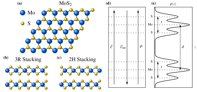
Structural phenomena in moiré superlattices are generally well understood. It is known that the interlayer separation ripples in space due to the local misalignment of the atoms, which can influence physical properties guinea2008gauge ; san2014spontaneous . Additionally, lattice relaxation occurs due to the competition between the in-plane strains and out-of-plane van der Waals interactions, leading to stacking domainsjung2015origin ; nam2017lattice ; zhang2018structural ; carr2018relaxation ; lebedeva2019commensurate ; lebedeva2019energetics ; lebedeva2020two . The elastic energy depends on the twist angle and lattice mismatch quadratically, meaning the domains can be tuned. The domain structures have been shown to have a large influence on the properties of the systemalden2013strain ; woods2014commensurate ; yankowitz2016pressure ; jung2015origin ; nam2017lattice ; carr2017twistronics ; zhang2018structural , leading to the opening of band gaps and enhanced Fermi velocity, for example. Polar effects have been given less consideration because the typical materials use to fabricate moiré superlattices, graphene, hBN and transition metal dichalcogenides (TMDs) such as (see Figs. 1 (a)-(c)), are non-polar.
There are two main mechanisms by which polar phenomena can manifest in moiré systems. The first is a local spontaneous out-of-plane polarizationli2017binary , which occurs in bilayers without centrosymmetry and averages to zero over the moiré period. The second is couplings between strain and polarization, namely piezoelectricitymcgilly2020visualization ; enaldiev2021piezoelectric ; ferreira2021weak and flexoelectricitymcgilly2020visualization ; mashkevich1957electrical ; tolpygo1962investigation ; indenbom1981flexoelectric ; kogan1964piezoelectric ; tagantsev1985theory ; zubko2013flexoelectric . The strain gradient is largest across the domain walls, and via flexoelectricity, they have an inherent polarization. The flexoelectric response in 2D materials can be estimated by measuring the potential drop across the wall of a nanotube in the large radius limitPhysRevB.90.201112 ; mcgilly2020visualization ; artyukhov2020flexoelectricity ; bennett2021flexoelectric , and it has been estimated that the flexoelectric coefficients in bilayer graphene is similar in magnitude to the clamped-ion flexoelectric response in oxide perovskitesmcgilly2020visualization ; PhysRevB.90.201112 ; dreyer2018current . The flexoelectric polarization is localized within the relatively narrow domain walls, however.
If we identify the stacking domains as polar domains via the two aforementioned mechanisms, then the stacking domains may serve as the basis for understanding polar phenomena in moiré materials. Thus, in order to understand the observed ferroelectricity, it is essential to understand how the stacking domains respond to an electric field. It is known that the domain structures in moiré materials can lead to interesting effects such as the opening of band gaps, and topologically protected states or channels when an electric field is appliedvaezi2013topological ; yin2016direct ; rickhaus2018transport ; huang2018topologically ; efimkin2018helical . To our knowledge, the influence of an applied electric field on the domains themselves has not been considered. It is known that an electric field can modify the interlayer separation and lead to a breakdown of TMD bilayers, for examplesantos2013electrically ; li2018asymmetric . The stacking domains are a result of lattice relaxation, which describes the delicate competition between the interlayer interactions and the intralayer elasticity. Since the interlayer interactions are sensitive to an applied field, it is reasonable to expect that the field would change the delicate balance and affect the resulting domain structure.
Results
In this paper, we introduce a model of lattice relaxation in a moiré superlattice which includes the effect of an applied field on the bilayer. The total energy is an integral of the energy density over a moiré supercell
| (1) |
where is the area of the supercell. For a bilayer system Eq. (1) is a discrete sum over atomic sites, but generalizes to a continuum field theory when the moiré period is much larger than the lattice constants of the monolayers.
We can model moiré superlattices at different levels of theory depending on the contributions we include in Eq. (1). The stacking energy captures the weak van der Waals interactions between the layers in terms of the layer separation . The elastic energy allows for in-plane displacements of the atoms in the layers. Together, the stacking and elastic energies provide a good description of the atomic structure in moiré superlattices, namely lattice relaxation and the formation of stacking domains. Having obtained a realistic description of the structure, one could proceed to obtain the electronic bands from tight-binding theory.
In order to consider the effect of an electric field on the atomic structure, we also include the electrostatic energy induced by an electric field perpendicular to the bilayer, see Fig. 1 (d). The total energy density is then
| (2) |
Each contribution is derived and discussed in detail in Section I of the supplementary information. In the elastic energy, summation is assumed, is the linear elasticity tensor and is the strain tensor, written in terms of a relative in-plane displacement .
The stacking energy can be included in a number of ways. The simplest is to use the cohesive energy as a function of space, , assuming that at each point in the supercell the layer separation takes the value that minimizes the local stacking energy: . Other studies have allowed the layer separation to vary by performing a harmonic expansion about the equilibrium layer separationguinea2008gauge . When considering the effect of an applied field, it is necessary to include the full van der Waals potential because some phenomena cannot be captured at the harmonic level, such as the breakdown of the bilayer for stronger fields santos2013electrically . A detailed study of the stacking energy of bilayer in the presence of an electric field, both theoretically and verified by first-principles calculations, is provided in Appendices A and B, respectively.
The first term in is the coupling between the electric field and the out-of-plane spontaneous dipole moment of the bilayerli2017binary . Bilayer systems without centrosymmetry, such as 3R (Fig. 1 (b)), have a local dipole moment throughout the supercell which averages to zero, whereas systems with centrosymmetry have no local dipole moment anywhere in the supercell, such as 2H (Fig. 1 (c)).
The second term describes the dielectric response of the bilayer to the electric field, where and are the first two coefficients in the expansion of the polarizability about the equilibrium layer separation. A bilayer system cannot simply be treated as a pair of capacitor plates; due to the overlap of states in the vacuum region between the layers, it is more appropriate to treat the system as a single slab with a nonuniform charge density, see Fig. 1 (e). Thus, changing the layer separation will affect the polarizability of the system, so we perform a Taylor expansion in . In Section II of the supplementary information we show with first-principles calculations that the polarizability is linear in . In addition, the polarizability will vary throughout the superlattice due to the different local stacking configurations and equilibrium layer separations. The dielectric response occurs in all layered systems, irrespective of symmetry.
The typical lattice relaxation procedure is as follows: the local energy densities in Eq. (2) are parameterized using first-principles calculations. Practically, this is done using the mapping between real space and ‘configuration space’ carr2018relaxation , where all of the local stacking configurations in real space are condensed into a single unit cell of relative translations between the layers (see Section II of the supplementary information). Configuration space can be traversed using first-principles calculations with only a single primitive cell (6 atoms for bilayer ), and translating one layer over the other. Quantities such as , , etc., can be parameterized in configuration space, and Eq. (1) can then be minimized with respect to the layer separation and in-plane displacements in order to obtain the relaxed structure.
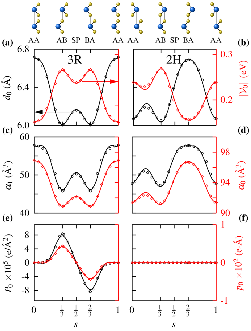
The parameterization of , , , and for 3R and 2H was done using siestasiesta and is shown in Fig. 2. Starting from the metal over metal configuration (AA), one layer was fixed and the other was translated along primitive cell diagonal in small increments, and the aforementioned quantities were measured at each point. By taking advantage of the rotation symmetry of the moiré superlattices, the data were interpolated by a low order 2D Fourier expansion throughout configuration space, greatly reducing the number of calculations required. The stacking energy and equilibrium layer separation both vary by about 1 Å / 0.1 eV, respectively, which is expected. We also found that both polarizability parameters vary significantly throughout the configuration space. Additionally, 3R has a small nonvanishing local dipole density with zero mean, see Fig. 2 (e), whereas 2H does not.
The lattice relaxation at finite electric fields was then performed in configuration space, including an additional in-plane displacement in the stacking and electrostatic energies, and minimizing the total energy numerically. The two terms in were included separately in order to illustrate their individual effects. The quadratic term does not break any symmetries, and thus we can study its effect on the domain structures by mapping the 2D moiré superlattice to a 1D Frenkel-Kontorova (FK) modelpopov2011commensurate ; lebedeva2016dislocations ; lebedeva2019commensurate , with a single domain wall across the path AB SP BA (see Section III of the supplementary information for more details). The linear term breaks the rotation symmetry of the 3R moiré superlattice, leading to a splitting between the AB and BA domains, which cannot be captured by a 1D FK model.
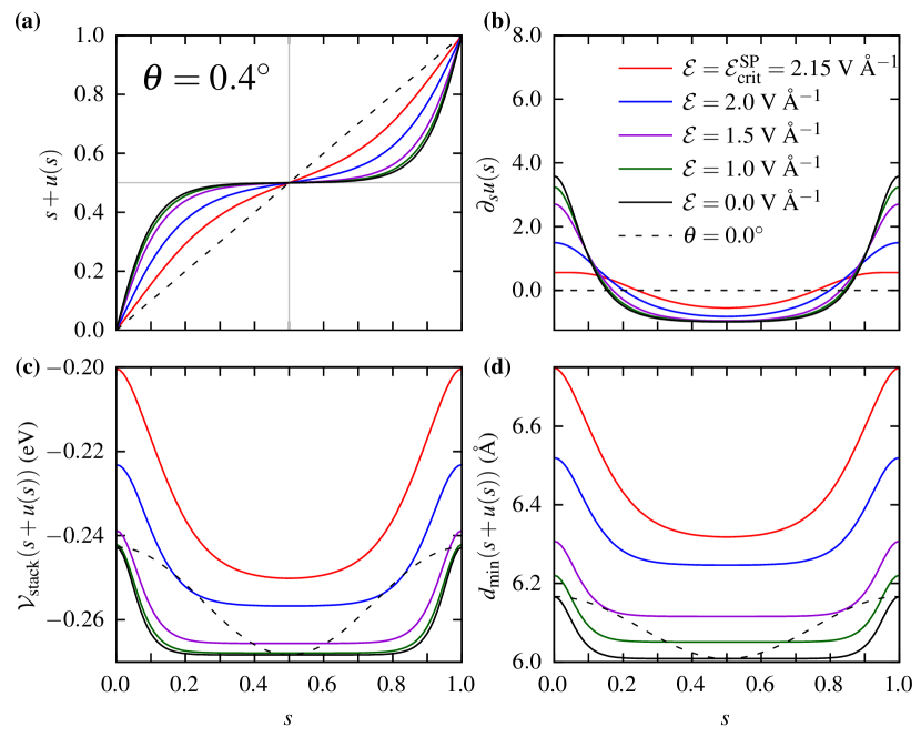
The 1D FK model, including only the dielectric response to the field, was solved for a fixed lattice mismatch , and for several values of electric field, see Fig. 3, with similar results at zero field for various lattice mismatches shown in Fig S10. At zero field, decreasing increases the displacement in between AB/BA and SP points, leading to a domain structure with wide AB/BA regions and narrow SP regions, separated by a domain wall, with width proportional to in configuration space. The domain structure is also evident from the stacking energy and equilibrium layer separation profile in configuration space, shown in Figs. 3 (c) and (d). When an electric field is applied, the equilibrium layer separation increases everywhere in configuration space, which decreases the stacking energy. With the stacking energy reduced, it is not as favorable for the atoms to relax; the displacement decreases, and the domain walls soften.
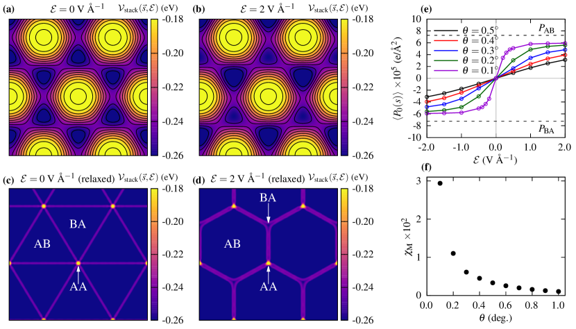
The 2D relaxation including only the coupling between the field and spontaneous polarization was done for a range of twist angles and field strengths V Å-1. The results are summarized in Fig. 4, and additional plots for all angles and electric field strengths can be found in Section IV of the supplementary information. In Figs 4 (a) and (b) we show the stacking energy in 3R in configuration space obtained from first-principles calculations, at electric field strengths of 0 and 2 V Å-1, respectively. The electric field increases the depth of the well at AB and decreases the depth of the well in BA by the same amount, breaking the rotation symmetry. The panels below, Figs 4 (c) and (d), show the corresponding stacking energies after lattice relaxation for a twist angle of . At zero field, the relaxation reduces the area of the AA regions and increases the area of the AB/BA regions, leading to a triangular domain structure with sharp domain walls. When an electric field is applied, the AB and BA regions relax unevenly, leading to larger AB regions and smaller BA regions reducing the rotation symmetry to . When the AB and BA domains are no longer equal in area, the polarization no longer averages to zero. In Fig. 4 (e) we show the average spontaneous polarization in configuration space as a function of field for different twist angles. We can see that the response to the field is very sensitive to the twist angle. In Fig. 4 (f) we show the susceptibility of the moiré superlattice as a function of twist angle, which was obtained by taking the slope of the polarization about zero field. We can see that the susceptibility increases dramatically as the twist angle decreases.
Discussion
We have introduced a model which illustrates the effect of an applied electric field on lattice relaxation in moiré superlattices. The model contains two electrostatic contributions. The first is a linear coupling between the field and the local spontaneous polarization in bilayers without centrosymmetry, which breaks the degeneracy between the AB and BA stacking domains. Under an electric field, the AB and BA regions will relax unevenly with one growing and the other shrinking with respect to the relaxed structure at zero field. This leads to a nonzero average out-of-plane polarization in the superlattice. The second contribution is the dielectric response to the field, which occurs in all bilayers. This term leads to a nonuniform increase the layer separation, which reduces stacking energy, leading to softer domains structures under lattice relaxation.
Finally, as our theory does not predict a ferroelectric response, we offer some thoughts on the recent experimental observations of ferroelectricity in the context of our model.
For a system to be considered ferroelectric, it (i) must exhibit a spontaneous polarization at zero field which (ii) must be switchable with an electric field. However, neither the individual stacking domains nor the moiré superlattice as a whole satisfy both conditions: The stacking domains indeed have a local spontaneous polarization at zero field, and while the average polarization of a domain can change via lattice relaxation under an electric field, the sign of the polarization in each cannot be switched. Therefore, the stacking domains in moiré superlattices are in general not ferroelectric. Conversely, the moiré superlattice itself exhibits an average polarization, the direction of which can be changed by the field, but has zero average polarization at zero field. Therefore, under ideal conditions, moiré superlattices are also not ferroelectric.
This idealized picture may not hold in experimental settings, and defects, mislocations or strain induced by the finite size of samples may lead to uneven domains at zero field. Also, the direct couplings between strain and polarization, piezoelectricity and flexoelectricity, have not been considered, which may make it energetically favourable for the domains to relax unevenly and the superlattice to have a nonzero average polarization at zero field. We leave the consideration of these effects for future work. To summarize, for an ideal system, when considering the spontaneous local polarization and lattice relaxation under an electric field, neither the moiré superlattice nor the stacking domains are ferroelectric, since the former does not have a spontaneous polarization at zero field and the latter does not have a switchable polarization.
There have also been reports of a switching of the polarization in a single stacking domain by a sliding of the atoms by half a monolayer lattice constant when a local field was applied to the domain using a biased atomic force microscopy (AFM) tip stern2020interfacial . This sliding change the stacking configuration: AB BA, leading to a first order switching of the polarization. This is a separate mechanism to the one mediated by lattice relaxation, which results in a second order change in the polarization. We can understand this sliding in the context of our model. When a field is applied to the domain, the linear coupling between the field and polarization will lower the energy if the two are aligned and result in a large energy penalty if they are anti-aligned. In either case, the dielectric response will reduce the stacking energy by the same amount, making it easier for one layer to slide with respect to the other. When the field and polarization are anti-aligned, the energy can be lowered considerably via a sliding by half a monolayer unit cell, flipping the polarization so that it becomes aligned with the field. However, the field is applied to the domain locally via an AFM tip, and it is not clear whether the sliding occurs locally under the tip, or throughout the entire domain. It is also not clear whether or not the domain will remain flipped once the field is removed, or relax back to its original orientation. Thus, it is not clear whether or not this mechanism for a first order switching of polarization in a stacking domain is truly ferroelectric either.
The model introduced in this paper illustrates, clearly and intuitively, the effect an electric field can have on lattice relaxation in moiré superlattices. We propose an electric field as a third quantity with which the domain structures in moiré superlattices can be tuned. Unlike the twist angle and lattice mismatch which are fixed for a given sample, an electric field can be applied dynamically to tune a sample in-situ. Thus, it may serve as a more practical approach to achieve control in moiré superlattices. We have also discussed how our theoretical model can be used to understand the recent observations of ferroelectricity in moiré superlattices. We believe it is inaccurate to consider moiré materials to be truly ferroelectric via lattice relaxation or sliding under an electric field. However, this motivates further study into polar phenomena in moiré materials.
Methods
First-principles calculations
First-principles density functional theory (DFT) calculations were performed using the siesta codesiesta using PSMLpsml norm-conservingnorm_conserving pseudopotentials, obtained from pseudo-dojopseudodojo . siesta employs a basis set of numerical atomic orbitals (NAOs)siesta ; siesta_2 , and double- polarized (DZP) orbitals were used for all calculations. The basis sets were optimised by hand, following the methodology in Ref. [basis_water, ].
A mesh cutoff of was used for the real space grid in all calculations. A Monkhorst-Pack -point gridmp of was used for the initial geometry relaxations, and a mesh of was used to calculate polarizabilities. Calculations were converged until the relative changes in the Hamiltonian and density matrix were both less than . For the geometry relaxations, the atomic positions were fixed in the in-plane directions, and the vertical positions and in-plane stresses were allowed to relax until the force on each atom was less than . The layer separation was taken to be the distance between the carbon atoms in bilayer graphene an the distance between the metals in bilayer (see Fig 1 (e)), and the stacking energy is calculated as , where and are the total energies of the bilayer and monolayer systems, respectively. The polarizability to zeroth order in , , was obtained by fixing the relaxed geometry, applying an electric field large enough to overcome internal field effects, and measuring the change in the out-of-plane dipole moment of the bilayer. The polarizability to first order in , , was obtained by changing the layer separation by with respect to and measuring the relative change in the polarizability. A detailed first-principles study is provided in Section II of the supplementary information.
Lattice Relaxation
Eq. (1) can be minimized by using variational methods and solving the resulting differential equations. This can be relatively demanding in 2D. Instead, we minimized the total energy using numerical optimization methods. Eq. (1) is a functional of the in-plane displacement in configuration space. If we perform a plane-wave expansion, , where are the reciprocal lattice vectors of the commenusrate bilayer, then the total energy becomes a function of , and can be minimized numerically with respect to the coefficients: . This was done in Julia, using the Optim package to do the optimization.
We can take advantage of the symmetry of our model to greatly reduce the number of independent vectors:
| (3) |
When there is a symmetry, i.e. for 3R at zero field, we have , and the cosine terms vanish. The optimization was done using the independent in the first five shells (10 vectors) for , six shells (21 vectors) for and and seven shells (28 vectors) for . The total energy was optimized using the limited memory BFGS algorithm (L-BFGS), until the gradient was below .
Data Availability. The data presented were generated from first-principles and lattice relaxation calculations as described in the text.
Code Availability. Code is available upon reasonable request.
Acknowledgements. D. B would like to thank E. Artacho and I. Lebedeva for helpful discussions. D. B acknowledges funding from the EPSRC Centre for Doctoral Training in Computational Methods for Materials Science under grant number EP/L015552/1. B. R gratefully acknowledges support from the Cambridge International Trust.
Author Contributions. D. B. conceived the project and performed the first-principles calculations. D. B. and B. R. developed the theoretical model and performed the lattice relaxation calculations. D. B. wrote the manuscript, with contributions from B. R.
Competing Interests. The authors declare no competing interests.
References
- (1) Morell, E. S., Correa, J., Vargas, P., Pacheco, M. & Barticevic, Z. Flat bands in slightly twisted bilayer graphene: Tight-binding calculations. Phys. Rev. B 82, 121407 (2010).
- (2) Bistritzer, R. & MacDonald, A. H. Moiré bands in twisted double-layer graphene. Proceedings of the National Academy of Sciences 108, 12233–12237 (2011).
- (3) Cao, Y. et al. Unconventional superconductivity in magic-angle graphene superlattices. Nature 556, 43–50 (2018).
- (4) Yankowitz, M. et al. Tuning superconductivity in twisted bilayer graphene. Science 363, 1059–1064 (2019).
- (5) Cao, Y. et al. Correlated insulator behaviour at half-filling in magic-angle graphene superlattices. Nature 556, 80–84 (2018).
- (6) Sharpe, A. L. et al. Emergent ferromagnetism near three-quarters filling in twisted bilayer graphene. Science 365, 605–608 (2019).
- (7) Yin, L.-J., Jiang, H., Qiao, J.-B. & He, L. Direct imaging of topological edge states at a bilayer graphene domain wall. Nature communications 7, 1–6 (2016).
- (8) Rickhaus, P. et al. Transport through a network of topological channels in twisted bilayer graphene. Nano letters 18, 6725–6730 (2018).
- (9) Huang, S. et al. Topologically protected helical states in minimally twisted bilayer graphene. Phys. Rev. Lett. 121, 037702 (2018).
- (10) Sunku, S. et al. Photonic crystals for nano-light in moiré graphene superlattices. Science 362, 1153–1156 (2018).
- (11) Yu, H., Liu, G.-B., Tang, J., Xu, X. & Yao, W. Moiré excitons: From programmable quantum emitter arrays to spin-orbit–coupled artificial lattices. Science advances 3, e1701696 (2017).
- (12) Seyler, K. L. et al. Signatures of moiré-trapped valley excitons in mose 2/wse 2 heterobilayers. Nature 567, 66–70 (2019).
- (13) Zheng, Z. et al. Unconventional ferroelectricity in moiré heterostructures. Nature 588, 71–76 (2020).
- (14) Stern, M. V. et al. Interfacial ferroelectricity by van der waals sliding. Science (2021).
- (15) Guinea, F., Horovitz, B. & Le Doussal, P. Gauge field induced by ripples in graphene. Phys. Rev. B 77, 205421 (2008).
- (16) San-Jose, P., Gutiérrez-Rubio, A., Sturla, M. & Guinea, F. Spontaneous strains and gap in graphene on boron nitride. Phys. Rev. B 90, 075428 (2014).
- (17) Jung, J., DaSilva, A. M., MacDonald, A. H. & Adam, S. Origin of band gaps in graphene on hexagonal boron nitride. Nature communications 6, 1–11 (2015).
- (18) Nam, N. N. & Koshino, M. Lattice relaxation and energy band modulation in twisted bilayer graphene. Phys. Rev. B 96, 075311 (2017).
- (19) Zhang, K. & Tadmor, E. B. Structural and electron diffraction scaling of twisted graphene bilayers. Journal of the Mechanics and Physics of Solids 112, 225–238 (2018).
- (20) Carr, S. et al. Relaxation and domain formation in incommensurate two-dimensional heterostructures. Phys. Rev. B 98, 224102 (2018).
- (21) Lebedeva, I. V. & Popov, A. M. Commensurate-incommensurate phase transition and a network of domain walls in bilayer graphene with a biaxially stretched layer. Phys. Rev. B 99, 195448 (2019).
- (22) Lebedeva, I. V. & Popov, A. M. Energetics and structure of domain wall networks in minimally twisted bilayer graphene under strain. The Journal of Physical Chemistry C 124, 2120–2130 (2019).
- (23) Lebedeva, I. V. & Popov, A. M. Two phases with different domain wall networks and a reentrant phase transition in bilayer graphene under strain. Phys. Rev. Lett. 124, 116101 (2020).
- (24) Alden, J. S. et al. Strain solitons and topological defects in bilayer graphene. Proceedings of the National Academy of Sciences 110, 11256–11260 (2013).
- (25) Woods, C. et al. Commensurate–incommensurate transition in graphene on hexagonal boron nitride. Nature physics 10, 451–456 (2014).
- (26) Yankowitz, M., Watanabe, K., Taniguchi, T., San-Jose, P. & LeRoy, B. J. Pressure-induced commensurate stacking of graphene on boron nitride. Nature communications 7, 1–8 (2016).
- (27) Carr, S. et al. Twistronics: Manipulating the electronic properties of two-dimensional layered structures through their twist angle. Phys. Rev. B 95, 075420 (2017).
- (28) Li, L. & Wu, M. Binary compound bilayer and multilayer with vertical polarizations: two-dimensional ferroelectrics, multiferroics, and nanogenerators. ACS nano 11, 6382–6388 (2017).
- (29) McGilly, L. J. et al. Visualization of moiré superlattices. Nature Nanotechnology 15, 580–584 (2020).
- (30) Enaldiev, V., Ferreira, F., Magorrian, S. & Fal’ko, V. I. Piezoelectric networks and ferroelectric domains in twistronic superlattices in ws2/mos2 and wse2/mose2 bilayers. 2D Materials 8, 025030 (2021).
- (31) Ferreira, F., Enaldiev, V., Fal’ko, V. & Magorrian, S. Weak ferroelectric charge transfer in layer-asymmetric bilayers of 2d semiconductors. Sci. Rep. 11 (2021).
- (32) Mashkevich, V. & Tolpygo, K. Electrical, optical and elastic properties of diamond type crystals. Sov. Phys. JETP 5, 435–439 (1957).
- (33) Tolpygo, K. Investigation of long-wavelength vibrations of diamond-type crystals with an allowance for long-range forces. Sov. Phys.—Solid States 4, 1765–1777 (1962).
- (34) Indenbom, V., Loginov, E. & Osipov, M. Flexoelectric effect and crystal-structure. Kristallografiya 26, 1157–1162 (1981).
- (35) Kogan, S. M. Piezoelectric effect during inhomogeneous deformation and acoustic scattering of carriers in crystals. Soviet Physics-Solid State 5, 2069–2070 (1964).
- (36) Tagantsev, A. Theory of flexoelectric effect in crystals. Zhurnal Eksperimental’noi i Teoreticheskoi Fiziki 88, 2108–22 (1985).
- (37) Zubko, P., Catalan, G. & Tagantsev, A. K. Flexoelectric effect in solids. Annual Review of Materials Research 43 (2013).
- (38) Stengel, M. Surface control of flexoelectricity. Phys. Rev. B 90, 201112 (2014). URL https://link.aps.org/doi/10.1103/PhysRevB.90.201112.
- (39) Artyukhov, V. I., Gupta, S., Kutana, A. & Yakobson, B. I. Flexoelectricity and charge separation in carbon nanotubes. Nano letters 20, 3240–3246 (2020).
- (40) Bennett, D. Flexoelectric-like radial polarization of single-walled nanotubes from first-principles. Electronic Structure 3, 015001 (2021).
- (41) Dreyer, C. E., Stengel, M. & Vanderbilt, D. Current-density implementation for calculating flexoelectric coefficients. Phys. Rev. B 98, 075153 (2018).
- (42) Vaezi, A., Liang, Y., Ngai, D. H., Yang, L. & Kim, E.-A. Topological edge states at a tilt boundary in gated multilayer graphene. Phys. Rev. X 3, 021018 (2013).
- (43) Efimkin, D. K. & MacDonald, A. H. Helical network model for twisted bilayer graphene. Phys. Rev. B 98, 035404 (2018).
- (44) Santos, E. J. & Kaxiras, E. Electrically driven tuning of the dielectric constant in mos2 layers. ACS nano 7, 10741–10746 (2013).
- (45) Li, L. H., Tian, T., Cai, Q., Shih, C.-J. & Santos, E. J. Asymmetric electric field screening in van der waals heterostructures. Nature communications 9, 1–11 (2018).
- (46) Soler, J. M. et al. The SIESTA Method for Ab Initio Order- Materials Simulation. Journal of Physics: Condensed Matter 14, 2745 (2002).
- (47) Popov, A. M., Lebedeva, I. V., Knizhnik, A. A., Lozovik, Y. E. & Potapkin, B. V. Commensurate-incommensurate phase transition in bilayer graphene. Phys. Rev. B 84, 045404 (2011).
- (48) Lebedeva, I. V., Lebedev, A. V., Popov, A. M. & Knizhnik, A. A. Dislocations in stacking and commensurate-incommensurate phase transition in bilayer graphene and hexagonal boron nitride. Phys. Rev. B 93, 235414 (2016).
- (49) García, A., Verstraete, M. J., Pouillon, Y. & Junquera, J. The psml format and library for norm-conserving pseudopotential data curation and interoperability. Computer Physics Communications 227, 51–71 (2018).
- (50) Hamann, D. Optimized norm-conserving vanderbilt pseudopotentials. Phys. Rev. B 88, 085117 (2013).
- (51) Van Setten, M. et al. The pseudodojo: Training and grading a 85 element optimized norm-conserving pseudopotential table. Computer Physics Communications 226, 39–54 (2018).
- (52) Artacho, E., Sánchez-Portal, D., Ordejón, P., Garcia, A. & Soler, J. M. Linear-scaling ab-initio calculations for large and complex systems. physica status solidi (b) 215, 809–817 (1999).
- (53) Corsetti, F., Fernández-Serra, M.-V., Soler, J. M. & Artacho, E. Optimal finite-range atomic basis sets for liquid water and ice. Journal of Physics: Condensed Matter 25, 435504 (2013). URL https://doi.org/10.1088%2F0953-8984%2F25%2F43%2F435504.
- (54) Monkhorst, H. J. & Pack, J. D. Special Points for Brillouin-Zone Integrations. Phys. Rev. B 13, 5188 (1976).