High-fidelity three-qubit iToffoli gate for fixed-frequency superconducting qubits
Abstract
The development of noisy intermediate-scale quantum (NISQ) devices has extended the scope of executable quantum circuits Preskill18 ; Bharti21 with high-fidelity single- and two-qubit gates Sung21 ; Kandala20 ; Brad21 ; Wei21 . Equipping NISQ devices with three-qubit gates will enable the realization of more complex quantum algorithms Haner17 ; Gidney21 ; Figgatt17 and efficient quantum error correction protocols Reed12 ; Paetznick13 ; Yoder16 with reduced circuit depth. Several three-qubit gates have been implemented for superconducting qubits Fedorov12 ; Reed12 ; Hill21 , but their use in gate synthesis has been limited due to their low fidelity. Here, using fixed-frequency superconducting qubits, we demonstrate a high-fidelity Toffoli gate based on two-qubit interactions, the so-called cross-resonance effect Rigetti10 ; Chow11 . As with the Toffoli gate, this three-qubit gate can be used to perform universal quantum computation Toffoli80 ; Shi03 ; Aharonov03 . The Toffoli gate is implemented by simultaneously applying microwave pulses to a linear chain of three qubits, revealing a process fidelity as high as 98.26(2)%. Moreover, we numerically show that our gate scheme can produce additional three-qubit gates which provide more efficient gate synthesis than the Toffoli and Toffoli gates. Our work not only brings a high-fidelity Toffoli gate to current superconducting quantum processors but also opens a pathway for developing multi-qubit gates based on two-qubit interactions.
The three-qubit Toffoli gate is universal for reversible classical computation, enabling arbitrary Boolean operations over quantum registers Toffoli80 . Moreover, together with the Hadamard gate, it forms a universal quantum gate set Shi03 ; Aharonov03 . Appending the Toffoli gate to a gate set consisting of the CNOT and single-qubit gates is practically helpful for reducing the overhead of gate synthesis. For instance, both the overall gate count and the circuit depth can be reduced by a factor of in Shor’s algorithm, which factorizes -bit integers Haner17 ; Gidney21 . The oracle functions of Grover’s search algorithm Figgatt17 and quantum error correction protocols Yoder16 ; Paetznick13 ; Reed12 can also be constructed with reduced resource costs. However, implementing a high-fidelity Toffoli gate is experimentally challenging; thus, the operation is usually realized by decomposing it into single- and two-qubit gates Figgatt17 ; Figgatt19 . This decomposition requires at least five two-qubit gates for fully connected qubits Barenco95 ; Yu13 and eight for nearest-neighbor connected qubits Smith21 , considerably reducing its fidelity.
Native Toffoli gates have been implemented by exploiting specific features of each quantum computing platform, such as the common vibrational mode of ion strings Monz09 , Rydberg blockade of neutral atoms Levine19 , and electron spin resonance of quantum dots Hendrickx21 . In superconducting circuits, the second or third excited states of frequency-tunable qubits have been employed Fedorov12 ; Reed12 ; Hill21 , but the best fidelity was limited to 87% as higher energy levels are generally more susceptible to decoherence and state leakage. Although a high-fidelity Toffoli gate has been recently reported using all-to-all intermodal couplings of multimode superconducting circuits Roy20 , the multimode architecture restricts the scalability of the gate. Additionally, there are proposals based on the degeneracy of excited-state manifolds Khazali20 , Hamiltonian engineering Zahedinejad15 , or strong Ising-type couplings Rasmussen20 , which are challenging to implement experimentally.
Here, we demonstrate a high-fidelity Toffoli gate by simultaneously driving three superconducting qubits at the same frequency. The simplicity of our scheme makes the gate calibration straightforward, and the gate can even be implemented on cloud-based quantum processors IBM . Similar to the Toffoli gate, the Toffoli gate inverts a target qubit conditioned upon two control qubits but with a phase shift of . This three-qubit gate can also be used for arbitrary Boolean operations Toffoli80 and forms a universal quantum gate set with the Hadamard gate Aharonov03 . To characterize our gate performance independently of state-preparation-and-measurement (SPAM) errors, we leverage cycle benchmarking Erhard19 and measure a process fidelity of 98.26(2)%. By analyzing the error budget, we find that the fidelity could be further improved using recently developed schemes to suppress undesired longitudinal interactions Kandala20 ; Brad21 ; Wei21 . In addition, our numerical study shows that our gate scheme is capable of generating additional three-qubit gates that synthesize random unitary circuits with a lower circuit depth compared to the Toffoli and Toffoli gates.

Schematic of the iToffoli gate
The Toffoli gate is performed on the three fixed-frequency transmons Koch07 shown in Fig. 1a. We use the left and right transmons as the control qubits and the center one as the target qubit, labeled , , and accordingly. The device parameters and the experimental setup are presented in Methods and Supplementary Note 1, respectively. The Toffoli gate is implemented by simultaneously applying microwave pulses to the three qubits at the target qubit frequency . The microwave tones on the control qubits induce the cross-resonance effect Rigetti10 ; Chow11 between and that manifests the interaction Hamiltonians , while the tone on the target qubit results in and rotations. , , and represent the Pauli operators for qubit . Taken together, the Hamiltonian of the driven three-qubit system is,
| (1) |
where and depend linearly on the amplitude of the control drives, and and are determined by the target drive’s amplitude and phase. Here we have omitted and terms, caused by the off-resonant control drives, as they can be removed at no cost using virtual Z gates McKay17 .
A Toffoli-like gate is implemented if undergoes a rotation about the -axis on the Bloch sphere for a certain control state and remains invariant otherwise. To explore the conditional evolution of , we reduce the Hamiltonian in Eq. (1) into the effective target Hamiltonian depending on control state :
| (2) |
Although the conditional inverting operation can be realized for any control state with these Hamiltonians, in this work, we demonstrate the conditional operation for . Specifically, we consider the scheme in which rotates by when the control state is and by otherwise. This can be accomplished by first imposing to make the conditional Rabi frequencies of the same except for : for and for the other control states. Then, we can make with , and a Toffoli-like gate is realized by setting the gate duration to .
Figure 1b shows the conditional evolution of from the initial state . Due to the Pancharatnam-Berry geometric phase Jordan88 ; Cho19 , the target qubit accumulates a phase for control state and a phase for the other control states, making the operation the Toffoli gate rather than the conventional Toffoli gate. Although the rotation axis for is not aligned along the -axis, this axis can effectively be transformed onto the -axis by sandwiching the three-qubit operation with virtual Z gates on the target qubit. The circuit diagram of the Toffoli operation is shown in Fig. 1c. The Toffoli gate differs from the Toffoli gate only by a controlled-phase gate Selinger13 .
Gate operation and geometric phase error
We now turn to the experimental implementation of the Toffoli gate. For the gate operation, as shown in Fig 2a, we use microwave pulses with a flat-top envelope and 30-ns cosine ramps. The pulses are applied at the target qubit frequency for pulse duration . The gate calibration is conducted by tuning the amplitude and phase of each pulse to make the conditional Rabi frequencies . The calibration procedure is detailed in Methods. Figure 2b shows the experimental results of the conditional Rabi oscillations starting from , and the Toffoli gate is implemented at .
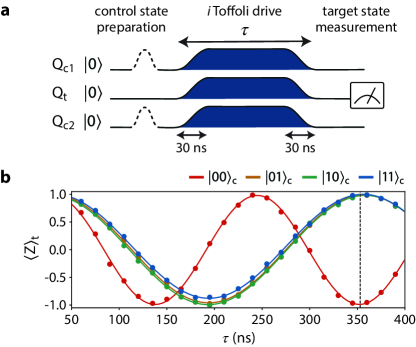
The oscillation amplitudes of less than 1 in Fig. 2b indicate that the rotation axis is not in the -plane. The axial tilt is mainly due to parasitic longitudinal (ZZ) interactions between nearest-neighbor qubits Tripathi19 ; Magesan20 . These undesired interactions add a conditional term to the effective target Hamiltonians in Eq. (2) for each control state . This is detrimental to the Toffoli gate as a non-zero induces a different geometric phase (GP) for and . Note that the GP is given by for a trajectory on the Bloch sphere, where is the angle between the state vector and the rotation axis and denotes the rotation angle Jordan88 ; Cho19 . Considering the rotation axis tilted by undesired interactions, is for and for . Thus, in the absence of qubit decoherence, the Toffoli operation maps the computational basis states as follows:
| (3) |
where . In the case of , is presumed to be zero so that the target qubit’s computational states are perfectly inverted with a phase shift of . The condition is satisfied if the drive tones are at the target qubit frequency . We estimate the GP error in to be by obtaining from the oscillation amplitudes in Fig. 2b. Here the entanglement fidelity is adopted as the measure of the process fidelity, where is the Hilbert space dimension Nielsen02 .
Gate benchmark and error budget analysis
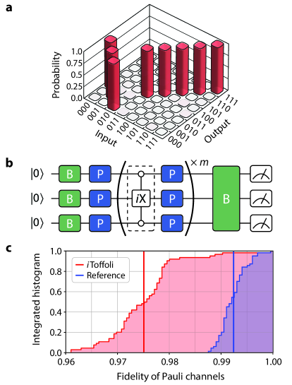
As an initial characterization of the Toffoli gate, the classical truth table is obtained for the computational states after correcting the readout errors based on the readout fidelities Nachman20 (see Fig. 3a). This table shows that the target state is inverted only when the control state is . The process fidelity of the truth table , excluding the GP error, is given as with respect to the ideal operation . The uncertainty is obtained by performing 1000 Monte Carlo simulation runs taking into account statistical errors. The population leakage to the second excited state is measured to be less than 0.1% for all the qubits.
The fidelity measured above is subject to state-preparation-and-measurement (SPAM) errors. To extract a SPAM-error-free fidelity estimate of a quantum operation, interleaved randomized benchmarking (IRB) is typically used Magesan11 ; Magesan12 ; Morvan21 . However, IRB is impractical for the Toffoli gate due to the complexity of three-qubit Clifford twirling McKay19 . As an alternative, we perform cycle benchmarking (CB) which relies on Pauli twirling Erhard19 . The CB protocol has better scalability than IRB as the complexity of twirling operation is reduced. The circuit schematic of the CB protocol is depicted in Fig. 3b. The Pauli twirling of the Toffoli gate tailors the gate errors to stochastic Pauli error channels, and the initial state and measurement basis are chosen to pick up a Pauli channel using True-Q Beale20 .
We run CB for all three-qubit Pauli channels with depth and 30 samples for each . In order to decouple SPAM errors from fidelity estimate, the fidelity of each Pauli channel is extracted by fitting the fidelity decay to an exponential model . However, since the fidelity still includes the error from Pauli-twirling operations, the Pauli-twirling error needs to be separately estimated by performing CB without the Toffoli gate as a reference. Figure 3c shows the cumulative fidelity histograms of all three-qubit Pauli channels for the Pauli-twirled Toffoli gate and the reference . The fidelity of each Pauli channel is exhibited in Supplementary Note 2. From the results, the process fidelity of the Toffoli gate is estimated to be by averaging over all the Pauli channels Erhard19 . The uncertainty represents the fitting errors of fidelity decays.
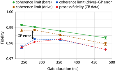
Additionally, to get insights into factors limiting improvement in process fidelity, we perform CB for Toffoli gates having different gate durations and analyze the error budget. As the error sources, the geometric phase (GP) error and decoherence of the qubits are considered. The GP error is estimated according to Eq. (3), and the coherence-limited infidelity Dawkins20 is evaluated using the relaxation () and the Hahn-echo dephasing () times of each qubit and the gate duration. See Methods for the calculation of coherence-limited infidelity. We experimentally observed that the of and are reduced under the Toffoli drive relative to the bare coherence times. Accordingly, we calculated the coherence limits using both the bare coherence times and the coherence times under drive. The measurement sequences and data of the coherence times are presented in Supplementary Note 3. Figure 4 shows that the process fidelities obtained from CB are well explained by the estimated error budget. The results reveal that undesired longitudinal interactions, or the GP errors, increase with decreasing gate duration, limiting further reduction in gate duration and improvement in process fidelity.
Gate synthesis of three-qubit circuits
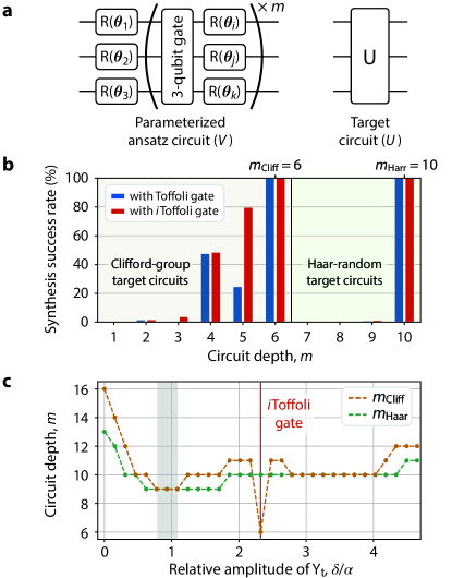
Finally, we numerically explore gate synthesis of three-qubit circuits to demonstrate the utility of the Toffoli gate. To this end, we consider an ansatz circuit depicted in Fig. 5a with depth . The gate synthesis of a target circuit is conducted by optimizing the ansatz parameters to minimize the distance between and , or their infidelity . The simulation results in Fig. 5b show that both Toffoli and Toffoli gates can be used to synthesize arbitrary three-qubit Clifford circuits at and Haar-random unitary circuits at . Additionally, the results indicate that the ansatz circuit with the Toffoli gate can synthesize more various target circuits at lower depths than the Toffoli gate.
Furthermore, we estimate threshold depths and of our gate scheme by varying ’s amplitude in the Hamiltonian of Eq. (1). For this simulation, the other Hamiltonian amplitudes and the gate duration are fixed to the same values used for implementing the Toffoli gate. As is the only non-commuting term in the Hamiltonian, it plays a key role in preventing the Hamiltonian operation from being a simple combination of single- and two-qubit gates. Interestingly, the results in Fig. 5c reveal that, over a range of values, our gate scheme can produce three-qubit gates which synthesize random unitary circuits at . That is, while the structured Toffoli and Toffoli gates have advantages for Clifford circuits, these alternative three-qubit gates could be beneficial for implementing random unitary circuits.
Discussion and outlook
We have demonstrated a single-step Toffoli gate scheme based on the cross-resonance (CR) effect with fixed-frequency transmon qubits.
As the CR effect can readily be implemented between capacitively coupled superconducting qubits Rigetti10 ; Chow11 , our scheme is applicable to a number of superconducting architectures including cloud-based quantum processors IBM . In our gate scheme, the non-commuting term in Eq. (1) plays a key role in preventing the full Hamiltonian operation from being decomposable into simple consecutive operations. By varying the amplitude of the term, we have numerically found that this gate scheme can produce additional three-qubit gates providing more efficient gate synthesis than both the Toffoli and Toffoli gates. We hope our work will trigger further studies to develop diverse multi-qubit gates derived from two-qubit interactions involving non-commuting Hamiltonian operators.
To characterize a 353-ns Toffoli gate without state-preparation-and-measurement (SPAM) errors, we have leveraged cycle benchmarking and measured a process fidelity of 98.26(2)%. The infidelity is primarily due to decoherence of the qubits and undesired longitudinal (ZZ) interactions. By analyzing the error budget, we have found that such undesired interactions limit a further improvement in process fidelity. Recently, the multi-path coupling scheme Kandala20 and the microwave-induced ZZ tuning scheme Brad21 ; Wei21 have been demonstrated to suppress ZZ interactions and improve the fidelity of two-qubit CR gates. These schemes will directly benefit the fidelity of our CR-based Toffoli gate as well. We expect that our high-fidelity three-qubit gate will open a pathway for executing complex quantum circuits, such as Shor’s and Grover’s algorithms Haner17 ; Gidney21 ; Figgatt17 , and for exploring efficient quantum error correction protocols Reed12 ; Paetznick13 ; Yoder16 .
References
- References
- (1)
- (2) Preskill, J. Quantum computing in the NISQ era and beyond. Quantum 2, 79 (2018).
- (3) Bharti, K. et al. Noisy intermediate-scale quantum (NISQ) algorithms. Preprint at https://arxiv.org/abs/2101.08448 (2021).
- (4) Sung, Y. et al. Realization of high-fidelity CZ and ZZ-free iSWAP gates with a tunable coupler. Phys. Rev. X 11, 021058 (2021).
- (5) Kandala, A. et al. Demonstration of a high-fidelity CNOT for fixed-frequency transmons with engineered ZZ suppression. Preprint at https://arxiv.org/abs/2011.07050 (2020).
- (6) Mitchell, B. K. et al. Hardware-efficient microwave-activated tunable coupling between superconducting qubits. Preprint at https://arxiv.org/abs/2105.05384 (2021).
- (7) Wei, K. X. et al. Quantum crosstalk cancellation for fast entangling gates and improved multi-qubit performance. Preprint at https://arxiv.org/abs/2106.00675 (2021).
- (8) Häner, T., Roetteler, M. & Svore, K. M. Factoring using 2n+2 qubits with Toffoli based modular multiplication. Quantum Inf. Comput. 17, 673 (2017).
- (9) Gidney, C. & Ekerå, M. How to factor 2048 bit RSA integers in 8 hours using 20 million noisy qubits. Quantum 5, 433 (2021).
- (10) Figgatt, C. et al. Complete 3-Qubit Grover search on a programmable quantum computer. Nat. Commun. 8, 1918 (2017).
- (11) Yoder, T. J., Takagi, R. & Chuang, I. L. Universal fault-tolerant gates on concatenated stabilizer codes. Phys. Rev. X 6, 031039 (2016).
- (12) Paetznick, A. & Reichardt, B. W. Universal fault-tolerant quantum computation with only transversal gates and error correction. Phys. Rev. Lett. 111, 090505 (2013).
- (13) Reed, M. D. et al. Realization of three-qubit quantum error correction with superconducting circuits. Nature 482, 382-385 (2012).
- (14) Fedorov, A., Steffen, L., Baur, M., da Silva, M. P. & Wallraff, A. Implementation of a Toffoli gate with superconducting circuits. Nature, 481, 170-172 (2012).
- (15) Hill, A. D., Hodson, M. J., Didier, N. & Reagor M. J. Realization of arbitrary doubly-controlled quantum phase gates. Preprint at https://arxiv.org/abs/2108.01652 (2021).
- (16) Rigetti, C. & Devoret, M. Fully microwave-tunable universal gates in superconducting qubits with linear couplings and fixed transition frequencies. Phys. Rev. B 81, 134507 (2010).
- (17) Chow, J. M. et al. Simple all-microwave entangling gate for fixed-frequency superconducting qubits. Phys. Rev. Lett. 107, 080502 (2011).
- (18) Toffoli, T. Reversible Computing (Lect. Notes Computer Sci. 85, Springer, 1980).
- (19) Shi, Y. Both Toffoli and controlled-NOT need little help to do universal quantum computing. Quantum Inf. Comput. 3, 84-92 (2003).
- (20) Aharonov, D. A simple proof that Toffoli and Hadamard are quantum universal. Preprint at https://arxiv.org/abs/quant-ph/0301040 (2003).
- (21) Figgatt, C. et al. Parallel entangling operations on a universal ion-trap quantum computer. Nature 572, 368-372 (2019).
- (22) Barenco, A. et al. Elementary gates for quantum computation. Phys. Rev. A 52, 3457-3467 (1995).
- (23) Yu, N., Duan, R. & Ying, M. Five two-qubit gates are necessary for implementing the Toffoli gate. Phys. Rev. A 88, 010304(R) (2013).
- (24) Smith, E. et al. LEAP: Scaling numerical optimization based synthesis using an incremental approach. Preprint at https://arxiv.org/abs/2106.11246 (2021).
- (25) Monz, T. et al. Realization of the quantum Toffoli gate with trapped ions. Phys. Rev. Lett. 102, 040501 (2009).
- (26) Levine, H. et al. Parallel implementation of high-fidelity multiqubit gates with neutral atoms. Phys. Rev. Lett. 123, 170503 (2019).
- (27) Hendrickx, N. W. et al. A four-qubit germanium quantum processor. Nature 591, 580–585 (2021).
- (28) Roy, T. et al. Programmable superconducting processor with native three-qubit gates. Phys. Rev. Appl. 14, 014072 (2020).
- (29) Khazali, M. & Mølmer, K. Fast multiqubit gates by adiabatic evolution in interacting excited-state manifolds of Rydberg atoms and superconducting circuits. Phys. Rev. X 10, 021054 (2020).
- (30) Zahedinejad, E., Ghosh, J. & Sanders, B. C. High-fidelity single-shot Toffoli gate via quantum control. Phys. Rev. Lett. 15, 200502 (2015).
- (31) Rasmussen, S. E., Groenland, K., Gerritsma, R., Schoutens, K. & Zinner, N. T. Single-step implementation of high-fidelity n-bit Toffoli gates. Phys. Rev. A 101, 022308 (2020).
- (32) IBM Quantum; https://quantum-computing.ibm.com/
- (33) Erhard, A. et al. Characterizing large-scale quantum computers via cycle benchmarking. Nat. Commun. 10, 5347 (2019).
- (34) Koch, J. et al. Charge insensitive qubit design derived from the Cooper pair box. Phys. Rev. A 76, 042319 (2007).
- (35) Wallraff, A. et al. Strong coupling of a single photon to a superconducting qubit using circuit quantum electrodynamics. Nature 431, 162-167 (2004).
- (36) McKay, D. C., Wood, C. J., Sheldon, S., Chow, J. M. & Gambetta, J. M. Efficient Z gates for quantum computing. Phys. Rev. A 96, 022330 (2017).
- (37) Jordan, T. F. Berry phases for partial cycles. Phys. Rev. A 38, 1590–1592 (1988).
- (38) Cho, Y.-W. et al. Emergence of the geometric phase from quantum measurement back-action. Nat. Phys. 15, 665-670 (2019).
- (39) Selinger, P. Quantum circuits of T-depth one. Phys. Rev. A 87, 042302 (2013).
- (40) Tripathi, V., Khezri, M. & Korotkov, A. N. Operation and intrinsic error budget of a two-qubit cross-resonance gate. Phys. Rev. A 100, 012301 (2019).
- (41) Magesan, E. & Gambetta, J. M. Effective Hamiltonian models of the cross-resonance gate. Phys. Rev. A 101, 052308 (2020).
- (42) Nielsen, M. A. A simple formula for the average gate fidelity of a quantum dynamical operation. Phys. Lett. A, 303, 249-252 (2002).
- (43) Nachman, B., Urbanek, M., de Jong, W. A. & Bauer, C. W. Unfolding quantum computer readout noise. npj Quantum Inf. 6, 84 (2020).
- (44) Magesan, E., Gambetta, J. M. & Emerson, J. Scalable and robust randomized benchmarking of quantum processes. Phys. Rev. Lett. 106, 180504 (2011).
- (45) Magesan, E. et al. Efficient measurement of quantum gate error by interleaved randomized benchmarking. Phys. Rev. Lett. 109, 080505 (2012).
- (46) Morvan, A. et al. Qutrit randomized benchmarking. Phys. Rev. Lett. 126, 210504 (2021).
- (47) McKay, D. C., Sheldon, S., Smolin, J. A., Chow, J. M. & Gambetta, J. M. Three qubit randomized benchmarking. Phys. Rev. Lett. 122, 200502 (2019).
- (48) Beale, S. J. et al. True-Q; https://trueq.quantumbenchmark.com (2020).
- (49) Dawkins, H., Wallman, J. & Emerson, J. Combining and estimation with randomized benchmarking and bounding the diamond distance. Phys. Rev. A 102, 022220 (2020).
- (50) Johansson, J. R., Nation, P. D. & Nori, F. QuTiP 2: A Python framework for the dynamics of open quantum systems. Comp. Phys. Comm. 184, 1234-1240 (2013).
- (51) Sheldon, S., Magesan, E., Chow, J. M. & Gambetta, J. M. Procedure for systematically tuning up cross-talk in the cross-resonance gate. Phys. Rev. A 93, 060302(R) (2016).
Methods
Device parameters
The transition frequencies and anharmonicities of transmon qubits are measured as GHz and MHz, respectively, using Ramsey spectroscopy. Their coherence times are estimated through the measurements of the excited state lifetime and the Hahn echo decay: and . To obtain the static longitudinal (ZZ) interaction strength between pairs of qubits, conditional Ramsey measurements are conducted, yielding for and for . The readout frequencies are measured as GHz, and the readout fidelities are obtained as and , where is the probability that the qubit in state is measured to be in state .
Calibration procedure
As shown in Fig 2a, individual microwave pulses are applied to all three qubits. Using the effective amplitude and phase of each pulse, we can recast the three-qubit Hamiltonian in Eq. (1) into,
| (4) | |||||
In order to implement the Toffoli gate, the pulse parameters need to be calibrated to satisfy in terms of Eq. (1). Whether the condition is satisfied can be checked by measuring the conditional Rabi frequencies of initially in . The calibration procedure of the Toffoli gate is as follows:
-
1.
Set : Fix and of the first control drive. The gate duration will be inversely proportional to the amplitude .
-
2.
Set : Tune and of the second control drive to make .
-
3.
Remove ZY: Sweep and simultaneously with the same offset to remove and . The amplitudes are estimated by performing Hamilton tomography Sheldon16 . Note that the simultaneous phase sweep will not change the condition of .
-
4.
Set : Tune of the target drive with , for , to achieve .
-
5.
Set : Add additional target drive for with and tune the amplitude to make .
If needed, the calibration procedure is repeated until is fulfilled. Even if there are undesired longitudinal interactions, the calibration procedure can be conducted in the same manner. Finally, the gate duration is determined so that rotates by 3 for control state .
Coherence-limited process fidelity
A Pauli transfer matrix (PTM) of a Pauli-twirled single-qubit decoherence channel is written as Dawkins20 ,
| (5) |
where and represent the degree of relaxation and dephasing for gate duration , respectively. The relaxation and dephasing rates of a qubit can be experimentally estimated by measuring the coherence times: and . In the absence of crosstalk errors, the PTM of a Pauli-twirled 3-qubit channel is simply given by the tensor product , and the coherence-limited process fidelity is calculated as,
where and denote the decoherence of qubit , and is the Hilbert space dimension.
Acknowledgements
The authors gratefully acknowledge the conversations and insights of J. Wallman and I. Hincks.
This work was supported by the Quantum Testbed Program of the Advanced Scientific Computing Research Division, Office of Science of the U.S. Department of Energy under Contract No. DE-AC02-05CH11231.