Airborne Quantum Key Distribution with Boundary Layer Effects
Abstract
With the substantial progress of terrestrial fiber-based quantum networks and satellite-based quantum nodes, airborne quantum key distribution (QKD) is now becoming a flexible bond between terrestrial fiber and satellite, which is an efficient solution to establish a mobile, on-demand, and real-time coverage quantum network. However, the random distributed boundary layer is always surrounded to the surface of the aircraft when the flight speed larger than , which would introduce random wavefront aberration, jitter and extra intensity attenuation to the transmitted photons. In this article, we propose a performance evaluation scheme of airborne QKD with boundary layer effects. The analyzed results about the photon deflection angle and wavefront aberration effects, show that the aero-optical effects caused by the boundary layer can not be ignored, which would heavily decrease the final secure key rate. In our proposed airborne QKD scenario, the boundary layer would introduce loss to the transmitted photons and decrease of the secure key rate. With tolerated quantum bit error rate set to , the suggested quantum communication azimuth angle between the aircraft and the ground station is within . Furthermore, the optimal beacon laser module and adaptive optics module are suggested to be employed, to improve the performance of airborne QKD system. Our detailed airborne QKD performance evaluation study can be performed to the future airborne quantum communication designs.
keywords:
Research
[id=n1]These authors contributed equally to this work.
1 Introduction
Quantum key distribution (QKD), based on the fundamental principles of quantum mechanics, can provide information-theoretical-secure keys for distant users, with the capabilities of eavesdropping detection and tamper resistance [1, 2, 3, 4, 5]. Since the first BB84 protocol proposed [6], QKD has shown broad and significant applications [7, 8] in finance, government, and military. Currently, QKD systems both in fiber links [9, 10, 11, 12] and free-space channels [13, 14, 15, 16, 17, 18, 19, 20] have achieved substantial progress and have been gradually transferred from laboratory to realistic applications, such as the quantum communication backbone network between Shanghai and Beijing, an intercontinental quantum communication network among multiple locations on earth with a maximal separation of [21], and an integrated space-to-ground quantum communication network over [22], which shows that the quantum satellites can effectively expand the communication distance and construct ultra-long distance global quantum network. However, with constant orbits, limited communication time window and night-only quantum satellites, to construct a global-wide quantum-secure communication network is not an easy task. To establish a mobile, on-demand and real-time coverage quantum network, airborne QKD is an efficient solution [23, 24, 25, 26, 27, 28, 29].
The first air-to-ground quantum communication demonstration was accomplished by Ludwig Maximilians University and the German Aerospace Center in 2013, with the platform flying at the speed of and height of . In 2020, Nanjing University reported an entanglement distribution based on drones which achieved coverage and duration of [24]. Compared with satellite-to-ground quantum communication, airborne QKD features in high-speed maneuverability and suffers complicate atmosphere conditions, including atmospheric turbulence [30, 31, 32, 33, 34, 35], background noise [36, 37, 38, 39, 40] and attitude disturbance [41]. Furthermore, a very thin layer of air will stick over the surface of the aircraft with high velocity, resulting in the boundary layer (BL) [42]. The boundary layer would introduce random disturbance to the transmitted photons, which would reduce the coupling efficiency and fidelity of quantum states [43]. However, previous airborne QKD implementations only considered the influences from atmospheric turbulence and molecular scattering [29, 28, 43], but ignored the boundary layer effects. S. Nauerth et al. concluded that the air swirl formed by the rotor wings would affect the transmission efficiency of communication channels in their air-to-ground quantum communication demonstration, but no further detailed analysis was presented [28]. When the aircraft is flying at a high speed, usually larger than , the produced boundary layer will impair the performance of aircraft-based QKD [24].
In this article, we propose a detailed performance evaluation scheme of airborne QKD with boundary layer effects. We firstly propose an air-to-ground QKD scenario with decoy BB84 protocol. Then, the photon deflection angle is evaluated by estimating the reflection index distribution of the surrounded boundary layer and performing the ray-tracing method. Afterwards, the Strehl Ratio caused by wavefront aberration of quantum signal states is evaluated by calculating the optical path length () and optical path difference (). Finally, the overall photon transmission efficiency, quantum bit error rate and final secure key rate can be estimated. With common experimental settings, the boundary layer would introduce loss to the transmitted photons and decrease of the secure key rate, which shows that the aero-optical effects caused by the boundary layer can not be ignored. With tolerated quantum bit error rate set to , the suggested quantum communication azimuth angle between the aircraft and the ground station is within . Furthermore, the beacon laser module and adaptive optics module are suggested to be employed, to improve the performance of airborne QKD system. Our detailed airborne QKD performance evaluation study can be performed to the future airborne quantum communication designs.
2 Preliminaries
2.1 Decoy state quantum key distribution
The most implemented protocol in realistic QKD systems is decoy state protocol, which can efficiently defense the photon number splitting attacks and can perform the weak coherent photon source to replace the single photon source in the implementations. The decoy state QKD protocol has been widely performed in the fiber-based, satellite-based and airborne-based QKD systems.
Thus, in this article, we introduce the vacuum and weak decoy BB84 protocol in the following QKD scheme with boundary layer effects [44], where the final secure key rate can be calculated as
| (1) |
where is the gain of the received single photon states, is the error rate of single photon states, is the information reconciliation efficiency for correcting error bits, is the intensity of the signal state. and represent the gain of signal states and the overall quantum bit error rate (QBER) respectively. is the binary Shannon entropy, which can be calculated as
| (2) |
Given the photon transmission efficiency , is calculated as
| (3) |
where is the dark count rate of QKD systems. Thus, the error gain of signal quantum states can be given by
| (4) |
where is the error rate of dark counts, usually . is the misalignment error rate of QKD systems.
Thus, the quantum bit error rate can be calculated as
| (5) |
The gain of single photon states can be calculated as
| (6) |
where denotes the lower bound value, is the intensity of decoy photons, is the gain of decoy states.
The error rate of single photon states can be calculated as
| (7) |
where is the yield of single photon states
| (8) |
The error gain of decoy states can be calculated as
| (9) |
2.2 Aero-optical effects
In the airborne QKD procedure, aero-optical effects will be introduced to the photons, which are propagated through the density-varying flow field of the boundary layer. Typical aero-optical effects mainly include wavefront aberration, jitter, intensity attenuation and so on.
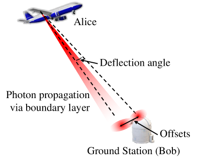
Relevant parameters of aero-optical effects are optical path length (OPL), optical path difference (OPD) and Strehl Ratio (SR), as shown in Figure 1 [45].
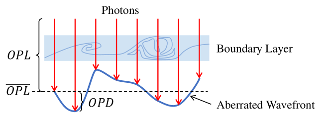
The aero-optical effects are fundamentally caused by the gradient refractive index due to the variable-density flow field, which is expressed by the Gladstone-Dale equation [46]
| (10) |
where is the density of flow field. is the Gladstone-Dale constant decided only the wavelength (µm) of photons [46]
| (11) |
The refractive index field of the airborne boundary layer can be calculated by dividing the density field into sufficiently small squares and performing the Gladstone-Dale equation. The scattered photon path through the boundary layer can be calculated by performing the ray tracing methods [47, 48].
of the photons is calculated by integrating the refractive index along the propagation path [49, 50].
| (12) |
shows the configuration of the wavefront and is defined as
| (13) |
The overline denote the spatial average over the optical aperture. And the phase difference of photons can be defined by
| (14) |
3 Airborne QKD with boundary layer effects
3.1 airborne QKD Scenario
The air-to-ground QKD scenario is shown in Figure 2, the quantum photon source is fixed in the airfoil of the aircraft (Alice) and the QKD receiving module is located at the optical ground station (Bob). Assume that Alice is flying with a constant velocity . The positions of Alice and Bob in East-North-Up (ENU) coordinate system are and . Thus, the distance between Alice and Bob is
| (15) |
The relative flying height can be calculated as
| (16) |
where is the unit vector of Z axis of ENU coordinate system.
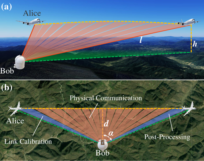
In the top view of airborne QKD scheme (shown in Figure 2(b)), the shortest horizon distance between Alice and Bob can be calculated as
| (17) |
The relative azimuth angle between Alice and Bob can be calculated as
| (18) |
In the airborne QKD scheme, we perform weak-vacuum decoy BB84 protocol with signal photon intensity and decoy photon intensity . The modulating probability of signal (decoy) states is and . The airborne QKD scheme mainly includes three procedures: link calibration, physical communication and post-processing procedure. Once the quantum communication link is established between Alice and Bob after the link calibration procedure, modulated photons are transmitted from Alice to Bob during the physical communication procedure and then post-processing procedure is performed to distill the final secure keys.
3.2 Airborne QKD performance evaluation
The performance evaluation procedure for airborne QKD scheme is mainly contains three steps: photon scattering evaluation, transmission efficiency calculation and key rate estimation, shown in Figure 3.
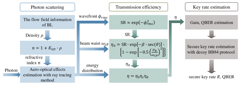
3.2.1 Photon scattering.
Given the aircraft specification, speed , relative flying height and the air density , the density field distribution of the boundary layer can be simulated by the computational fluid dynamics software (such as CFX, Fluent, star-CD and comsol). Afterwards, the refractive index field can be obtained with Gladstone-Dale equation. Thus, when the Gaussian mode beam is propagating through the boundary layer to the ground station, aero-optical effects of photons can be evaluated with the ray tracing method.
The normalized intensity of arrived photons at the ground station can be expressed as
| (19) |
where is the radius of the beam, is the propagated distance of the photons.
is the effective beam waist of the downlink photon at the ground station [51]
| (20) |
where is the pointing error of the transmitter telescope.
is the beam waist at the ground station prior to pointing errors
| (21) |
where is the fried parameter in zenith [51], is zenith angle of the receiving telescope and is the diameter of the transmitter telescope. is the waist radius of transmitted Gaussian beam
| (22) |
where 0.316 results from the fact any aperture passed by real beam results in an Airy disk pattern [51].
3.2.2 Transmission efficiency.
When the beam propagates through the boundary layer and illuminates the receiving telescope, the transmission efficiency can be calculated as [51]
| (23) |
where is the diameter of the receiving telescope, and is the extinction optical thickness between sea level and altitude. The Strehl ratio () is the on-axis beam intensity at the target (far field receiver), , divided by the intensity for a perfect on-axis intensity, , at the target, with the approximation [52]
| (24) |
With the perfect air condition and low flight speed (usually Ma), airborne QKD will be performed without boundary layer effects, which results .
3.2.3 Secure key rate estimation.
In the airborne QKD system, the photon transmission efficiency will be decreased, with the aero-optical effects of the aircraft boundary layer, which can be calculated as
| (25) |
where is the system receiving efficiency caused by constant optical components and is the detector efficiency.
Thus, the decreased overall gain and the increased overall QBER can be calculated by equation (3) and (5). Also, and of single photon counts can be estimated by equation (6) and (7). Afterwards, the secure key rate can be obtained by equation (1).
| Payload | Parameter | Description | Value | ||
|---|---|---|---|---|---|
| Flight speed | 0.7 Ma | ||||
| Relative flying height | 10 km | ||||
| Air density | 0.413 kg/m3 | ||||
| Aircraft |
|
10 km | |||
| Diameter of the transmitter telescope | 0.05 m | ||||
| Transmitter pointing precision [23] | 150 µrad | ||||
| Transmitter wavelength | 1550 nm | ||||
| Waist radius | 0.0158 m | ||||
| Photon Source | Fried parameter in zenith [51] | 0.2 m | |||
| Diameter of the receiver telescope | 0.3 m | ||||
| System detection error rate | 1% | ||||
| Dark count rate | |||||
| Detector efficiency | 15% | ||||
| Ground station | Receiving optical module efficiency | 60% | |||
| Intensity of signal states | 0.8 | ||||
| Intensity of decoy states | 0.1 | ||||
| System repetition rate | 100 MHz | ||||
| Probability of signal states | 50% | ||||
| Probability of decoy states | 25% | ||||
| Protocols | Probability of vacuum states | 25% |
4 Performance analysis
In previous airborne QKD implementations, the quantum photon source payload is usually mounted in the belly pod of aircraft, where the airflow turbulence of boundary layer is much heavier than the airfoil. In this article, we mount the quantum photon source in the airfoil, as slight aero-optical effects to be tolerated and lots of standard models are specified.
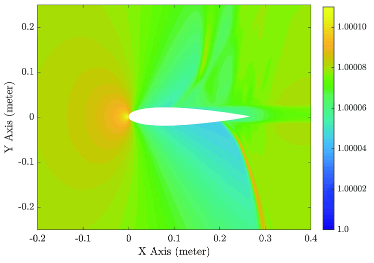
The specific parameters of the aircraft, quantum photon source payload, and optical ground station are shown in Table 1. Here, the standard “NACA0015” airfoil is chosen for the performance analysis of our specified airborne QKD system.
Given the detailed aircraft description with , the boundary layer will be generated around the NACA0015 airfoil and its density field distribution can be simulated by the computational fluid dynamics software (CFX). Afterwards, the refractive index distribution can be calculated by equation (10), shown in Figure 4.
In the air-to-ground QKD scenario, the photon propagated via the boundary layer would be deflected with a certain angle, as shown in Figure 5. With the settings in Table 1, the evaluated deflection angle and the drifted offset of the beam, which reached to the ground station, are shown in Figure 6.
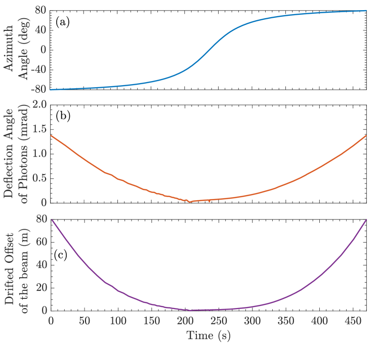
The deflection angle caused by the boundary layer can be up to , and the correspondingly drifted offset of the beam at the ground station is about . Therefore, pre-compensation strategies of the deflection angle, have to be performed to the acquisition, tracking, and pointing (ATP) module of the aircraft quantum photon source payload, with the evaluation of the aero-optical effects caused by the boundary layer. Meanwhile, the ATP performance can be further improved with extra beacon laser module.
The random wavefront aberration of the photons, which are propagated through the boundary layer, is a huge challenge to the airborne QKD system. In Figure 7, we show the energy distribution of photons received by the ground station with different azimuth angles by estimating the and .
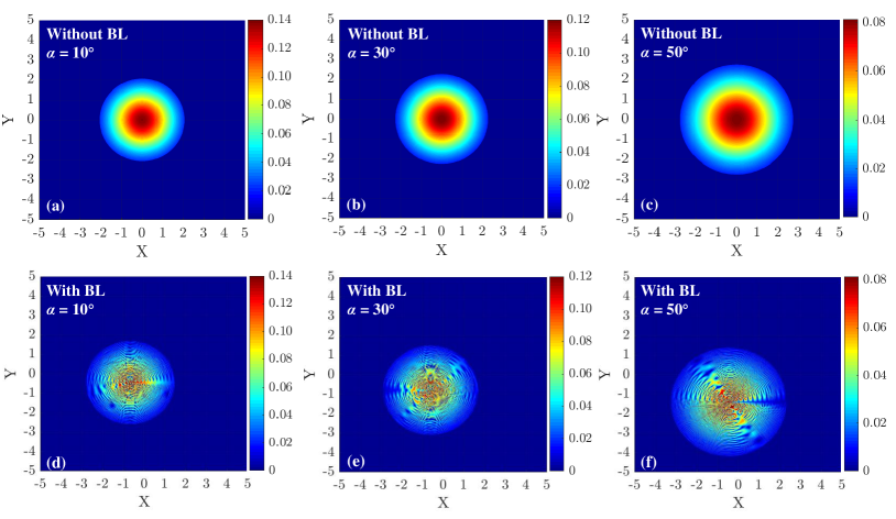
As shown in Figure 7, the wavefront aberration and the diffusion of the beam are much heavier with larger azimuth angle. Meanwhile, the wavefront aberration caused by the boundary layer is complicated and harder to predict in the realistic airborne QKD scenario. Thus, the beacon laser module on the aircraft and the adaptive optics (AO) module on the ground station are suggested to be employed. Therefore, the wavefront aberration of quantum signals can be compensated by adjusting the AO module, based on the analyzed results of the beacon beam wavefront.
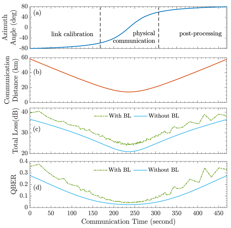
Finally, the performance of the whole airborne QKD session is evaluated and the result is shown in Figure 8. The total communication time is around and the communication distance between the aircraft and the ground station is around to . The boundary layer around aircraft will introduce around channel loss to the transmitted photons, as shown in Figure 8(c). Once the azimuth angle , the estimated QBER of signal states will be larger than , which would result in no secure keys, as shown in Figure 8(d). Thus, we perform the link calibration procedure with azimuth angle and the post-processing procedure with , shown in Figure 8(a). Therefore, the total quantum communication time is around and the communication distance is around to , the estimated final secure key rate is around . If there’s no boundary layer surrounds the aircraft, the estimated secure key rate would be around . In summary, the boundary layer effects can not be ignored in the airborne QKD scenario and heavily decreases the final secure key rate.
5 Conclusion
Airborne quantum key distribution (QKD) will be a flexible bond between terrestrial fiber QKD network and the quantum satellites, which can establish a mobile, on-demand and real-time coverage quantum network. However, the randomly distributed boundary layer is always surrounded to the surface of the aircraft, which would introduce random wavefront aberration, jitter and extra intensity attenuation to the transmitted photons between the aircraft and the ground station. In this article, we propose the detailed performance evaluation scheme of airborne QKD with boundary layer effects. The analyzed photon deflection and wavefront aberration results show that the aero-optical effects caused by the boundary layer can not be ignored, which would heavily decrease the final secure key rate. In our proposed airborne QKD scenario, the boundary layer would introduce loss to the transmitted photons and decrease of the secure key rate. With tolerated quantum bit error rate set to , the suggested quantum communication azimuth angle between the aircraft and the ground station is within . Furthermore, the optimal beacon laser module and adaptive optics module are suggested to be employed to improve the performance of airborne QKD system. Our detailed airborne QKD evaluation study can be performed to the future airborne quantum communication designs.
Appendix
Funding
This work is supported by the National Natural Science Foundation of China under Grant No.61971436, No.61972410 and No.61803382, the Natural Science Basic Research Plan in Shaanxi Province of China (No.2018020JQ6020), the Research Plan of National University of Defense Technology under Grant No.ZK19-13 and No.19-QNCXJ-107, the Postgraduate Scientific Research Innovation Project of Hunan Province under Grant (No.CX20200003).
Availability of data and materials
Simulations and scripts are made available upon request by the corresponding author BL.
Competing interests
The authors declare that they have no competing interests.
Authors’ contributions
The model design and simulations were done by HCY and BYT and BL. The background was analysed by HC and YX. JT and WRY handled the verification of manuscript. The effort was conceived and supervised by BL and co-supervised by LS. HCY and BL wrote the draft and all authors reviewed the manuscript..
References
- [1] Arbekov, I.M., Molotkov, S.N.: Secret keys agreement in communication networks with quantum key distribution and trusted nodes. Laser Physics Letters 17(5), 055202 (2020). doi:10.1088/1612-202x/ab77ce
- [2] Erven, C., Heim, B., Meyer-Scott, E., Bourgoin, J.P., Laflamme, R., Weihs, G., Jennewein, T.: Studying free-space transmission statistics and improving free-space quantum key distribution in the turbulent atmosphere. New Journal of Physics 14(12), 123018 (2012). doi:10.1088/1367-2630/14/12/123018
- [3] Kaur, E., Wilde, M.M., Winter, A.: Fundamental limits on key rates in device-independent quantum key distribution. New Journal of Physics 22(2), 023039 (2020). doi:10.1088/1367-2630/ab6eaa
- [4] Lütkenhaus, N., Shields, A.J.: Focus on quantum cryptography: Theory and practice. New Journal of Physics 11(4), 045005 (2009). doi:10.1088/1367-2630/11/4/045005
- [5] Stucki, D., Legré, M., Buntschu, F., Clausen, B., Felber, N., Gisin, N., Henzen, L., Junod, P., Litzistorf, G., Monbaron, P., Monat, L., Page, J.B., Perroud, D., Ribordy, G., Rochas, A., Robyr, S., Tavares, J., Thew, R., Trinkler, P., Ventura, S., Voirol, R., Walenta, N., Zbinden, H.: Long-term performance of the swissquantum quantum key distribution network in a field environment. New Journal of Physics 13(12), 123001 (2011). doi:10.1088/1367-2630/13/12/123001
- [6] Bennett, C.H., Brassard, G.: Quantum cryptography: Public key distribution and coin tossing. Theoretical Computer Science 560, 7–11 (2014). doi:10.1016/j.tcs.2014.05.025
- [7] Chen, H., Wang, J., Tang, B., Li, Z., Liu, B., Sun, S.: Field demonstration of time-bin reference-frame-independent quantum key distribution via an intracity free-space link. Optics Letters 45(11), 3022–3025 (2020). doi:10.1364/OL.392742
- [8] Xue, Y., Shi, L., Chen, W., Yin, Z., Fan-Yuan, G.-j., Fu, H., Lu, Q., Wei, J.: Improving the performance of reference-frame-independent quantum key distribution through a turbulent atmosphere. Physical Review A 102(6), 062602 (2020). doi:10.1103/PhysRevA.102.062602
- [9] Chen, W., Han, Z., Zhang, T., Wen, H., Yin, Z., Xu, F., Wu, Q., Liu, Y., Zhang, Y., Mo, X., Gui, Y., Wei, G., Guo, G.: Field experiment on a “star type” metropolitan quantum key distribution network. IEEE Photonics Technology Letters 21(9), 575–577 (2009). doi:10.1109/LPT.2009.2015058
- [10] Wang, S., Chen, W., Yin, Z.-Q., He, D.-Y., Hui, C., Hao, P.-L., Fan-Yuan, G.-J., Wang, C., Zhang, L.-J., Kuang, J., Liu, S.-F., Zhou, Z., Wang, Y.-G., Guo, G.-C., Han, Z.-F.: Practical gigahertz quantum key distribution robust against channel disturbance. Optics Letters 43(9), 2030–2033 (2018). doi:10.1364/OL.43.002030
- [11] Wang, X.-B., Yu, Z.-W., Hu, X.-L.: Twin-field quantum key distribution with large misalignment error. Physical Review A 98(6), 062323 (2018). doi:10.1103/PhysRevA.98.062323
- [12] Kozlowski, W., Wehner, S.: Towards Large-Scale Quantum Networks. Association for Computing Machinery, New York, NY, USA (2019). doi:10.1145/3345312.3345497. https://doi.org/10.1145/3345312.3345497
- [13] Hughes, R.J., Nordholt, J.E.: Quantum space race heats up. Nature Photonics 11(8), 456–458 (2017). doi:10.1038/nphoton.2017.124
- [14] Hughes, R.J., Nordholt, J.E., Derkacs, D., Peterson, C.G.: Practical free-space quantum key distribution over 10 km in daylight and at night. New Journal of Physics 4, 43–43 (2002). doi:10.1088/1367-2630/4/1/343
- [15] Bedington, R., Arrazola, J.M., Ling, A.: Progress in satellite quantum key distribution. npj Quantum Information 3(1), 30 (2017). doi:10.1038/s41534-017-0031-5
- [16] Liao, S.-K., Cai, W.-Q., Handsteiner, J., Liu, B., Yin, J., Zhang, L., Rauch, D., Fink, M., Ren, J.-G., Liu, W.-Y., Li, Y., Shen, Q., Cao, Y., Li, F.-Z., Wang, J.-F., Huang, Y.-M., Deng, L., Xi, T., Ma, L., Hu, T., Li, L., Liu, N.-L., Koidl, F., Wang, P., Chen, Y.-A., Wang, X.-B., Steindorfer, M., Kirchner, G., Lu, C.-Y., Shu, R., Ursin, R., Scheidl, T., Peng, C.-Z., Wang, J.-Y., Zeilinger, A., Pan, J.-W.: Satellite-relayed intercontinental quantum network. Physical Review Letters 120(3), 030501 (2018). doi:10.1103/PhysRevLett.120.030501
- [17] Schmitt-Manderbach, T., Weier, H., Fürst, M., Ursin, R., Tiefenbacher, F., Scheidl, T., Perdigues, J., Sodnik, Z., Kurtsiefer, C., Rarity, J.G., Zeilinger, A., Weinfurter, H.: Experimental demonstration of free-space decoy-state quantum key distribution over 144 km. Physical Review Letters 98(1), 010504 (2007). doi:10.1103/PhysRevLett.98.010504
- [18] Vallone, G., Bacco, D., Dequal, D., Gaiarin, S., Luceri, V., Bianco, G., Villoresi, P.: Experimental satellite quantum communications. Physical Review Letters 115(4), 040502 (2015). doi:10.1103/PhysRevLett.115.040502
- [19] Yin, H.-L., Chen, T.-Y., Yu, Z.-W., Liu, H., You, L.-X., Zhou, Y.-H., Chen, S.-J., Mao, Y., Huang, M.-Q., Zhang, W.-J., Chen, H., Li, M.J., Nolan, D., Zhou, F., Jiang, X., Wang, Z., Zhang, Q., Wang, X.-B., Pan, J.-W.: Measurement-device-independent quantum key distribution over a 404 km optical fiber. Physical Review Letters 117(19), 190501 (2016). doi:10.1103/PhysRevLett.117.190501
- [20] Calderaro, L., Agnesi, C., Dequal, D., Vedovato, F., Schiavon, M., Santamato, A., Luceri, V., Bianco, G., Vallone, G., Villoresi, P.: Towards quantum communication from global navigation satellite system. Quantum Science and Technology 4(1), 015012 (2018). doi:10.1088/2058-9565/aaefd4
- [21] Liao, S.-K., Cai, W.-Q., Handsteiner, J., Liu, B., Yin, J., Zhang, L., Rauch, D., Fink, M., Ren, J.-G., Liu, W.-Y., Li, Y., Shen, Q., Cao, Y., Li, F.-Z., Wang, J.-F., Huang, Y.-M., Deng, L., Xi, T., Ma, L., Hu, T., Li, L., Liu, N.-L., Koidl, F., Wang, P., Chen, Y.-A., Wang, X.-B., Steindorfer, M., Kirchner, G., Lu, C.-Y., Shu, R., Ursin, R., Scheidl, T., Peng, C.-Z., Wang, J.-Y., Zeilinger, A., Pan, J.-W.: Satellite-relayed intercontinental quantum network. Physical Review Letters 120(3), 030501 (2018). doi:10.1103/PhysRevLett.120.030501
- [22] Chen, Y.-A., Zhang, Q., Chen, T.-Y., Cai, W.-Q., Liao, S.-K., Zhang, J., Chen, K., Yin, J., Ren, J.-G., Chen, Z., Han, S.-L., Yu, Q., Liang, K., Zhou, F., Yuan, X., Zhao, M.-S., Wang, T.-Y., Jiang, X., Zhang, L., Liu, W.-Y., Li, Y., Shen, Q., Cao, Y., Lu, C.-Y., Shu, R., Wang, J.-Y., Li, L., Liu, N.-L., Xu, F., Wang, X.-B., Peng, C.-Z., Pan, J.-W.: An integrated space-to-ground quantum communication network over 4,600 kilometres. Nature 589(7841), 214–219 (2021). doi:10.1038/s41586-020-03093-8
- [23] Nauerth, S., Moll, F., Rau, M., Fuchs, C., Horwath, J., Frick, S., Weinfurter, H.: Air-to-ground quantum communication. Nature Photonics 7(5), 382–386 (2013). doi:10.1038/nphoton.2013.46
- [24] Liu, H.-Y., Tian, X.-H., Gu, C., Fan, P., Ni, X., Yang, R., Zhang, J.-N., Hu, M., Guo, J., Cao, X., Hu, X., Zhao, G., Lu, Y.-Q., Gong, Y.-X., Xie, Z., Zhu, S.-N.: Optical-relayed entanglement distribution using drones as mobile nodes. Physical Review Letters 126(2), 020503 (2021). doi:10.1103/PhysRevLett.126.020503
- [25] Pugh, C.J., Kaiser, S., Bourgoin, J.-P., Jin, J., Sultana, N., Agne, S., Anisimova, E., Makarov, V., Choi, E., Higgins, B.L., Jennewein, T.: Airborne demonstration of a quantum key distribution receiver payload. Quantum Science and Technology 2(2), 024009 (2017). doi:10.1088/2058-9565/aa701f
- [26] DeCesare, A., Snyder, R., Carvalho, D., Miller, W., Alsing, P., Ahn, D.: Toward Mobile Free-space Optical QKD: Characterization of a Polarization-based Receiver. SPIE Defense + Commercial Sensing, vol. 11391. SPIE, Online Only (2020). https://doi.org/10.1117/12.2567295
- [27] Liu, H., Tian, X.-H., Gu, C., Fan, P., Ni, X., Yang, R., Zhang, J.-N., Hu, M., Guo, J., Cao, X., hu, X., Zhao, G., Lu, Y.-Q., Gong, Y.-X., Xie, Z., Zhu, S.-N.: Drone-based entanglement distribution towards mobile quantum networks. National Science Review 7, 921–928 (2020). doi:10.1093/nsr/nwz227
- [28] Zhang, M., Zhang, L., Wu, J., Yang, S., Wan, X., He, Z., Jia, J., Citrin, D.S., Wang, J.: Detection and compensation of basis deviation in satellite-to-ground quantum communications. Optics Express 22(8), 9871–9886 (2014). doi:10.1364/OE.22.009871
- [29] Moll, F., Botter, T., Marquardt, C., Pusey, D., Shrestha, A., Reeves, A., Jaksch, K., Gunthner, K., Bayraktar, O., Mueller-Hirschkorn, C., Gallardo, A.D., Diaz Gonzalez, D., Rosenfeld, W., Freiwang, P., Leuchs, G., Weinfurter, H.: Stratospheric QKD: Feasibility Analysis and Free-space Optics System Concept. SPIE Security + Defence, vol. 11167. SPIE, Strasbourg, France (2019). https://doi.org/10.1117/12.2539076
- [30] Yan, X., Zhang, P.-F., Zhang, J.-H., Qiao, C.-H., Fan, C.-Y.: Quantum polarization fluctuations of partially coherent dark hollow beams in non-kolmogorov turbulence atmosphere. Chinese Physics B 25(8), 084204 (2016). doi:10.1088/1674-1056/25/8/084204
- [31] Bonato, C., Aspelmeyer, M., Jennewein, T., Pernechele, C., Villoresi, P., Zeilinger, A.: Influence of satellite motion on polarization qubits in a space-earth quantum communication link. Optics Express 14(21), 10050–10059 (2006). doi:10.1364/OE.14.010050
- [32] Du, X., Zhao, D., Korotkova, O.: Changes in the statistical properties of stochastic anisotropic electromagnetic beams on propagation in the turbulent atmosphere. Optics Express 15(25), 16909–16915 (2007). doi:10.1364/OE.15.016909
- [33] Toyoshima, M., Takenaka, H., Takayama, Y.: Atmospheric turbulence-induced fading channel model for space-to-ground laser communications links. Optics Express 19(17), 15965–15975 (2011). doi:10.1364/OE.19.015965
- [34] Tyler, G.A., Boyd, R.W.: Influence of atmospheric turbulence on the propagation of quantum states of light carrying orbital angular momentum. Optics Letters 34(2), 142–144 (2009). doi:10.1364/OL.34.000142
- [35] Anufriev, A.V., Zimin, Y.A., Vol’pov, A.L., Matveev, I.N.: Change in the polarization of light in a turbulent atmosphere. Soviet Journal of Quantum Electronics 13(12), 1627–1628 (1983). doi:10.1070/qe1983v013n12abeh005021
- [36] Shan, X., Sun, X., Luo, J., Tan, Z., Zhan, M.: Free-space quantum key distribution with rb vapor filters. Applied Physics Letters 89, 191121 (2006)
- [37] Yin, J., Ren, J.-G., Lu, H., Cao, Y., Yong, H.-L., Wu, Y.-P., Liu, C., Liao, S.-K., Zhou, F., Jiang, Y., Cai, X.-D., Xu, P., Pan, G.-S., Jia, J.-J., Huang, Y.-M., Yin, H., Wang, J.-Y., Chen, Y.-A., Peng, C.-Z., Pan, J.-W.: Quantum teleportation and entanglement distribution over 100-kilometre free-space channels. Nature 488(7410), 185–188 (2012). doi:10.1038/nature11332
- [38] Liao, S.-K., Yong, H.-L., Liu, C., Shentu, G.-L., Li, D.-D., Lin, J., Dai, H., Zhao, S.-Q., Li, B., Guan, J.-Y., Chen, W., Gong, Y.-H., Li, Y., Lin, Z.-H., Pan, G.-S., Pelc, J.S., Fejer, M.M., Zhang, W.-Z., Liu, W.-Y., Yin, J., Ren, J.-G., Wang, X.-B., Zhang, Q., Peng, C.-Z., Pan, J.-W.: Long-distance free-space quantum key distribution in daylight towards inter-satellite communication. Nature Photonics 11(8), 509–513 (2017). doi:10.1038/nphoton.2017.116
- [39] Buttler, W.T., Hughes, R.J., Lamoreaux, S.K., Morgan, G.L., Nordholt, J.E., Peterson, C.G.: Daylight quantum key distribution over 1.6 km. Physical Review Letters 84(24), 5652–5655 (2000). doi:10.1103/PhysRevLett.84.5652
- [40] Moll, F., Nauerth, S., Fuchs, C., Horwath, J., Rau, M., Weinfurter, H.: Communication System Technology for Demonstration of BB84 Quantum Key Distribution in Optical Aircraft Downlinks. SPIE Optical Engineering + Applications, vol. 8517. SPIE, San Diego, California, United States (2012). https://doi.org/10.1117/12.929739
- [41] Vallone, G., Dequal, D., Tomasin, M., Vedovato, F., Schiavon, M., Luceri, V., Bianco, G., Villoresi, P.: Interference at the single photon level along satellite-ground channels. Physical Review Letters 116(25), 253601 (2016). doi:10.1103/PhysRevLett.116.253601
- [42] Gordeyev, S., Smith, A.E., Cress, J.A., Jumper, E.J.: Experimental studies of aero-optical properties of subsonic turbulent boundary layers. Journal of Fluid Mechanics 740, 214 (2014)
- [43] Gordeyev, S., Rennie, M.R., Cain, A.B., Hayden, T.: Aero-optical measurements of high-mach supersonic boundary layers. In: 46th AIAA Plasmadynamics and Lasers Conference, p. 3246 (2015)
- [44] Ma, X., Qi, B., Zhao, Y., Lo, H.-K.: Practical decoy state for quantum key distribution. Physical Review A 72(1), 012326 (2005). doi:10.1103/PhysRevA.72.012326
- [45] Sun, X.-w., Yang, X.-L., Liu, W.: Aero-optical suppression for supersonic turbulent boundary layer. Journal of Turbulence 22(1), 1–25 (2021). doi:10.1080/14685248.2020.1849709
- [46] Merzkirch, W.: 3 - Optical Flow Visualization, pp. 115–231. Academic Press, San Diego (1987). doi:10.1016/B978-0-08-050658-6.50007-2. https://www.sciencedirect.com/science/article/pii/B9780080506586500072
- [47] Jones, M., Bender, E.: CFD-based computer simulation of optical turbulence through aircraft flowfields and wakes. Fluid Dynamics and Co-located Conferences, pp. 2001–2798. American Institute of Aeronautics and Astronautics, Anaheim,CA,U.S.A. (2001). doi:10.2514/6.2001-2798 10.2514/6.2001-2798. https://doi.org/10.2514/6.2001-2798
- [48] Guo, G., Liu, H., Zhang, B.: Aero-optical effects of an optical seeker with a supersonic jet for hypersonic vehicles in near space. Applied Optics 55(17), 4741–4751 (2016). doi:10.1364/AO.55.004741
- [49] Ding, H., Yi, S., Zhao, X., Yi, J., He, L.: Research on aero-optical prediction of supersonic turbulent boundary layer based on aero-optical linking equation. Optics Express 26(24), 31317–31332 (2018). doi:10.1364/OE.26.031317
- [50] Ding, H., Yi, S., Zhu, Y., He, L.: Experimental investigation on aero-optics of supersonic turbulent boundary layers. Applied Optics 56(27), 7604–7610 (2017). doi:10.1364/AO.56.007604
- [51] Neumann, S.P., Joshi, S.K., Fink, M., Scheidl, T., Blach, R., Scharlemann, C., Abouagaga, S., Bambery, D., Kerstel, E., Barthelemy, M., Ursin, R.: Q3sat: quantum communications uplink to a 3u cubesat—feasibility & design. EPJ Quantum Technology 5(1), 4 (2018). doi:10.1140/epjqt/s40507-018-0068-1
- [52] Ross, T.S.: Limitations and applicability of the maréchal approximation. Applied Optics 48(10), 1812–1818 (2009). doi:10.1364/AO.48.001812