(Preprint) Seirios: Leveraging Multiple Channels for LoRaWAN Indoor and Outdoor Localization
Abstract.
Localization is important for a large number of Internet of Things (IoT) endpoint devices connected by LoRaWAN. Due to the bandwidth limitations of LoRaWAN, existing localization methods without specialized hardware (e.g., GPS) produce poor performance. To increase the localization accuracy, we propose a super-resolution localization method, called Seirios, which features a novel algorithm to synchronize multiple non-overlapped communication channels by exploiting the unique features of the radio physical layer to increase the overall bandwidth. By exploiting both the original and the conjugate of the physical layer, Seirios can resolve the direct path from multiple reflectors in both indoor and outdoor environments. We design a Seirios prototype and evaluate its performance in an outdoor area of 100 m 60 m, and an indoor area of 25 m 15 m, which shows that Seirios can achieve a median error of 4.4 m outdoors (80% samples ¡ 6.4 m), and 2.4 m indoors (80% samples ¡ 6.1 m), respectively. The results show that Seirios produces 42% less localization error than the baseline approach. Our evaluation also shows that, different to previous studies in Wi-Fi localization systems that have wider bandwidth, time-of-fight (ToF) estimation is less effective for LoRaWAN localization systems with narrowband radio signals.
1. Introduction
LoRa is an emerging technology that provides wide-range wireless network coverage for low power embedded Internet of Things (IoT) devices (Chiani and Elzanaty, 2019; Liando et al., 2019; LoRa Alliance, 2017; Zhang et al., 2020; Xie and Xiong, 2020). LoRaWAN, a MAC-layer protocol based on LoRa, is widely used to provide reliable and secure wireless communication (Adelantado et al., 2017; de Carvalho Silva et al., 2017; Dongare et al., 2018; LoRa Alliance, 2017). As millions of IoT devices are deployed with valuable assets both indoors and outdoors (Liando et al., 2019; Peng et al., 2018; Talla et al., 2017; Xu et al., 2019), localization becomes an important service that can enable a wide range of location-based applications. GPS is a popular technology for acquiring such location information outdoors. However, it requires specialized hardware (i.e., GPS receiver) with additional cost, and it does not work indoors.
An alternative is to exploit common localization algorithms with existing infrastructure (i.e., gateways) of LoRaWAN, such as received signal strength (RSS)-based location fingerprinting, and time difference of arrival (TDoA)-based or angle of arrival (AoA)-based triangulation, to locate embedded IoT devices; this requires no extra hardware (e.g., a GPS module) and may work indoors (Islam et al., 2019; Iliev and Paprotny, 2015). However, one major disadvantage of these approaches is their undesirable localization accuracy. Taking LoRaWAN as an example, according to one LoRaWAN geolocation whitepaper,111 Hyperlink will be revealed in the final version. RSS-based localization can only provide 1,000-2,000 m accuracy. While TDoA-based localization algorithms claim to provide 20-200 m accuracy, an outdoor evaluation in a public LoRaWAN shows that such algorithms achieved a median accuracy of 200 m only (Podevijn et al., 2018). Such poor localization accuracy cannot meet the requirements of many applications such as geofencing and asset tracking.
A major performance bottleneck of radio-based localization is the radio multipath effect. Previous research shows that both RSS- and TDoA-based localization methods suffer from significant errors due to the multipath effect (Gu et al., 2018; Chintalapudi et al., 2010; Wang et al., 2017). Recently, researchers have proposed many approaches to improve the localization accuracy for LoRa (Chen et al., 2019; Gu et al., 2018; Wolf et al., 2018; Nandakumar et al., 2018). However, those approaches require either extra hardware (e.g., drones) or modification of the end nodes. Conversely, super-resolution algorithms (Kotaru et al., 2015; Li et al., 2016; Soltanaghaei et al., 2018; Vasisht et al., 2016; Xie et al., 2019; Xiong and Jamieson, 2013, 2015; Joshi et al., 2015; Kotaru and Katti, 2018; Wang et al., 2016; Ma et al., 2019) that have been well investigated to resolve the multipath effect and improve the accuracy of Wi-Fi-based localization have not yet been studied for LoRaWAN. This inspired us to study super-resolution algorithms with an existing LoRaWAN infrastructure for better localization performance.
Super-resolution algorithms extract the significant reflectors (though strongly coherent) from incoherent channel state measurements and resolve the direct path. Incoherent channel state measurements can be obtained with antenna arrays (Xiong and Jamieson, 2013) or multiple sub-carriers in wideband signals (Kotaru et al., 2015). Kotaru et al. propose SpotFi to utilize multiple subcarriers as virtual sensors with only three physical antennas, which can reduce the cost of large antenna arrays but provide accurate localization with Wi-Fi signals. However, the LoRaWAN narrowband signal has only one carrier, and the radio signals in different communication channels are naturally out of sync, making it difficult to utilize multiple carriers as virtual antennas. Chronos (Vasisht et al., 2016) proposes synchronizing multiple Wi-Fi channels through two-way channel state information (CSI) measurements and packet exchange. However, this approach is difficult to apply in LoRaWAN since its data rates can be very slow (e.g., 300 bps), making two-way CSI communication costly; to the best of our knowledge, embedded LoRaWAN radio transceivers cannot measure CSI. ToneTrack (Xiong and Jamieson, 2015) proposes utilizing the phase slope of the CSIs of the subcarriers to synchronize overlapped wideband Wi-Fi channels. However, LoRaWAN channels are not overlapped, and the phase slope of a narrowband is not as clear as a wideband such as Wi-Fi. This makes it difficult to synchronize LoRaWAN non-overlapped narrowband channels using this method directly. Further, even considering all eight channels (a LoRaWAN device can support up to eight channels with frequency hopping), with the time-of-flight (ToF) estimation method in SpotFi, the overall 1.6 MHz LoRaWAN bandwidth still has a poor resolution of 625 , equating to 125 m of radio propagation and making it challenging to resolve multipaths in clutter environments.
In summary, the two main challenges for LoRaWAN localization using super-resolution algorithms are:
-
•
the unsynchronized channel state measurements in different non-overlapped communication channels
-
•
insufficient resolution for solving multipath with super resolution algorithms.
To this end, we propose Seirios,222Seirios (Sirius) is the ancient Greek god or goddess of the Dog Star, which is the brightest star in the night sky and an important reference for celestial navigation around the Pacific Ocean. which exploits the CSI of multiple channels as incoherent measurements and utilizes super-resolution algorithms on multiple anchors (i.e. gateways) to provide accurate localization for LoRaWAN devices both indoors and outdoors. It works with legacy LoRaWAN devices, and the gateways or access points (APs) can be acquired with off-the-shelf hardware, making it cost-effective to deploy.
Seirios exploits the unique structure of the radio signals (i.e., linear chirps that sweep the whole band; see Sec. 3.1 for details) to synchronize them in multiple non-overlapped LoRaWAN channels without two-way communications. In addition to the channel state measurements themselves, Seirios utilizes the conjugate of the measurements, which doubles the total amount of information, for better multipath resolution. The contributions of this paper are as follows.
-
•
We propose a novel interchannel synchronization algorithm to obtain the synchronized CSI of non-overlapped multiple channels by exploiting the unique structure of the LoRaWAN physical layer. Compared to prior work (Vasisht et al., 2016), our approach does not require two-way communications in CSI measurements, which is more applicable to LoRaWAN architecture.
-
•
We propose doubling the amount of channel information by utilizing both the original and the conjugate of the CSI to increase the numbers of multipaths that the super-resolution algorithms can resolve (up to six reflectors for our prototype AP implementation with two antennas), thus improving the accuracy of localization.
-
•
We design and implement a prototype of Seirios with software-defined radios (SDRs) as the APs and off-the-shelf embedded LoRaWAN devices. Our evaluation in a 100 m 60 m outdoor area and a 25 m 15 m indoor area shows that Seirios achieves a median localization error of 4.4 m and 2.4 m respectively, which are approximately two times smaller than the baseline approaches. Different to observations in previous studies with Wi-Fi localization systems, our results show that ToF estimation is less effective for narrowband LoRaWAN localization.
2. Related Work
2.1. LoRa Localization
Localization systems with, for instance, Wi-Fi, Bluetooth Low Energy (BLE) and cellular network etc. have achieved sub-meter level accuracy as shown in Table 1. However, those technologies cannot provide lower power and long range communications for IoT applications. With the rapidly increasing popularity of LPWAN technologies for lower power and long range communications and the importance of localization, recent research has attempted to address the challenges and error sources based on LPWAN infrastructure to improve localization accuracy (Li et al., 2020). Rajalakshmi et al. propose a multi-band backscatter system for localization with subcentimeter-sized devices (Nandakumar et al., 2018), which is, however, not compatible with legacy devices. Chen et al. propose an amplitude-based anti-multipath method using a LoRaWAN radio signal that achieves 4.6 m accuracy indoors (Chen et al., 2019). However, this approach requires specially designed antennas as opposed to the common omnidirectional antennas. Besides, mounting a LoRaWAN receiver in a flying drone to collect the radio signal from a transmitter at multiple locations is not suitable for conventional stationary LoRaWAN gateway deployment. To this end, we propose Seirios to exploit the existing infrastructure to locate the legacy devices with stationary gateways.
| Research | Technology | Low Power | Range | Accuracy |
|---|---|---|---|---|
| (Xiong and Jamieson, 2015; Kotaru et al., 2015; Soltanaghaei et al., 2018; Vasisht et al., 2016) | Wi-Fi | - | 12-25 m | ¡0.9 m |
| (Hou and Arslan, 2017; Lazik et al., 2015; Bargh and de Groote, 2008) | Bluetooth | ✓ | 10 m | 1 m |
| (Kumar et al., 2014; Sun et al., 2005) | Cellular | ✗ | 35-60 m | 0.85 m |
| (Vasisht et al., 2018; Nandakumar et al., 2018; Ma et al., 2017) | Backscatter | ✓ | ¡10 m | ¡0.5m |
| (Aernouts et al., 2020; Podevijn et al., 2018) | LPWAN | ✓ | 500 m+ | ¿100 m |
| OwLL (Bansal et al., 2021) | LPWAN | ✓ | 500 m+ | 9 m |
| Seirios (outdoor) | LPWAN | ✓ | 100 m | 5 m |
| WideSee (Chen et al., 2019) | LPWAN | ✓ | 40 m | 4.6 m |
| Seirios (indoor) | LPWAN | ✓ | 25 m | 2.4 m |
2.2. Channel Combination
Increasing the bandwidth is a useful approach to increase the localization accuracy. Xiong et al. propose ToneTrack (Xiong and Jamieson, 2015) to utilize a channel-combining algorithm to increase the bandwidth for finer radio multipath resolution. However, this approach is for overlapped wideband (Wi-Fi) signals only. Nevertheless, it inspired us to combine non-overlapped narrowband LoRaWAN signals to increase the bandwidth for localization (Sec. 4.3). As the resolution of the combined bandwidth signal is still poor (i.e., 125 m), it cannot be used in localization directly. Bansal et al. propose OwLL (Bansal et al., 2021) to exploit TV whitespace band (up to hundreds of MHz) to increase the accuracy of LoRaWAN localization. There are two major differences between OwLL and Seirios. First, OwLL sends hundreds of packets to cover up to tens or hundreds of MHz whitespace radio frequencies, while Seirios uses LoRaWAN bandwidth (i.e., 1.6 MHz with eight channels) only. Thus, there are energy consumption implications of transmitting such a large number (e.g., 80 to 120 packets) of packets for localization. In comparison, Seirios transmits eight packets only, which is a fraction, i.e., 1/15 to 1/10, as that of OwLL. For limited bandwidth (e.g., 1.6 MHz) scenarios, we will argue that ToF related algorithms are in fact less effective in Sec. 4.4 for LoRaWAN localization, and thus Seirios is based AoA only. Second, for synchronization, OwLL follows Chime (Gadre et al., 2020) to use an extra transmitter to synchronize the phase of multiple base stations (i.e. gateways), while Seirios exploits the microstructure of chirps to synchronize the phases of the LoRa packets in multiple channels instead of synchronizing base stations. Please see Table. 2 for the detailed comparison between OwLL and Seirios.
| Features | OwLL (Bansal et al., 2021) | Seirios | ||
|---|---|---|---|---|
| Bandwidth | 400 MHz | 1.6 MHz | ||
| Localization time | 20.97s | 0.24s | ||
| Localization technique | TDoA | AoA | ||
| Packets per localization | 80-120 | 8 | ||
|
1-1.8 years | 10+ years | ||
| Synchronization | Base stations | Multiple channels | ||
| Range | 500 m | 100 m | ||
| Accuracy | m | m (outdoors) |
2.3. Virtual Antennas
Kotaru et al. propose SpotFi to create a virtual sensor array with the number of elements greater than the number of multipaths, thus, overcoming the constraint posed by a limited number of antennas (Kotaru et al., 2015). That said, the model proposed in SpotFi is designed for ToF-AoA joint estimation with MUSIC, which produces poor accuracy for LoRaWAN. Therefore, we propose a novel model for accurate AoA estimation with ESPRIT to avoid the unreliable ToF estimation. Moreover, we propose utilizing the conjugates of the channel measurements to further increase the number of virtual antennas, which can further improve localization accuracy.
2.4. Spatial Smoothing
Spatial smoothing scheme is proposed by Evan et al. to solve coherent signal classification (Evans, 1981). ArrayTrack (Xiong and Jamieson, 2013) is a uniform linear array (ULA) with eight antennas that utilizes spatial smoothing by averaging two adjacent antennas to resolve multipaths to improve the accuracy of AoA estimation. Theoretical studies by Pillai et al. (Pillai and Kwon, 1989) and Pan et al. (Pan et al., 2020) show that using both forward and conjugated backward spatial smoothing can further improve the number of coherent signals that can be resolved. However, this method does not work for ULAs with a small number of antennas (e.g., two or three) only, which are available in low-cost hardware. To this end, SpotFi (Kotaru et al., 2015) proposes using a special Wi-Fi signal model with multiple channels for spatial smoothing with three antennas. We note that SpotFi does not make use of the conjugate information due to a significantly larger number of communication channels available in Wi-Fi (e.g., 30 against eight in LoRaWAN). Therefore, the bandwidth constraint problem is unique to LoRa signal studied in this paper. Seirios is inspired by both SpotFi and conjugated backward techniques to propose a novel LoRa signal model, which solves coherent multipath signals with a small number of antennas (i.e., two) and a limited number of channels (i.e., eight).
Summary:
Seirios is inspired by the channel combination technique of ToneTrack, the virtual antenna model of SpotFi and conjugated backward spatial smoothing. First, it features a channel combination method for non-overlapped narrowband signals to increase the overall bandwidth. Second, instead of using the MUSIC model in SpotFi, Seirios utilizes a novel model with virtual antennas to accurately estimate AoA with the ESPRIT algorithm to avoid unreliable ToF estimation. Moreover, it exploits the conjugates of the measurements to further increase the number of virtual antennas and the capacities for multipath resolution.
3. Background
3.1. LoRa Premier
| Symbol | Definition |
|---|---|
| SF | LoRa spreading factor |
| BW | LoRa bandwidth |
| Sampling rate | |
| LoRa symbol duration | |
| Number of channels | |
| Number of multipaths | |
| Channel response | |
| Covariance matrix | |
| Steering matrix | |
| CSI matrix | |
| Diagonal matrix of the angle of arrival | |
| Matrix of path attenuation | |
| Chirp rate in linear chirps | |
| Speed of light | |
| Sensor spacing (i.e., distance between two antennas) | |
| Carrier frequency | |
| Channel spacing (i.e., frequency between two channel) |
Before discussing LoRa, note Table 3, which summarizes the mathematical symbols used in the following sections. LoRa is modulated with a chirp spread spectrum (CSS) (Chiani and Elzanaty, 2019; Adelantado et al., 2017). This is configured by the spreading factor () and bandwidth (). is defined as an integer from 7 to 12, representing the number of encoded bits per chirp symbol, and is the bandwidth of a channel, typically 125 kHz or 500 kHz (LoRa Alliance, 2017). An up-chirp has its frequency increasing linearly, while a down-chirp is the opposite. A chirp is the minimum unit of a LoRa radio signal, and a LoRa packet is modulated as the concatenation of different chirps. The structure of a LoRa packet can be found in Fig. 1.
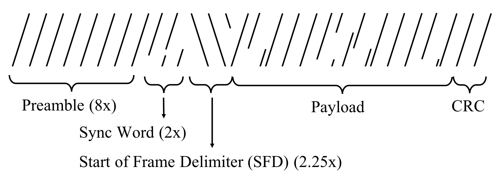
Note: The x-axis reflects time, and the y-axis reflects frequency
The preambles are identical to facilitate the packet detection. Preambles consist of a predefined number (e.g., eight for LoRaWAN) of up-chirps, and the frequency of an up-chirp is defined as
| (1) |
where is the chirp rate, and is the duration of the chirp. The phase of up-chirp can be obtained by integrating as,
| (2) |
Then, an up-chirp with normalized magnitude can be represented as,
| (3) |
3.2. Signal Model
Suppose there are significant paths between a sender and a receiver. Since the signal is narrowband, the channel response of each path can be modeled as a complex value , representing the amplitude attenuation and phase shift compared to the original signal that has been sent. The received signal is the sum of multipath replicas of the original signal as
| (4) |
where is the ToF of the -th path. With a Fourier transform, we can transfer Eq (4) into the frequency domain as,
| (5) |
where is the frequency. Therefore, we can obtain the channel response by
| (6) |
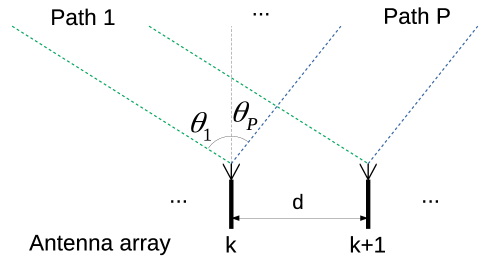
Suppose we have equally spaced channels with frequency spacing and antennas. We use the central frequency to represent the frequency of the whole narrowband channel and to represent the channel response of the -th () channel measured by the -th () antenna. Each path has an AoA , as depicted in Fig. 2. Therefore, can be represented by
| (7) |
where is the antenna spacing—that is, the distance between the adjacent antennas ( and )—and is the speed of light. For simplicity, we use or to represent the phase shift caused by the AoA and or caused by the ToF . We have
| (8) | ||||
| (9) | ||||
| (10) | ||||
| (11) |
For linear chirps, as suggested by Eq. (1), frequency increases linearly and monotonically with time. With Eq. (6), the channel response for continuous frequency can be measured with linear chirps. For example, 125 kHz LoRa chirp with central frequency 920 MHz can be used to measure the channel response from 919.9375 MHz to 920.0625 MHz. Seirios utilizes this microstructure of LoRa signals to obtain the channel response of continuous frequency and perform interchannel synchronization (see Sec. 4.3 for details).
3.3. MUSIC and ESPRIT
MUSIC (Schmidt, 1986; Kotaru et al., 2015; Li et al., 2016) and ESPRIT (Roy et al., 1986; Roy and Kailath, 1989) are two popular super-resolution algorithms, and have been shown to resolve the multipath effect in wideband radio (e.g., Wi-Fi) localization systems.
Previous research has shown that increasing the number of antennas (e.g., up to eight) can improve the localization accuracy (Xiong and Jamieson, 2013) at the cost of extra hardware (antenna). To this end, Seirios can operate with two antennas, which is cost-effective. For a pair of antennas ( and ) with LoRaWAN channels, the measurements matrix for MUSIC can be organized as:
| (12) |
The steering vector required by MUSIC is
| (13) |
We can then utilize the classical MUSIC algorithm with and to estimate each radio signal path between a sender and a receiver by searching the AoA and ToF that can generate peaks on the MUSIC pseudo-spectrum.
Alternatively, we can also use ESPRIT to solve multipaths. The measurement matrices and for antenna and can be organized as
| (14) | ||||
| (15) |
We can compose a model for ESPRIT as
| (16) |
where , , is the noise, and is a steering matrix. By solving with ESPRIT, the AoAs are estimated.
We skip the details of MUSIC and ESPRIT for brevity.
4. Design
As discussed in Sec. 1, Seirios utilizes triangulation with multiple APs. The key to improving localization accuracy is to improve AoA estimation. In this section, we will focus on interchannel synchronization (Sec. 4.3) and improved super-resolution algorithms (Sec. 4.5) to overcome the challenges discussed in Sec. 1. This will subsequently improve the accuracy of AoA estimation as well as the performance of the localization system.
4.1. System Design

Seirios is designed to exploit multiple LoRaWAN APs to locate a transmitter. The location and antenna direction of APs are known in advance and stored in the cloud. Here, the APs sense the radio signal transmitted from the transmitter before relaying them to the cloud server. We assume that there is only one transmitter and no concurrent transmission at the same channel. Then, the transmitter is located, after which the cloud server synchronizes the channels and performs an AoA estimation from the radio signal measured at each AP. Each AP in Seirios has at least two synchronized antennas. The distance between the two antennas is slightly less than half of the wavelength. If there is one path only between the transmitter and an AP, the AoA can be calculated directly by comparing the phase difference of the received signal between two antennas. However, in reality, there are multiple paths due to radio signal reflection. Even though the line-of-sight (LoS) path exists, other paths may cause significant errors in the AoA estimation due to radio signal self-interference.
Prior studies show that the number of significant reflectors in an indoor environment is 5.05 on average, with a standard deviation of 1.95 (Vasisht et al., 2016). For an outdoor or uncluttered indoor environment, there will be even fewer significant reflectors (e.g., four). Therefore, one of the research questions concerns how to accurately estimate the AoA of a limited number of paths in such environments (both indoor and outdoor) with narrowband radio signals (e.g., LoRaWAN).
Fig. 3 shows an illustrated example where Seirios decomposes the radio wave multipaths generated by the tree reflectors, estimates the AoA of the radio wave in different APs, and locates the target successfully.
4.2. Channel State
Channel state information (CSI) represents how signals at certain carrier frequencies propagate from the transmitter to the receiver along multiple paths (Ma et al., 2019). It has been widely used in Wi-Fi signal based localization systems (Kotaru et al., 2015; Xiong and Jamieson, 2015; Soltanaghaei et al., 2018; Wang et al., 2016; Xie et al., 2019). To measure CSI, a Wi-Fi transmitter sends packets whose preamble contains pre-defined training symbols for each subcarrier. When the training symbols are received, the receiver can measure CSI by comparing the amplitude and phase of the received symbols with the pre-defined training symbols.
For LoRa, similar CSI can be obtained. At the receiver, the radio signal can be sampled as a complex sequence of and components. Seirios detects the preamble and applies the digital processing algorithms introduced in (Ghanaatian et al., 2019) for precise carrier frequency offset (CFO) and sampling time offset (STO) calibration. In the following discussion, we assume that all LoRa chirps are well calibrated. Since both the sender and the receiver know the preamble, this can be regarded as a training sequence. Here, LoRa CSI can be obtained by comparing the received preambles with the pre-defined preambles (i.e., linear up-chirps).
Furthermore, we can sum up the repeating up-chirps in the preamble to improve the signal-to-noise ratio (SNR) in CSI estimation. There are two factors ensuring that the up-chirps can be summed up as follows. Firstly, since the frequency modulation for up-chirp is symmetric (see Eq. (1)), the phase will roll back to its initial state after the period of one chirp, and, thus, all these up-chirps have the same phase. Moreover, the preamble only lasts for a small amount of time and the channel response does not change during this period. Thus, all these up-chirps have the same CSI. Therefore, we can combine all the up-chirps by
| (17) |
where stands for the number of up-chirps in the preamble, is the -th up-chirp received, and represents the summation of received up-chirps.
To this end, LoRa CSI can be measured by,
| (18) |
where is the zero-phased up-chirp defined in Eq. (3), and denotes the conjugate transpose. Eq. (18) is similar to the pulse compression technique, which is used in LoRa demodulation to significantly increase the SNR.
Different to Chronos (Vasisht et al., 2016), which estimates the CSI of a wireless link by comparing the CSI measurements in the two end nodes of the link, Seirios estimates the CSI by comparing the received up-chirps in the preamble with the reference on the receivers only. The advantage of our approach is two-fold. First, none of the embedded LoRaWAN devices (transmitters) is capable of measuring CSI. Seirios requires CSI measurements in one end (i.e., LoRaWAN gateway) only, while Chronos requires both ends to measure CSI. This makes Seirios cost-effective to deploy because the number of embedded devices is orders of magnitude more than that of gateways. Second, the data rates of LoRaWAN (can be as low as 300 bps) are orders of magnitude smaller than those of Wi-Fi (the lowest is 1 Mbps). Therefore, transmitting the CSI measurements between two ends incurs significantly more time and (energy) costs in LoRaWAN.
We have discussed the method for LoRa CSI measurements above. Below, we will discuss how CSI can be used in localization.
Recall that both MUSIC and ESPRIT utilize channel response to resolve radio signal multipaths (see Sec. 3.2 and Sec. 3.3). The main difference between CSI and channel response is a random phase shift that is introduced in CSI because the transmitter and the receiver are not synchronized. For wideband Wi-Fi signals, CSIs for each subcarrier are measured at the same time. The phase shift is the same for each subcarrier, so it does not affect the results of super-resolution algorithms. Therefore, CSI can be used directly by the super-resolution algorithms.
However, for the -th narrowband channel of LoRa measured by antenna , is phase-shifted from (see Eq. (7)) as
| (19) |
where and are the initial phases of the transmitter and the receiver, respectively. Since a LoRa channel (here LoRa channels may be viewed as the Wi-Fi subcarriers) is measured individually, the random phase shift is different in each channel. Therefore, unlike Wi-Fi CSI, LoRa CSI must be calibrated before it can be used by the super-resolution algorithms.
Calibrating the phase shift is equivalent to synchronizing the LoRa channels by solving in Eq. (19). However, solving the synchronization problem between a transmitter and a receiver is challenging. Chronos (Vasisht et al., 2016) proposed measuring CSI on both the transmitter and the receiver to eliminate the phase shift, yet the method requires extra hardware to measure CSI in embedded LoRaWAN transmitters, which is undesirable.
Conversely, in the context of localization, we do not need to estimate the absolute values of the phase shifts. Instead, we need an identical phase shift—say, the phase shift of the first channel—for all calibrated channels to be used by the super-resolution algorithms. In the next section, we will discuss how to exploit the microstructure of LoRa signal for synchronization.
4.3. Interchannel Synchronization


First of all, let us briefly review the related work discussed in Sec. 2.2. ToneTrack (Xiong and Jamieson, 2015) has proposed a method to align overlapped Wi-Fi channels. (Adjacent channels are regarded as the special forms of the overlapped channels in this paper, to be differentiated from non-overlapped channels.) It first equalizes the phase slope in the frequency domain; then, it aligns the phase of the last subcarrier of the first wideband channel and the first subcarrier of the second wideband channel. With these two steps, the second wideband channel can be concatenated to the first channel to form a wider band. However, this method only works for overlapped channels. By contrast, Seirios improves the method to operate on non-overlapped narrowband channels.
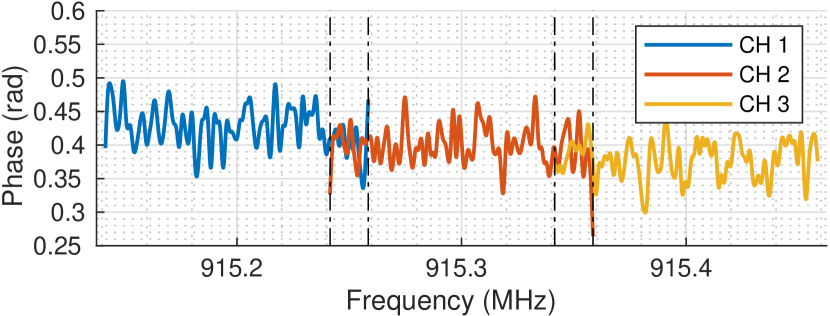
Different to a Wi-Fi signal, which has multiple subcarriers to form a phase slope, a narrowband LoRaWAN signal has only one carrier. To form a similar phase slope for the LoRaWAN signal, we exploit the microstructure of LoRa chirps. For illustration, we define as the channel state for a continuous frequency range from the lower bound to the upper bound of the bandwidth. Fig. 4(a) shows an example of the phase slopes for three channels (915.2 MHz, 915.3 MHz, and 915.4 MHz). Note the random phase shift in between is caused by lack of synchronization (see the discussion in Sec. 4.2). Eq. (1) shows that frequency and time have a linear relationship. Therefore, we can estimate for channel as
| (20) |
where , is the carrier frequency of channel . Fig. 4(a) depicts the phase of for .
However, unlike the stable phase slope illustrated by (Xiong and Jamieson, 2015), the phase slope of the LoRa narrowband channel is full of noise even when the SNR is high (see Fig. 4(b), where the SNR is 10 dB). This is because that the phase change in a narrowband (e.g., in channel 1 the phase decreases by approximately 0.05 rad, as shown in Fig. 4(b)) is much less than that of a Wi-Fi wideband (e.g., approximately 3.0 rad in (Xiong and Jamieson, 2015)), and, thus, the narrowband is less robust to the noise than Wi-Fi even with the same noise level. To better estimate the phase offset between two channels, Seirios averages the phase offset within the overlapped frequency to reduce the noise. By compensating the phase offset of the second channel to align with the first channel, the second channel can now be concatenated to the end of the first channel, as shown in Fig. 4(b).
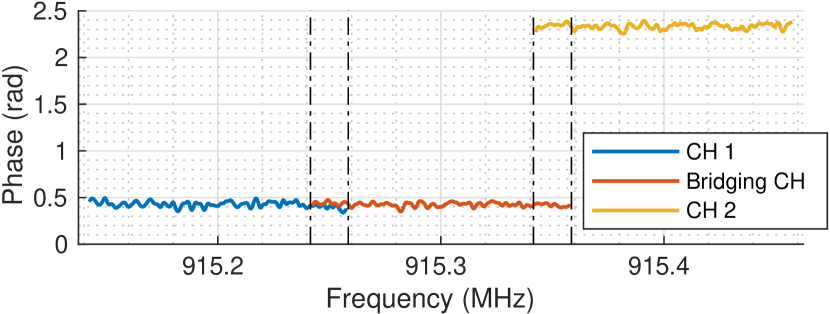
For non-overlapped channels, ToneTrack states that estimating the correct amount of phase offset is challenging. To this end, for narrowband radio signals, we propose to generate a (virtual) intermediate channel response as a bridge to assist the synchronization. In the microbenchmark in Sec. 6, we show that channel response varies slowly with frequency, making it possible to generate the virtual intermediate channel with small errors by averaging the two adjacent channels. Taking Fig. 4(c) as an example, we can obtain the (virtual) intermediate channel response (shown as a bridging channel in the figure) by averaging the phases of (co-phased) channel 1 and channel 2. Similar to the overlapped channels, non-overlapped channels can now be synchronized with the (virtual) intermediate channel (Fig. 4(d)).
Unlike Wi-Fi wideband, which measures multiple CSIs in one packet, a LoRa narrowband can only measure one CSI per packet. To measure the CSI of multiple channels, at least one packet on each channel should be transmitted within the coherence time. A LoRaWAN end device has eight channels of 125 kHz with 200 kHz spacing. Eight packets should be transmitted on eight different channels to measure their CSI. LoRaWAN channels are separated by 75 kHz guard bands, and the (virtual) intermediate channel has a 25 kHz overlap with the adjacent channels. In practice, Seirios leaves out the first and the last 4 kHz because the quality of phase estimation in transient is poor. Thus, the overlapped frequency of one LoRaWAN channel (with the virtual bridging channel) is 17 kHz (13.6% of the bandwidth), which is sufficient for synchronization (see our evaluation in Sec. 6.2 for more details). The synchronized CSI can later be used in super-resolution algorithms for multipath resolution.
4.4. Limitation of ToF Estimation
A typical configuration of LoRaWAN has 8 125 kHz channels with the channel spacing of 200 kHz between two adjacent channels. Therefore, we can measure the CSI for each channel with a pair of antennas and (see Sec. 4.2) as
| (21) |
Following the spatial smoothing approach used in (Kotaru et al., 2015) to maximize the incoherence of measurements for better multipath resolution, the measurement matrix for MUSIC is
| (22) |
We can obtain a steering vector according to Eq. (13) with . With and the steering vector , we can use MUSIC to estimate AoA and ToF jointly. The super-resolution algorithm searches all combinations of and for the steering vector and calculates the value of a pseudo-spectrum function to find the peaks where the most likely estimations are located. However, as shown in our evaluation in Sec. 7, the localization performance is poor and sometimes even worse than the baseline. Thus, we observe the following:
-
•
ToF resolution is 625 (125 m), making the paths with ToF difference indistinguishable. In the pseudo-spectrum, those estimations merge into one peak which is away from the ground truth. Therefore, the attempt to resolve multipaths fails. With a wider bandwidth (e.g., 20 MHz as Wi-Fi), accuracy can be improved.
-
•
AoA estimation is sensitive to ToF accuracy. If ToF is estimated poorly, it will be noisy for AoA estimation, making AoA estimation worse than the baseline.
Therefore, we look for other algorithms that can avoid using ToF estimation for direct path resolution.
4.5. AoA Estimation with Conjugate
ESPRIT (Roy et al., 1986; Roy and Kailath, 1989; Hu et al., 2014) takes advantage of rotational invariance for AoA estimation. However, it is not used widely in Wi-Fi super-resolution-based localization schemes due to its inferior performance compared to MUSIC (Oumar et al., 2012). One possible reason for this is that ESPRIT does not estimate ToF as MUSIC does. Since LoRa has orders of magnitude less bandwidth than Wi-Fi (see Sec 4.1), ToF estimation is inaccurate and will reduce the overall performance. With ESPRIT, we can exploit all the information for AoA estimation only, which may have better performance than AoA-ToF joint estimation. Our results in Secs. 6 and 7 show that AoA estimation alone has better performance than AoA-ToF joint estimation.
The signal model for ESPRIT is shown as Eq. (16). Measurements are organized in two matrices, and . (We abuse the notations as those in Sec. 4.4 for brevity.) A naïve approach is to follow Eq. (14) and (15) for a pair of antennas to form matrices with 8 1 dimensions. However, their covariance matrix is rank deficient with rank one, which indicates that the number of multipaths the algorithm can solve is one only.
As discussed in Sec. 2.4, spatial smoothing can resolve multipath. However, when averaging subsets of antennas, it also reduces the number of effective antennas. For example, the number of effective antennas in ArrayTrack is reduced from eight to seven after averaging two adjacent antennas (Xiong and Jamieson, 2013). With two antennas in Seirios, there will be only one effective antenna left after spatial smoothing, which can only solve one path. Therefore, we cannot use the spatial smoothing proposed in (Xiong and Jamieson, 2013) directly. Instead, Seirios follows the technique proposed in SpotFi (Kotaru et al., 2015) to do spatial smoothing with a special signal model to increase the rank to four. Our evaluation shows that solving four paths is useful for outdoor localization, but results in poor accuracy for indoor localization. To improve the localization performance in multipath-rich environments, the rank should be further increased.
Pillai et al. (Pillai and Kwon, 1989) show that conjugated backward spatial smoothing can further improve the number of coherent signals that it can resolve for ULA from 333 stands for the integer part of to ( stands for the number of antennas). For Seirios, and , which means that this technique cannot improve multipath resolution if it is applied directly. However, it shows that the conjugates have extra information and can be utilized in spatial smoothing to further improve multipath resolution. Therefore, we extend the aforementioned signal model to include the conjugates of the measurements to solve more multipaths.
To this end, we propose to exploit both the original and the conjugate of the measurements. We call this algorithm conjugated ESPRIT. and can be organized with CSIs from Eq. (21)
| (23) |
as a 6 6 matrix, and symmetrically,
| (24) |
With Eq. (16)(23)(24), we know that is a 6 6 steering matrix, and we can derive to show that the decomposition of and exists. Mathematically, we have , and
| (25) | ||||
| (26) |
The rows of represent multipath signals. Normally, multipath signals (defined in Eq. (10)) are highly correlated. With Eq. (25) and (26), the signals are no longer correlated. As shown in Eq. (23) and (24), the number of the measurements is doubled from that without conjugates. Therefore, the rank of covariance matrix is increased from four to six to resolve more possible multipaths. Generally, given the measurements of channels, the multipaths that conjugated ESPRIT can solve is . Our evaluation shows that the proposed algorithm can increase the accuracy of LoRaWAN indoor localization.
4.6. Multiple AP fusion


Previous research proposes determining the direct path based on ToFs (Kotaru et al., 2015; Xiong and Jamieson, 2015; Vasisht et al., 2016). Similarly, by using AoA-ToF joint estimation (Sec. 4.4), we can determine the direct path and apply triangulation for localization. However, the results of AoA-ToF joint estimation are not reliable, as discussed in Sec. 4.4. Evaluation also suggests that AoA-ToF joint estimation has poor performance in localization (see Sec. 7). Alternatively, Seirios can exploit the conjugated ESPRIT for reliable AoA estimation (Sec. 4.5). However, the algorithm proposes all the possible directions of incoming paths regardless of direct paths or reflectors, making it difficult to determine the direct path with one AP only. Therefore, Seirios does not resolve the direct path at the beginning. Instead, Seirios fusions the AoA estimation of multiple APs to locate the transmitter. This method is based on the fact that the origins of the direct paths are congregated at the transmitter, but that of the reflectors are diverged (see examples in Figs. 3 and 6). Different to the classical triangulation algorithm that minimizes the 2-norm of localization errors, Seirios utilizes a maximum likelihood algorithm to simplify the calculation.
Notably, Seirios deals with all estimated AoAs equally, as they can be either the direct paths or the reflectors. The errors of AoA estimation are modeled as Gaussian distributions . Therefore, we can apply a function with the Gaussian distribution’s probability density function (PDF) to represent the likelihood of a correct estimation for any angle . is defined as
| (27) |
where is the AoA estimation of the th path, and is determined by the noise level and is a tunable parameter of Seirios. We found that the “good” values of are between and empirically. Fig. 5 is an example of the likelihood function .
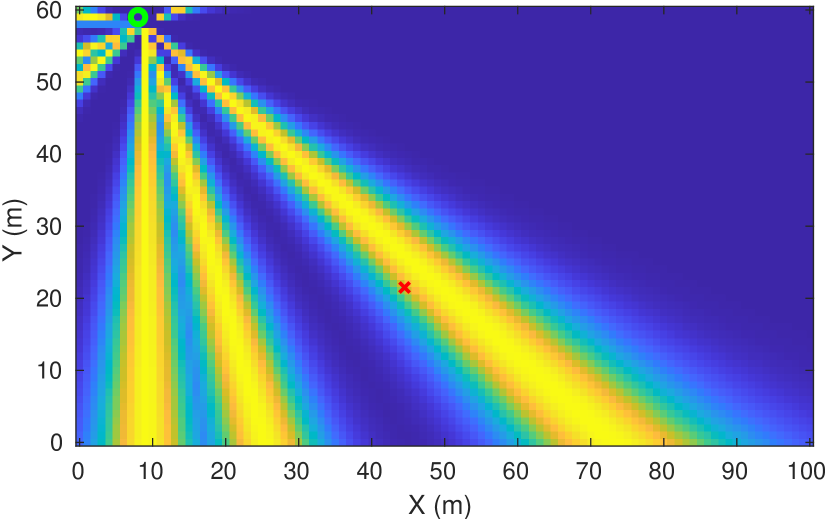
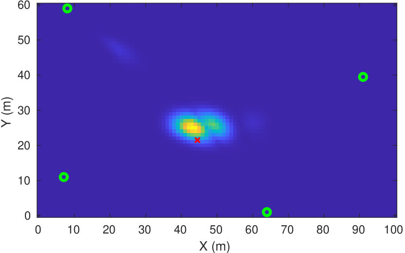
Since the position of APs and the directions of antennas are known, we can translate the likelihood function into a heat map demonstrating the likelihood of the transmitter’s location, as shown in Fig. 6(a). As the size of the antenna array is relatively small compared to the distance between the transmitter and the receiver, instead of using hyperbolas to translate the AoAs into a heat map, we use straight lines to simplify the calculation. To fusion the likelihood estimated by multiple APs, Seirios merges the heat maps through multiplication. Therefore, the hea tmap as the fusion of APs is generated by
| (28) |

CSI: channel state information; PHY: physical layer
However, there might be multiple clusters if the number of APs is insufficient. Increasing the APs can subsequently reduce ambiguity. Fig. 6 shows the refining of location estimation as the number of APs increases. On the heat map with two APs (Fig. 6(b)), there are many possible locations for the transmitter. With four APs (see Fig. 6(d)), the transmitter’s location is estimated as the center of a cluster, which is very close to the ground truth (i.e., the red cross). With the multiple AP fusion algorithm, it is unnecessary to determine the direct path for each AP, which can avoid inaccurate ToF estimation, as discussed in Sec. 4.4.
LoRa signals are good at penetration, hence, why in most of the cases there exist direct paths. The study and evaluation of cases in which direct paths are completely blocked can be addressed in future studies.
5. Implementation
Seirios is designed for transmitter localization in an outdoor or uncluttered indoor environment. According to the architecture shown in Fig. 3, we implemented a Seirios prototype with the APs for wireless data acquisition and the cloud service for data processing.
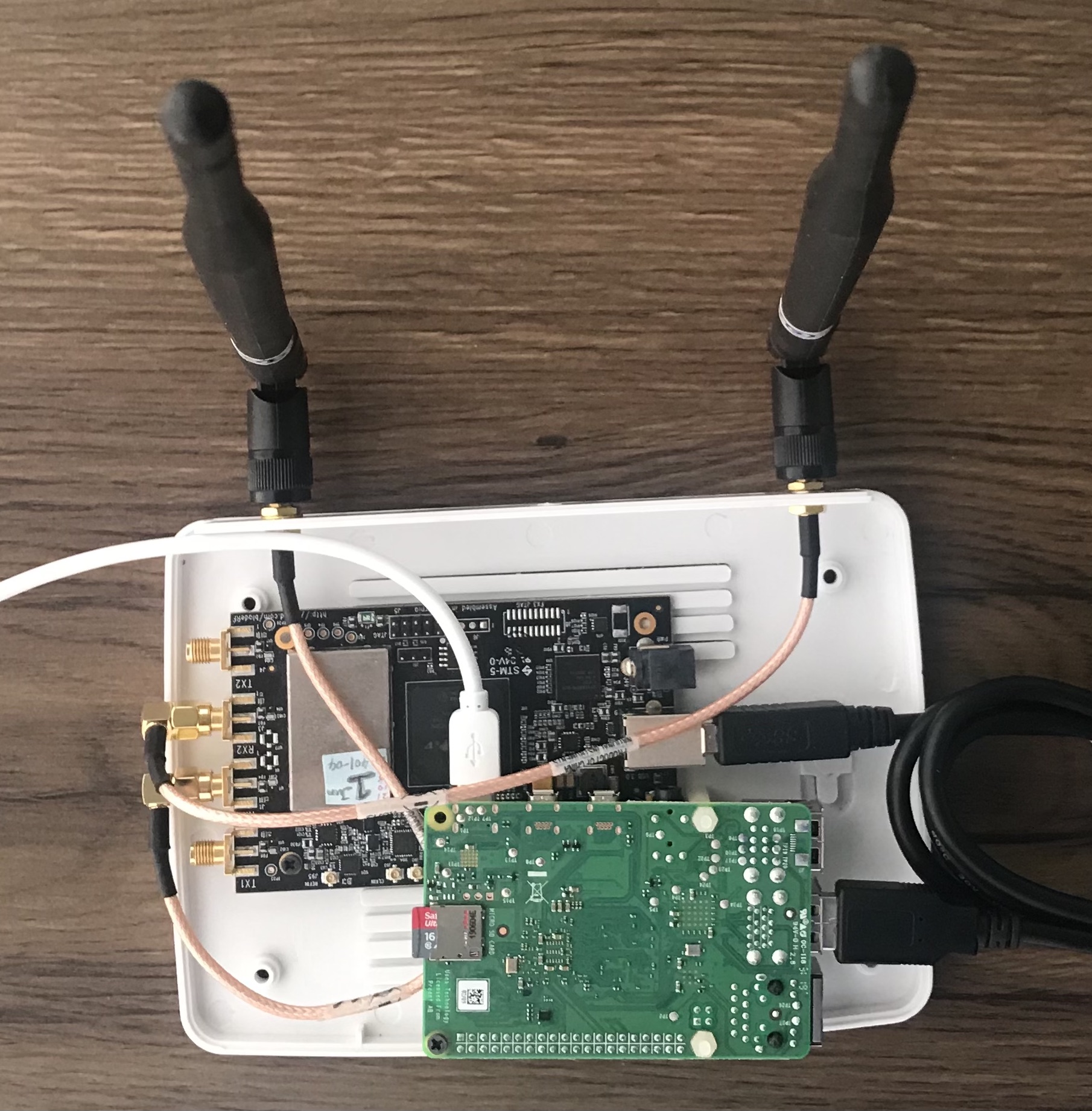
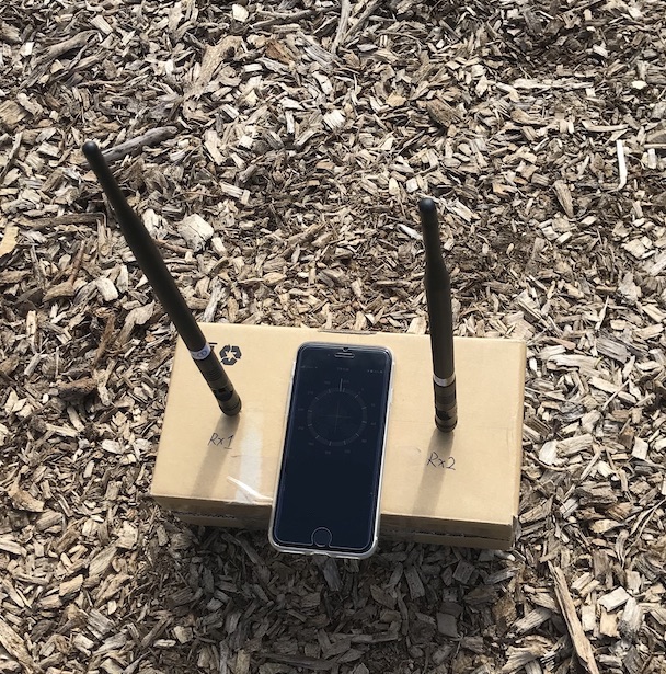
Seirios AP prototype. We used bladeRF 2.0 SDR, which supports 2 2 MIMO as the AP prototype to receive LoRa radio signals between 902 MHz and 928 MHz. The SDR has two antennas (LoRa gateways usually have only two antennas (Xie and Xiong, 2020; Zhang et al., 2020)), and can generate two synchronized and streams with 12-bit resolution. The distance between antennas is fixed at 14cm, which is slightly less than half of the radio wavelength. Prior calibration is performed to eliminate the phase offset caused by connectors or cables. The SDR is connected to a general-purpose processor (GPP) via USB 3.0, which can be either a PC or a single board embedded computer. To operate the Seirios prototype in a mobile manner (e.g., in an outdoor environment), we decided to use a low-power embedded system Raspberry Pi 4 as the GPP, which is deployed with a signal processing program for LoRa packet detection. The signal processing algorithm is implemented in C++ with GNU Radio for high efficiency. Once a LoRa packet is detected, the GPP uploads the packet to the Seirios cloud service prototype using high-speed WiFi. The devices are shown in Fig. 8(a). For outdoor deployment, the devices are packed in a case (see Fig. 8(b)).
Cloud server. The cloud has a TCP server for incoming LoRa PHY that is uploaded by multiple APs. The server stores the data with a timestamp and maintains a time window to group the relevant packets for further processing. For each AP, when at least one packet for each channel is recorded in the window, the server will start to process the data. It first extracts and synchronizes the CSI for each channel. Then, it performs either MUSIC or ESPRIT for the AoA estimation. After that, the server will perform multiple-AP fusion to estimate the location of the transmitter. A flowchart of the process is shown in Fig. 7.
6. Microbenchmark

AoA: angle of arrival; CDF: cumulative distribution function; ToF: time of flight
So far, we have discussed interchannel synchronization (Sec. 4.3) and conjugated ESPRIT (Sec. 4.5) as the key algorithms of Seirios to improve the accuracy of AoA estimation as well as the localization of LoRaWAN IoT devices. To understand the performance of the algorithms on one AP, we conducted a microbenchmark indoors (25 m 15 m) with LoS and non-line of sight (NLoS) to evaluate the AoA estimation accuracy. We compared three algorithms (i.e. AoA-conjugated using conjugated ESPRIT, Sec. 4.5; AoA-ToF joint estimation using MUSIC, Sec. 4.4; and the baseline). The baseline algorithm is similar to TDoA, but instead of synchronizing multiple APs for timestamp measurement, we synchronized two antennas of one AP to extract the time difference based on the phase difference and further calculated AoA based on the measurements.
6.1. AoA Estimation Accuracy
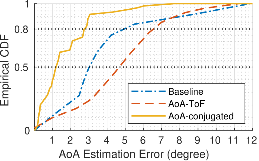
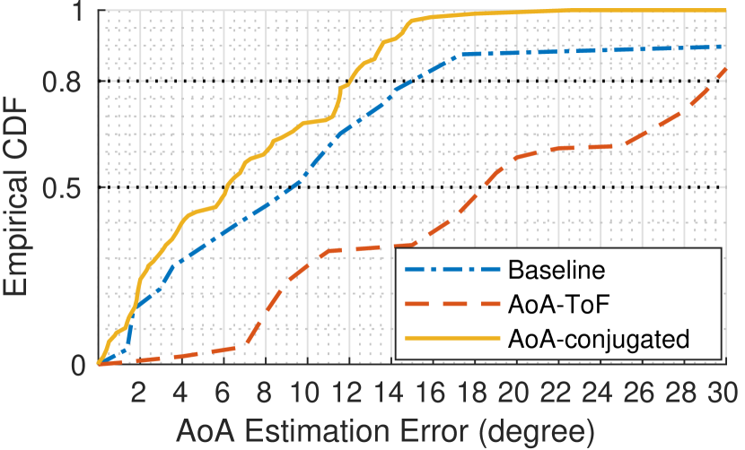
Figs. 9(a) and 9(b) show the cumulative distribution function (CDF) for AoA estimation errors of the AoA-conjugated, AoA-ToF, and the baseline, for LoS and NLoS, respectively. The lab where the data were collected is a typical cluttered indoor environment. For LoS, AoA-conjugated (median error ) has three times superior accuracy compared to AoA-ToF () and 1.5 times compared to the baseline (). Compared to the previous observation in a Wi-Fi localization system, AoA-ToF joint estimation has even worse performance than the baseline (see Sec. 4.4 for an explanation of this result). For NLoS, the radio path is completely blocked by walls so that only penetrated radio (with much noise) can reach the receiver. The median error (, , and for AoA-conjugated, AoA-ToF and the baseline, respectively) is larger than those under LoS, but AoA-conjugated still has the best performance. Therefore, we can conclude that AoA estimation with conjugated ESPRIT can, on average, improve the accuracy by two times compared to the baseline.
6.2. Interchannel Synchronization
If using customized LoRa protocol (Xu et al., 2019) instead of LoRaWAN, one may define overlapped LoRa channels, and exploit them to improve localization accuracy. However, the communication channels defined by LoRaWAN do not overlap (to avoid interchannel interference and improve transmission performance); therefore, a virtual intermediate channel must be synthesized to synchronize LoRaWAN channels, as discussed in Sec. 4.3. Theoretically, synchronization for non-overlapped channels may introduce extra errors compared to overlapped channels, which may increase the AoA estimation and localization errors. In practice, the extra error is relatively small.
For demonstration, we conducted a microbenchmark to compare the performance of Seirios in non-overlapped and overlapped LoRa channels. To have overlapped channels, a LoRa transmitter is programmed to transmit packets in 15 channels of 125 kHz with the channel spacing of 100 kHz, 30 times over. We selected odd numbers of channels (i.e., st, rd, th) from the overlapped dataset to form a “new” dataset of non-overlapped channels.
Then, we performed conjugated ESPRIT on both datasets for AoA estimation. Fig. 9(c) shows that there is insignificant difference between the two datasets (i.e., overlapped and non-overlapped). Taking the median error for comparison, the loss () of the non-overlapped dataset is very small and is only one-eighth of its improvement from the baseline. Therefore, the error introduced by non-overlapped channels has little effect on AoA estimation.
7. Evaluation
7.1. Goals, Metrics and Methodology
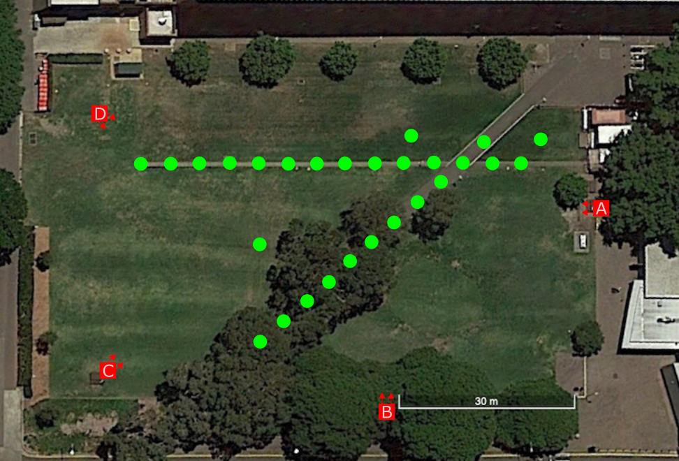
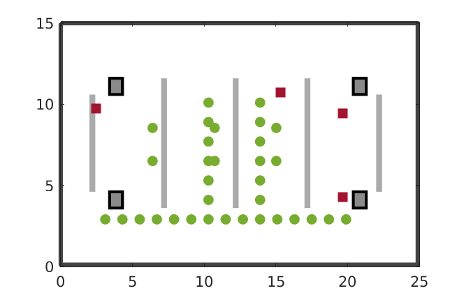
Our goal in this evaluation was to show that Seirios can locate a LoRa transmitter accurately for both outdoor and indoor environments. For this purpose, we evaluated the performance of the Seirios prototype developed in Sec. 5 in a 100 m 60 m lawn with several trees, surrounded by buildings (see Fig. 10), and in a 25 m 15 m large room with concrete pillars, surrounded by walls (see Fig. 11).
For outdoor scenarios, we deployed four APs on the lawn, one of which is shown in Fig. 8(b). A pair of 5 dBi antennas was mounted on each AP. The devices were battery powered and each were sampling at 2 MSps to cover the 1.6 MHz LoRaWAN spectrum. We used mDots444 Hyperlink will be revealed in the final version. as the transmitters (i.e., the embedded LoRaWAN devices to be localized), which were configured with frequency hopping at eight LoRaWAN channels. The APs can overhear the packets sent by the transmitters on each channel and use them for localization. For convenience, the transmitters were configured with burst transmission, and each of them transmitted packets for from channel 0 to channel 7, with the channel spacing of 200 kHz. It took a device approximately 30 ms to send a predefined packet; therefore, it took approximately ms to cover all the channels. The transmit power was fixed as 14 dBm.
During the evaluation, each of the transmitters transmitted LoRaWAN packets in all channels a total of three times. At the same time, we recorded the locations of the transmitters as the ground truth (see the green dots and the red squares in Fig. 10 for the locations of the transmitters and APs, respectively).
Similarly, we deployed APs and transmitters in our lab for indoor evaluation. As mentioned, the lab is a cluttered environment with furniture and walls (see Fig. 11). The transmitters were configured similarly to those for outdoor evaluation.
The metrics used to evaluate the performance of Seirios is the error of localization (in meters), which is simply the absolute distance between the estimation and the ground truth.
Besides overall localization performance with conjugated ESPRIT (Sec. 4.5), AoA-ToF joint estimation (Sec. 4.4), and the baseline (Sec. 6), we also investigated the performance of different components of Seirios such as the fusion algorithm (see Sec. 4.6), and the effectiveness of conjugated ESPRIT.
Note: Values are measured in meters.
7.2. Outdoor Localization
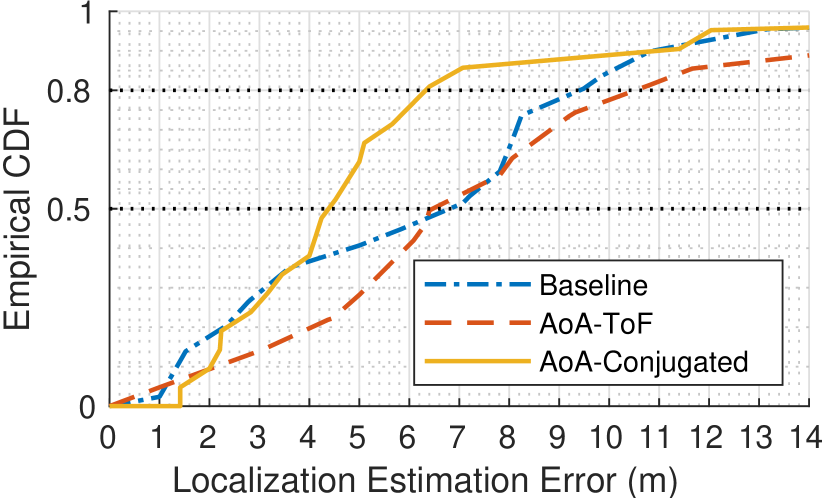

For the outdoor evaluation on the campus lawn shown in Fig. 10, the overall performance of Seirios is shown in Fig. 12(a). The performance of conjugated ESPRIT is better than that of AoA-ToF joint estimation and the baseline with the median localization errors of 4.4 m, 6.4 m, and 6.9 m for conjugated ESPRIT, AoA-ToF joint estimation, and the baseline, respectively. The 80th percentiles are 6.4 m, 10.5 m, and 9.4 m for conjugated ESPRIT, AoA-ToF joint estimation, and the baseline, respectively.
The results show that the localization error is reduced by 36.2% when comparing conjugated ESPRIT with the baseline. Further, conjugated ESPRIT has better performance than AoA-ToF joint estimation, which is different to the results reported in previous Wi-Fi localization literature. This phenomenon is due to the foundation of the model discussed in Sec. 4.4 that an accurate AoA estimation with AoA-ToF joint estimation relies on an accurate ToF estimation, while the ToF estimation is sensitive to the raw resolution limited by the overall bandwidth of LoRaWAN channels that is orders of magnitude smaller than that of Wi-Fi channels. AoA-ToF joint estimation performs worse than the baseline, which shows that the error introduced by an inaccurate ToF estimation reduce the performance of AoA estimation.
The results also indicate that super-resolution algorithms are useful for outdoor environments. Even though the number of multipaths is smaller than that of indoor environments, the strong radio signal reflection can be caused by trees and nearby buildings, which increase localization errors.
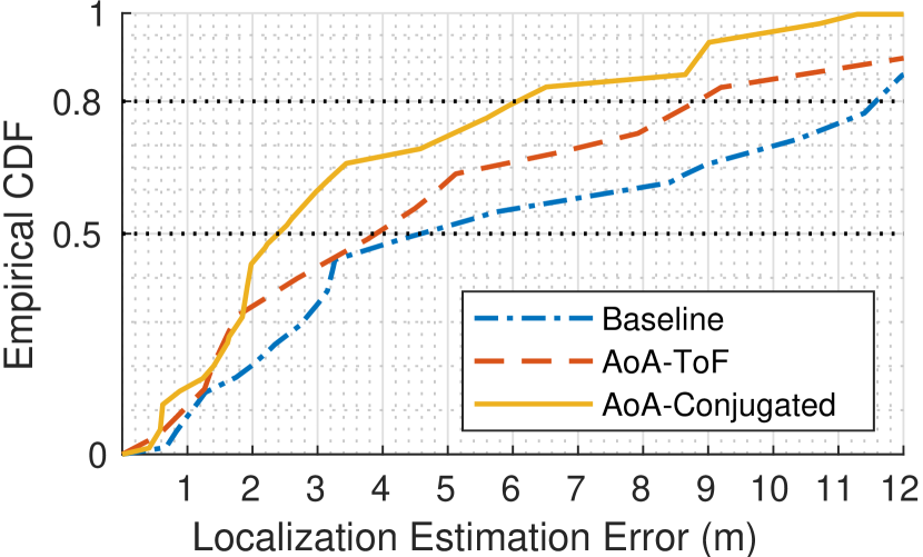
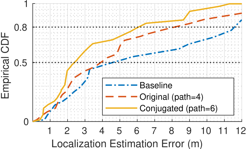
7.3. Indoor Localization
For the indoor evaluation in our lab, as shown in Fig. 11, the overall performance of Seirios is shown in Fig. 12(b). The median errors with conjugated ESPRIT, AoA-ToF joint estimation, and the baseline are 2.4 m, 4.0 m, and 4.6 m, respectively, and the 80th percentiles are 6.1 m, 8.8 m, and 11.6 m, respectively. The results show that with the conjugated ESPRIT, the localization error is reduced by 47.8% compared to the baseline, which is slightly more than that of outdoor evaluation (36.2%, see Sec. 7.2). This is because the multipath effect is more severe indoors than outdoors, which affects the baseline algorithm but can be resolved by the conjugated ESPRIT. On average (indoors and outdoors), the localization improvement is 42%, which demonstrates the superior localization performance of Seirios (i.e., conjugated ESPRIT) on narrow bandwidth radio signals with commercially available off-the-shelf (COTS) hardware, which has two antennas only.
Unlike outdoor evaluation, AoA-ToF joint estimation is better than the baseline indoors. The reason behind this phenomenon is that ToF estimation is apt to average the ToF of multipaths if they are not distinguishable, and indoor paths have relatively similar ToF, so the estimation is relatively more accurate than those of outdoors evaluations (with significantly larger different ToF for each path). The relatively accurate ToF estimation can improve the accuracy of AoA estimation, so that the localization performance of AoA-ToF joint estimation is better than the baseline. Nevertheless, multipaths are not resolvable with AoA-ToF joint estimation, so its performance is worse than that of conjugated ESPRIT.
7.4. Comparison with RSS and TDoA-based Approaches
As discussed in Sec. 1, RSS and TDoA based LoRaWAN localization systems have poor performance. In this section, we evaluate these techniques in both indoor and outdoor environments as a comparison to Seirios. For the RSS-based approach, we follow a general path-loss model proposed in (Liu et al., 2007; Schmid et al., 2010) with triangulation for evaluation. For the TDoA-based approach, we use the phase difference of two synchronized antennas in each gateway to calculate TDoA.
The median outdoor localization errors are 15.3 m and 6.9 m for RSS and TDoA based approaches, respectively, while the median indoor localization errors are 6.3 m and 4.6 m for RSS and TDoA based approaches, respectively. Therefore, the AoA-based conjugated ESPRIT of Seirios produces significantly better performance (4.4 m outdoors, 2.4 m indoors) than these of RSS and TDoA based approaches.
7.5. Impact of AP Fusion
AoA estimation proposes the possible directions of all incoming paths regardless of the direct path or reflectors. AP fusion is an effective technique to determine the direct path as well as the location of the transmitter. It is based on the fact that the direct paths are congregated but the reflectors are diverged.
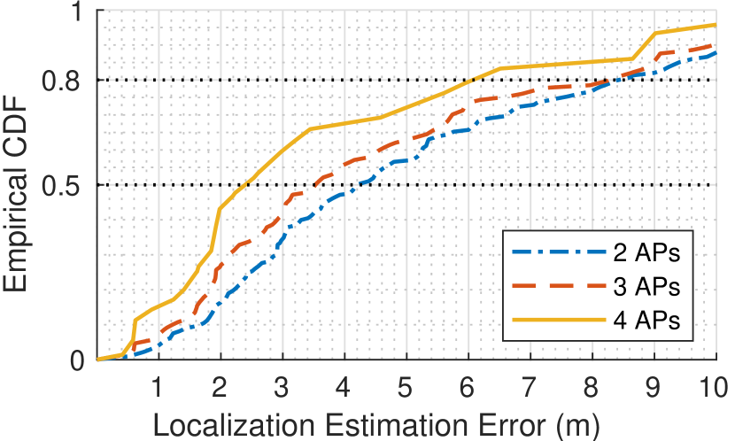
Seirios uses multiple-AP fusion for localization. As shown in Fig. 6, fusing more APs can reduce the ambiguity of localization estimation and increase its accuracy. To investigate how the number of APs affects the overall performance, we evaluated the localization errors with two, three, and four APs, respectively.
For outdoor environments, we first evaluated two APs with C and D, as shown in Fig 10, and then added APs B and A sequentially for the evaluation of three and four APs, respectively. The results are shown in Fig. 12(c). With two APs, the median and 80th percentile errors are 14.8 m and 26.0 m, respectively. By increasing the number of APs from two to three, the median and 80th percentile errors are reduced to 8.8 m and 17.0 m, respectively. With four APs, the median error is reduced by 50% of those with three APs and 70% of those with two APs to 4.4 m, and the 80th percentile error is reduced to 6.4 m.
For indoor environments, we observe similar behavior, as shown in Fig. 12(d). Here, the error reduction with four APs for indoors is 31% compared to that of three APs and 42% compared to that of two APs, respectively, which is less than that of outdoor calculations. The reason is that the indoor area is smaller than the outdoor area, but both are equipped with the same number of APs, which means that the indoor area has better LoRaWAN coverage than the outdoor area. Thus, the improvement with extra APs indoors is not as significant as that outdoors.
Overall, the evaluation shows that localization accuracy relates to the density of APs (gateways) and proves the effectiveness of AP fusion algorithm introduced in Sec. 4.6.
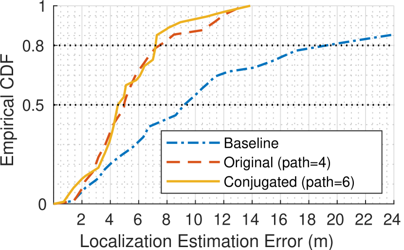
7.6. Effectiveness of Conjugates
Sec. 4.5 proposed to use conjugated ESPRIT to increase the capability of multipath resolution. Theoretically, the proposed algorithm can increase the capacity for multipaths resolution from four to six in our setting (i.e., one AP prototype with two antennas).
Fig. 12(f) shows the localization accuracy achieved by the conventional ESPRIT, the conjugated ESPRIT, and the baseline in the indoor evaluation. The median errors for the aforementioned three algorithms are 2.4 m, 3.9 m and 4.6 m, respectively. Evidently, the conjugated ESPRIT reduced the error significantly. However, Fig. 12(e) shows that the conjugated ESPRIT for the outdoor environment does not have as significant an improvement as that of the indoor environment (Fig. 12(f)). This is because the outdoor environment has fewer multipaths that can even be solved by the conventional ESPRIT. Further, Figs. 12(f) and 12(e) imply that the number of significant multipaths indoors is more than four, while that for the outdoors is less than or equal to four.
8. Limitations and Future Work
One limitation of our research is that Seirios focuses on one transmitter only and does not support concurrent transmissions from other LoRaWAN devices. However, since LoRa networks benefit hugely from the innate orthogonality of SFs, we believe that concurrent transmissions can be regarded as the noise and suppressed by the super-resolution algorithms (Schmidt, 1986; Roy et al., 1986; Roy and Kailath, 1989). In this regard, Seirios can potentially locate multiple transmitters at the same time. Nevertheless, we leave research in this direction as future work.
Another limitation is the number of gateways in practice. Normally, one LoRaWAN gateway can cover up to 10 km and thus the density of deployment is low, which is different to our evaluation setup in Sec.7.5 with multiple gateways for high localization accuracy. However, recent research (Dongare et al., 2018; Liu et al., 2020) shows that a dense deployment of LoRaWAN gateways improves signal quality, battery lifetime, network scalability and network robustness. We envision the dense deployment of LoRaWAN gateways in the future and leave how the gateway deployment density influences localization performance as future work.
In future work, it will be interesting to investigate if the localization performance of Seirios can be further improved by other signal super resolution algorithms, such as compressive sensing and matrix pencil decomposition, and by combining the information from other radio signals such as Wi-Fi and BLE in more cluttered environments.
9. Conclusion
This paper introduced Seirios, an AoA-based localization system for LoRaWAN devices. Despite the huge success and popularity of AoA-based localization methods in wideband radio systems such as Wi-Fi, no prior studies have explored this method for the emerging narrowband LoRaWAN signal because of the bandwidth limitation that results in poor location estimation. Seirios addresses this limitation using a novel (non-overlapped) interchannel synchronization method and an ESPRIT algorithm that exploits both the original and the conjugate of the channel state measurements. Our empirical evaluation shows that Seirios can reduce localization errors by 41.6% compared to the baseline, and can achieve 4.4 m median accuracy in an open area of 100 m 60 m as well as 2.4 m median accuracy in an indoor area of 25 m 15 m.
References
- (1)
- Adelantado et al. (2017) Ferran Adelantado, Xavier Vilajosana, Pere Tuset-Peiro, Borja Martinez, Joan Melia-Segui, and Thomas Watteyne. 2017. Understanding the limits of LoRaWAN. IEEE Communications magazine 55, 9 (2017), 34–40. https://doi.org/10.1109/MCOM.2017.1600613
- Aernouts et al. (2020) Michiel Aernouts, Noori BniLam, Rafael Berkvens, and Maarten Weyn. 2020. TDAoA: A combination of TDoA and AoA localization with LoRaWAN. Internet of Things 11 (2020), 100236.
- Bansal et al. (2021) Atul Bansal, Akshay Gadre, Vaibhav Singh, Anthony Rowe, Bob Iannucci, and Swarun Kumar. 2021. OwLL: Accurate LoRa Localization using the TV Whitespaces. In Proceedings of the 20th International Conference on Information Processing in Sensor Networks (co-located with CPS-IoT Week 2021). 148–162.
- Bargh and de Groote (2008) Mortaza S Bargh and Robert de Groote. 2008. Indoor localization based on response rate of bluetooth inquiries. In Proceedings of the first ACM international workshop on Mobile entity localization and tracking in GPS-less environments. 49–54.
- Chen et al. (2019) Lili Chen, Jie Xiong, Xiaojiang Chen, Sunghoon Ivan Lee, Kai Chen, Dianhe Han, Dingyi Fang, Zhanyong Tang, and Zheng Wang. 2019. WideSee: Towards wide-area contactless wireless sensing. In SenSys 2019 - Proceedings of the 17th Conference on Embedded Networked Sensor Systems. 258–270. https://doi.org/10.1145/3356250.3360031
- Chiani and Elzanaty (2019) Marco Chiani and Ahmed Elzanaty. 2019. On the LoRa modulation for IoT: Waveform properties and spectral analysis. IEEE Internet of Things Journal 6, 5 (2019), 8463–8470. https://doi.org/10.1109/JIOT.2019.2919151
- Chintalapudi et al. (2010) Krishna Chintalapudi, Anand Padmanabha Iyer, and Venkata N Padmanabhan. 2010. Indoor localization without the pain. In Proceedings of the Annual International Conference on Mobile Computing and Networking, MOBICOM. 173–184. https://doi.org/10.1145/1859995.1860016
- de Carvalho Silva et al. (2017) Jonathan de Carvalho Silva, Joel JPC Rodrigues, Antonio M Alberti, Petar Solic, and Andre LL Aquino. 2017. LoRaWAN—A low power WAN protocol for Internet of Things: A review and opportunities. In 2017 2nd International Multidisciplinary Conference on Computer and Energy Science (SpliTech). IEEE, 1–6.
- Dongare et al. (2018) Adwait Dongare, Revathy Narayanan, Akshay Gadre, Anh Luong, Artur Balanuta, Swarun Kumar, Bob Iannucci, and Anthony Rowe. 2018. Charm: Exploiting Geographical Diversity Through Coherent Combining in Low-power Wide-area Networks. In Proceedings of the 17th ACM/IEEE International Conference on Information Processing in Sensor Networks (IPSN ’18). IEEE Press, Piscataway, NJ, USA, 60–71. https://doi.org/10.1109/IPSN.2018.00013
- Evans (1981) JE Evans. 1981. High resolution angular spectrum estimation technique for terrain scattering analysis and angle of arrival estimation. In 1st IEEE ASSP Workshop Spectral Estimat., McMaster Univ., Hamilton, Ont., Canada, 1981. 134–139.
- Gadre et al. (2020) Akshay Gadre, Revathy Narayanan, Anh Luong, Anthony Rowe, Bob Iannucci, and Swarun Kumar. 2020. Frequency configuration for low-power wide-area networks in a heartbeat. In 17th USENIX Symposium on Networked Systems Design and Implementation (NSDI 20). 339–352.
- Ghanaatian et al. (2019) Reza Ghanaatian, Orion Afisiadis, Matthieu Cotting, and Andreas Burg. 2019. Lora digital receiver analysis and implementation. In ICASSP 2019-2019 IEEE International Conference on Acoustics, Speech and Signal Processing (ICASSP). IEEE, 1498–1502.
- Gu et al. (2018) Chaojie Gu, Linshan Jiang, and Rui Tan. 2018. LoRa-Based Localization: Opportunities and Challenges. (2018). arXiv:1812.11481
- Hou and Arslan (2017) Xiaoyue Hou and Tughrul Arslan. 2017. Monte Carlo localization algorithm for indoor positioning using Bluetooth low energy devices. In 2017 International Conference on Localization and GNSS (ICL-GNSS). IEEE, 1–6.
- Hu et al. (2014) Anzhong Hu, Tiejun Lv, Hui Gao, Zhang Zhang, and Shaoshi Yang. 2014. An ESPRIT-based approach for 2-D localization of incoherently distributed sources in massive MIMO systems. IEEE Journal of Selected Topics in Signal Processing 8, 5 (2014), 996–1011.
- Iliev and Paprotny (2015) Nick Iliev and Igor Paprotny. 2015. Review and Comparison of Spatial Localization Methods for Low-Power Wireless Sensor Networks. IEEE Sensors Journal 15, 10 (2015), 5971–5987. https://doi.org/10.1109/JSEN.2015.2450742
- Islam et al. (2019) Bashima Islam, Md Tamzeed Islam, Jasleen Kaur, and Shahriar Nirjon. 2019. Lorain: Making a case for lora in indoor localization. In 2019 IEEE International Conference on Pervasive Computing and Communications Workshops (PerCom Workshops). IEEE, 423–426.
- Joshi et al. (2015) Kiran Joshi, Dinesh Bharadia, Manikanta Kotaru, and Sachin Katti. 2015. WiDeo: Fine-grained device-free motion tracing using RF backscatter. In Proceedings of the 12th USENIX Symposium on Networked Systems Design and Implementation, NSDI 2015. 189–204.
- Kotaru et al. (2015) Manikanta Kotaru, Kiran Joshi, Dinesh Bharadia, and Sachin Katti. 2015. SpotFi: Decimeter level localization using WiFi. In SIGCOMM 2015 - Proceedings of the 2015 ACM Conference on Special Interest Group on Data Communication. 269–282. https://doi.org/10.1145/2785956.2787487
- Kotaru and Katti (2018) Manikanta Kotaru and Sachin Katti. 2018. Position tracking for virtual reality using commodity WiFi. In Proceedings of the Annual International Conference on Mobile Computing and Networking, MOBICOM. 15–17. https://doi.org/10.1145/3264877.3264882
- Kumar et al. (2014) Swarun Kumar, Ezzeldin Hamed, Dina Katabi, and Li Erran Li. 2014. LTE radio analytics made easy and accessible. ACM SIGCOMM Computer Communication Review 44, 4 (2014), 211–222.
- Lazik et al. (2015) Patrick Lazik, Niranjini Rajagopal, Oliver Shih, Bruno Sinopoli, and Anthony Rowe. 2015. ALPS: A bluetooth and ultrasound platform for mapping and localization. In Proceedings of the 13th ACM conference on embedded networked sensor systems. 73–84.
- Li et al. (2016) Xiang Li, Shengjie Li, Daqing Zhang, Jie Xiong, Yasha Wang, and Hong Mei. 2016. Dynamic-MUSIC: Accurate Device-Free Indoor Localization. In Proceedings of the 2016 ACM International Joint Conference on Pervasive and Ubiquitous Computing (Heidelberg, Germany) (UbiComp ’16). 196–207. https://doi.org/10.1145/2971648.2971665
- Li et al. (2020) You Li, Yuan Zhuang, Xin Hu, Zhouzheng Gao, Jia Hu, Long Chen, Zhe He, Ling Pei, Kejie Chen, Maosong Wang, et al. 2020. Location-Enabled IoT (LE-IoT): A Survey of Positioning Techniques, Error Sources, and Mitigation. arXiv preprint arXiv:2004.03738 (2020).
- Liando et al. (2019) Jansen C Liando, Amalinda Gamage, Agustinus W Tengourtius, and Mo Li. 2019. Known and unknown facts of LoRa: Experiences from a large-scale measurement study. ACM Transactions on Sensor Networks (TOSN) 15, 2 (2019), 1–35.
- Liu et al. (2007) Hui Liu, Houshang Darabi, Pat Banerjee, and Jing Liu. 2007. Survey of wireless indoor positioning techniques and systems. IEEE Transactions on Systems, Man, and Cybernetics, Part C (Applications and Reviews) 37, 6 (2007), 1067–1080.
- Liu et al. (2020) Jun Liu, Weitao Xu, Sanjay Jha, and Wen Hu. 2020. Nephalai: towards LPWAN C-RAN with physical layer compression. In Proceedings of the 26th Annual International Conference on Mobile Computing and Networking. 1–12.
- LoRa Alliance (2017) LoRa Alliance. 2017. LoRaWAN 1.1 Specification. LoRa Alliance 1.1 (2017), 101.
- Ma et al. (2017) Yunfei Ma, Nicholas Selby, and Fadel Adib. 2017. Minding the billions: Ultra-wideband localization for deployed rfid tags. In Proceedings of the 23rd annual international conference on mobile computing and networking. 248–260.
- Ma et al. (2019) Yongsen Ma, Gang Zhou, and Shuangquan Wang. 2019. WiFi sensing with channel state information: A survey. ACM Computing Surveys (CSUR) 52, 3 (2019), 1–36. https://doi.org/10.1145/3310194
- Nandakumar et al. (2018) Rajalakshmi Nandakumar, Vikram Iyer, and Shyamnath Gollakota. 2018. 3D localization for sub-centimeter sized devices. In SenSys 2018 - Proceedings of the 16th Conference on Embedded Networked Sensor Systems. 108–119. https://doi.org/10.1145/3274783.3274851
- Oumar et al. (2012) Ousmane Abdoulaye Oumar, Ming Fei Siyau, and Tariq P Sattar. 2012. Comparison between MUSIC and ESPRIT direction of arrival estimation algorithms for wireless communication systems. In The First International Conference on Future Generation Communication Technologies. IEEE, 99–103.
- Pan et al. (2020) Jingjing Pan, Meng Sun, Yide Wang, and Xiaofei Zhang. 2020. An enhanced spatial smoothing technique with ESPRIT algorithm for direction of arrival estimation in coherent scenarios. IEEE Transactions on Signal Processing 68 (2020), 3635–3643.
- Peng et al. (2018) Yao Peng, Longfei Shangguan, Yue Hu, Yujie Qian, Xianshang Lin, Xiaojiang Chen, Dingyi Fang, and Kyle Jamieson. 2018. PLoRa: A passive long-range data network from ambient LoRa transmissions. In Proceedings of the 2018 Conference of the ACM Special Interest Group on Data Communication. 147–160. https://doi.org/10.1145/3230543.3230567
- Pillai and Kwon (1989) S Unnikrishna Pillai and Byung Ho Kwon. 1989. Forward/backward spatial smoothing techniques for coherent signal identification. IEEE Transactions on Acoustics, Speech, and Signal Processing 37, 1 (1989), 8–15.
- Podevijn et al. (2018) Nico Podevijn, David Plets, Jens Trogh, Luc Martens, Pieter Suanet, Kim Hendrikse, and Wout Joseph. 2018. TDoA-based outdoor positioning with tracking algorithm in a public LoRa network. Wireless Communications and Mobile Computing 2018 (2018).
- Roy and Kailath (1989) Richard Roy and Thomas Kailath. 1989. ESPRIT-estimation of signal parameters via rotational invariance techniques. IEEE Transactions on acoustics, speech, and signal processing 37, 7 (1989), 984–995.
- Roy et al. (1986) Robert Roy, Arogyaswami Paulraj, and Thomas Kailath. 1986. ESPRIT–A subspace rotation approach to estimation of parameters of cisoids in noise. IEEE transactions on acoustics, speech, and signal processing 34, 5 (1986), 1340–1342.
- Schmid et al. (2010) Johannes Schmid, Markus Völker, Tobias Gädeke, Pascal Weber, Wilhelm Stork, and Klaus D Müller-Glaser. 2010. An approach to infrastructure-independent person localization with an IEEE 802.15. 4 WSN. In 2010 International Conference on Indoor Positioning and Indoor Navigation. IEEE, 1–9.
- Schmidt (1986) Ralph Schmidt. 1986. Multiple emitter location and signal parameter estimation. IEEE transactions on antennas and propagation 34, 3 (1986), 276–280.
- Soltanaghaei et al. (2018) Elahe Soltanaghaei, Avinash Kalyanaraman, and Kamin Whitehouse. 2018. Multipath triangulation: Decimeter-level WiFi localization and orientation with a single unaided receiver. In MobiSys 2018 - Proceedings of the 16th ACM International Conference on Mobile Systems, Applications, and Services. ACM, 376–388. https://doi.org/10.1145/3210240.3210347
- Sun et al. (2005) Guolin Sun, Jie Chen, Wei Guo, and KJ Ray Liu. 2005. Signal processing techniques in network-aided positioning: a survey of state-of-the-art positioning designs. IEEE signal processing magazine 22, 4 (2005), 12–23.
- Talla et al. (2017) Vamsi Talla, Mehrdad Hessar, Bryce Kellogg, Ali Najafi, Joshua R Smith, and Shyamnath Gollakota. 2017. Lora backscatter: Enabling the vision of ubiquitous connectivity. Proceedings of the ACM on Interactive, Mobile, Wearable and Ubiquitous Technologies 1, 3, 1–24. https://doi.org/10.1145/3130970
- Vasisht et al. (2016) Deepak Vasisht, Swarun Kumar, and Dina Katabi. 2016. Decimeter-level localization with a single WiFi access point. In Proceedings of the 13th USENIX Symposium on Networked Systems Design and Implementation, NSDI 2016. 165–178.
- Vasisht et al. (2018) Deepak Vasisht, Guo Zhang, Omid Abari, Hsiao Ming Lu, Jacob Flanz, and Dina Katabi. 2018. In-body backscatter communication and localization. In SIGCOMM 2018 - Proceedings of the 2018 Conference of the ACM Special Interest Group on Data Communication. Association for Computing Machinery, Inc, 132–146. https://doi.org/10.1145/3230543.3230565
- Wang et al. (2016) Ju Wang, Hongbo Jiang, Jie Xiong, Kyle Jamieson, Xiaojiang Chen, Dingyi Fang, and Binbin Xie. 2016. LiFS: Low Human-Effort, Device-Free Localization with Fine-Grained Subcarrier Information. In Proceedings of the 22nd Annual International Conference on Mobile Computing and Networking (MobiCom ’16). 243–256. https://doi.org/10.1145/2973750.2973776
- Wang et al. (2017) Ju Wang, Jie Xiong, Hongbo Jiang, Xiaojiang Chen, and Dingyi Fang. 2017. D-watch: Embracing “bad” multipaths for device-free localization with cots rfid devices. IEEE/ACM Transactions on Networking 25, 6 (2017), 3559–3572. https://doi.org/10.1109/TNET.2017.2747583
- Wolf et al. (2018) Florian Wolf, Christophe Villien, Sébastien de Rivaz, François Dehmas, and Jean-Pierre Cances. 2018. Improved multi-channel ranging precision bound for narrowband LPWAN in multipath scenarios. In 2018 IEEE Wireless Communications and Networking Conference (WCNC). IEEE, 1–6.
- Xie and Xiong (2020) Binbin Xie and Jie Xiong. 2020. Combating interference for long range LoRa sensing. In Proceedings of the 18th Conference on Embedded Networked Sensor Systems. 69–81. https://doi.org/10.1145/3384419.3430731
- Xie et al. (2019) Yaxiong Xie, Mo Li, Jie Xiong, and Kyle Jamieson. 2019. MD-Track: Leveraging multi-dimensionality in passive indoor Wi-Fi tracking. In Proceedings of the Annual International Conference on Mobile Computing and Networking, MOBICOM. https://doi.org/10.1145/3300061.3300133 arXiv:1812.03103
- Xiong and Jamieson (2013) Jie Xiong and Kyle Jamieson. 2013. ArrayTrack: A fine-grained indoor location system. In Proceedings of the 10th USENIX Symposium on Networked Systems Design and Implementation, NSDI 2013. 71–84.
- Xiong and Jamieson (2015) Jie Xiong and Kyle Jamieson. 2015. ToneTrack : Leveraging Frequency-Agile Radios for Time-Based Indoor Wireless Localization Categories and Subject Descriptors. In Proceedings of the Annual International Conference on Mobile Computing and Networking, MOBICOM. 537–549.
- Xu et al. (2019) Weitao Xu, Jun Young Kim, Walter Huang, Salil S Kanhere, Sanjay K Jha, and Wen Hu. 2019. Measurement, characterization, and modeling of lora technology in multifloor buildings. IEEE Internet of Things Journal 7, 1 (2019), 298–310.
- Xu et al. (2019) W. Xu, J. Zhang, J. Y. Kim, W. Huang, S. S. Kanhere, S. K. Jha, and W. Hu. 2019. The Design, Implementation, and Deployment of a Smart Lighting System for Smart Buildings. IEEE Internet of Things Journal 6, 4 (2019), 7266–7281.
- Zhang et al. (2020) Fusang Zhang, Zhaoxin Chang, Kai Niu, Jie Xiong, Beihong Jin, Qin Lv, and Daqing Zhang. 2020. Exploring LoRa for Long-range Through-wall Sensing. In Proceedings of the ACM on Interactive, Mobile, Wearable and Ubiquitous Technologies, Vol. 4. ACM New York, NY, USA, 1–27.