Dielectric manipulation of polymer translocation dynamics in engineered membrane nanopores
Abstract
ABSTRACT: The alteration of the dielectric membrane properties by membrane engineering techniques such as carbon nanotube (CNT) coating opens the way to novel molecular transport strategies for biosensing purposes. In this article, we predict a macromolecular transport mechanism enabling the dielectric manipulation of the polymer translocation dynamics in dielectric membrane pores confining mixed electrolytes. In the giant permittivity regime of these engineered membranes governed by attractive polarization forces, multivalent ions adsorbed by the membrane nanopore trigger a monovalent ion separation and set an electroosmotic counterion flow. The drag force exerted by this flow is sufficiently strong to suppress and invert the electrophoretic velocity of anionic polymers, and also to generate the mobility of neutral polymers whose speed and direction can be solely adjusted by the charge and concentration of the added multivalent ions. These features identify the dielectrically generated transport mechanism as an efficient mean to drive overall neutral or weakly charged analytes that cannot be controlled by an external voltage. We also reveal that in anionic polymer translocation, multivalent cation addition into the monovalent salt solution amplifies the electric current signal by several factors. The signal amplification is caused by the electrostatic many-body interactions replacing the monovalent polymer counterions by the multivalent cations of higher electric mobility. The strength of this elektrokinetic charge discrimination points out the potential of multivalent ions as current amplifiers capable of providing boosted resolution in nanopore-based biosensing techniques.
pacs:
05.20.Jj,82.45.Gj,82.35.RsI Introduction
Macromolecular transport under nanoscale confinement lies at the heart of various in vivo and in vitro biological phenomena. From the artificial delivery of genetic material into the cell medium gn1 ; gn2 ; gn3 to viral infection biomatter and nanopore-based biosequencing rev2 ; com , our understanding and control of these processes rely on the accurate characterization of the macromolecular dynamics in the confined liquid environment. Among the aforementioned processes, the characterization and optimization of the field-driven DNA translocation is a crucial technical step to meet this challenge. However, due to the diversity of the competing electrostatic, hydrodynamic, and entropic effects driving the confined polymer-liquid complex, a complete prescription for the sequence detection by translocation is still missing Tapsarev .
The experimentally gained insight into the nanopore sensing approaches indicates that the primary requirement for the resolution of single nucleotides is a strong current signal of long duration e1 ; e2 ; e6 ; e4 ; e5 ; e3 ; e7 ; e8 ; e9 ; e10 ; Coating1 ; Coating2 ; Coating3 . This technical constraint implies the necessity to identify the physical conditions maximizing the mean dwell time spent by the analyte inside the nanopore. Accounting for the effect of polymer conformations and steric polymer-membrane interactions on the translocation process, the connection between the dwell time and the polymer length has been initially characterized by numerical studies n1 ; n2 ; n5 , scaling approaches Wolterink , and the tension propagation theory Saka1 ; Saka2 . Subsequently, the consideration of the electrostatic and non-equilibrium nature of the translocation process led to modified Smoluchowski formalisms mut1 ; mut2 ; mut3 ; Chinappi2 ; HLsim ; cap1 ; cap2 and simulation models aks1 ; aks2 ; aks3 ; Hsiao probing the effect of the electrostatic control parameters such as the external voltage, salt, and the acidity of the solution on the polymer capture and translocation dynamics.
Field-driven polymer translocation occurs via the collective motion of the macromolecule and the surrounding salt ions hydrated in water. This implies that the quantitatively accurate characterization of polymer translocation requires the modeling of the pore electrostatics and hydrodynamics on an equal footing. Based on the coupling of the Stokes relation and the linearized mean-field (MF) Poisson-Boltzmann (PB) equation, Ghosal developed the first electrohydrodynamic (EH) theory of polymer translocation through solid-state pores Ghosal2006 ; Ghosal2007 . Within the one-loop theory of electrostatic interactions, we incorporated into this EH formalism the weak-coupling (WC) ion correlations the16 . Finally, by taking into account the additional effect of the electrostatic polymer-membrane interactions, we showed that the presence of multivalent ions enables faster polymer capture and slower translocation by like-charge polymer-membrane attraction Buyuk2018 ; Buyuk2018II .
In interfacially charged solid-state nanopores, the polymer velocity can be equally altered by the action of the electroosmotic (EO) flows aks2 . However, the control of these flows requires the adjustment of the nanopore surface charge via the acidity of the buffer solution, which equally modifies the polymer surface charge subjected to protonation Firnkes . The resulting complexity of the H-dependent translocation rates Buyuk2018III indicates the necessity to tune the translocation speed without activating the surface chemistry of the polymer. In this article, we show that via the adequate choice of the electrolyte composition, the dielectric properties of engineered substrates such as CNT-coated membranes Coating4 ; Coating5 allow to generate EO flows whose magnitude and direction can be controlled without affecting the polymer surface charge.
The use of coated-membranes for polymer translocation purposes has been initially motivated by the need to prevent the undesired adhesion of the translocating molecule to the membrane surface Coating1 . Further studies revealed that membrane coating equally enables the modification of the threading force on DNA Coating2 and the reduction of the translocation velocity by edge-pinning the molecule at the pore mouth Coating3 . The coating of polymer-based matrices by CNTs has been independently initiated by the technological requirement to fabricate compact micro capacitors of high dielectric permittivity. Indeed, the dressing of the membrane surfaces with CNTs was revealed to amplify the dielectric permittivity of the substrate by orders of magnitude Coating4 ; Coating5 .
In the present work, we explore the potential of dielectric membrane nanopores confining electrolyte mixtures for polymer translocation purposes. At this point, it should be noted that the accurate modeling of mixed electrolytes requires the asymmetric treatment of the ionic valencies characterized by different electrostatic coupling strengths NetzSC ; Podgornik2010 ; Buyuk2019 . With the aim to investigate correlation and polarization effects on nanofluidic ion transport through planar slits Boc1 ; Boc2 ; Heyden2006 ; Gillespie2013 , we have recently developed the SC (strong coupling)-dressed PB (SCPB) theory consistently treating the mono- and multivalent ions within the WC and SC electrostatics, respectively JPCB2020 . Here, we adapt the SCPB approach to the cylindrical geometry of the polymer-nanopore complex. By coupling this electrostatic formalism with the hydrodynamic Stokes equation and the force-balance relation on the translocating polyelectrolyte, we develop the first correlation-dressed theory of ion and polymer transport accounting for the coexisting SC and WC electrostatics of the mono- and multivalent ion species, and the surface polarization forces originating from the dielectric contrast between the membrane matrix and the electrolyte.
Within this EH theory, we identify a new polymer translocation mechanism triggered by electrostatic many-body interactions and membrane polarization forces. Namely, our formalism reveals that due to the attractive polarization forces governing the giant permittivity regime of surface-coated membranes, added multivalent ions adsorbed by the neutral nanopore attract their monovalent counterions into the pore and reject their monovalent coions to the reservoir. Under the effect of the external voltage, this charge separation generates an EO counterion flow dragging the polymer at the velocity that can be tuned via the charge and amount of the added multivalent ions. The dielectrically generated translocation mechanism is therefore a central prediction for the transport of overall neutral or weakly charged molecules that cannot be controlled by an external voltage.
We characterize as well the effect of the electrolyte composition on the current signal generated by anionic polymer translocation events. We find that upon addition of multivalent cations such as spermidine or cobalt charges into the monovalent salt reservoir, electrostatic many-body interactions replace the monovalent salt counterions bound to the translocating polyelectrolyte by the multivalent counterions of higher electric mobility. This charge discrimination amplifies the electric current signal by several factors. Considering the correlation between the ionic current strength and the single nucleotide resolution in biosequencing by translocation, the multivalent counterion-induced signal amplification is a key observation for nanopore-based sensing applications.
II Theory
We introduce here the electrostatic model of the polymer-electrolyte complex confined to a nanopore. Then, we combine this formalism with the hydrodynamic Stokes theory, and derive the polymer translocation velocity and charge current through the pore.
II.1 Electrostatic model
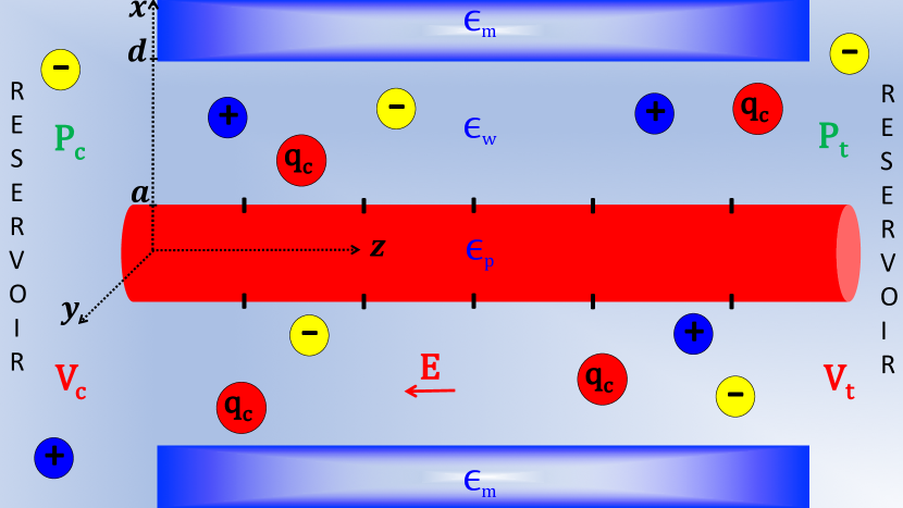
Fig. 1 depicts the configuration of the polymer-electrolyte complex. The confined polymer is modeled as a rigid cylinder of radius nm, length , dielectric permittivity , and surface charge density . The field-driven translocation takes place along the axis of the uncharged cylindrical membrane nanopore of radius and length nt1 . Hence, the off-axis and conformational polymer fluctuations are neglected. Moreover, as our model does not include the molecular details of CNTs, the alteration of the dielectric substrate permittivity by surface engineering techniques Coating4 ; Coating5 will be approximately taken into account by the uniform membrane permittivity coefficient .
The charged liquid located between the translocating polymer and the nanopore is modeled within the dielectric continuum electrostatics. Thus, the medium is characterized by the piecewise dielectric permittivity distribution
| (1) |
where is the water permittivity. The confined liquid contains an ionic mixture composed of a monovalent salt solution such as KCl or NaCl, with the ionic valencies and bulk concentrations , and a third multivalent ion species of valency and concentration . From now on, the monovalent cation, anion, and multivalent ion species will be denoted by the symbols , , and , respectively.
In our formalism, the mobile ions are modeled as point charges interacting via the Coulomb potential. That is, ion specific effects associated with the extended charge structure and ionic hydration are neglected. Thus, the different ionic species in the liquid mixture are discerned in our model solely by their valency. The aforementioned approximations are based on the confluent results of nanofluidic ExpHey and polymer transport experiments poltrex1 ; poltrex2 ; poltrex3 indicating the leading role of the ionic multivalency in the emergence of correlation effects on charge transport characterized in this work. Via the comparative discussion of these experiments and our theoretical results, this point will be further elaborated in the Conclusions.
The technical details of the SCPB formalism used in our study can be found in Ref. JPCB2020 . This formalism treats the mono- and multivalent ions within the WC and SC electrostatics, respectively. In the Supporting Information, we review the key aspects of the SCPB theory and adapt the formalism to the cylindrical geometry of the polymer-nanopore system. We show that the SCPB equation for the electrostatic potential has the form of a radial Poisson equation,
| (2) |
with the Bjerrum length Å, the liquid charge density
| (3) |
and the ion number density . In Eq. (2), the radial coordinate of the polymer charges differs from the dielectric radii in Eq. (1) by the characteristic length Å. The length takes into account the location of the surface charge groups within the aqueous medium as well as the hydrodynamic no-slip condition at the polymer and pore surfaces.
II.2 Convective liquid and polymer velocities
Under the externally applied voltage and the hydrostatic pressure gradient , the convective velocity of the electrolyte experiencing the electric field obeys the Stokes equation , with the water viscosity Pa s and the electron charge . Combining the Stokes relation and the SCPB equation (2), and integrating, the convective liquid velocity follows as
| (4) |
where we used the electrophoretic (EP) mobility coefficient . In order to determine the integration constants , we account for the force-balance relation on the polymer, with the surface density of the electrostatic force and the hydrodynamic shear force . Imposing to Eq. (4) the resulting constraint , and the no-slip conditions and where , the liquid and polymer velocities follow in the form
II.3 Electric and streaming currents
The ionic current through the pore of cross-sectional area reads
| (7) |
In Eq. (7), the total ion velocity is given by the superposition of the convective hydrodynamic velocity (II.2), and the conductive velocity including the ionic mobilities ionm . Using the SCPB equation (2), and performing integrations by parts, the ionic current follows in the form of the linear response relation , with the electric and streaming conductances respectively given by
| (9) | |||||
The electric conductance (II.3) is composed of the conductive flow component (first term) typically dominating the EO component (second term) Gillespie2013 . Then, the first line of the streaming conductance (9) is associated with the free ion contribution to the charge flow. In polymer-free open pores (), the sign of the streaming current is set by the sign of the zeta potential term bringing the major contribution JPCB2020 . In the case of a translocating polymer, this free ion component is augmented by the second line of Eq. (9) proportional to the pressure-driven polymer mobility in Eq. (II.2). This additional term brings in turn the ionic current contribution from the cations bound to the translocating molecule.
III Results and discussion
III.1 Effect of the membrane polarization on the polymer mobility
We characterize here the effect of the membrane polarization forces on the electric field-driven polymer mobility in dielectric membrane nanopores confining multivalent electrolytes. Thus, we turn off the pressure (), and set the model parameters to the characteristic pore radius nm, length nm, and external voltage mV of the translocation experiments exp2 .
III.1.1 Generation of field-driven neutral polymer mobility
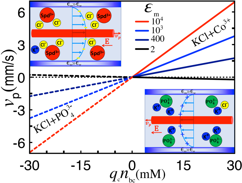
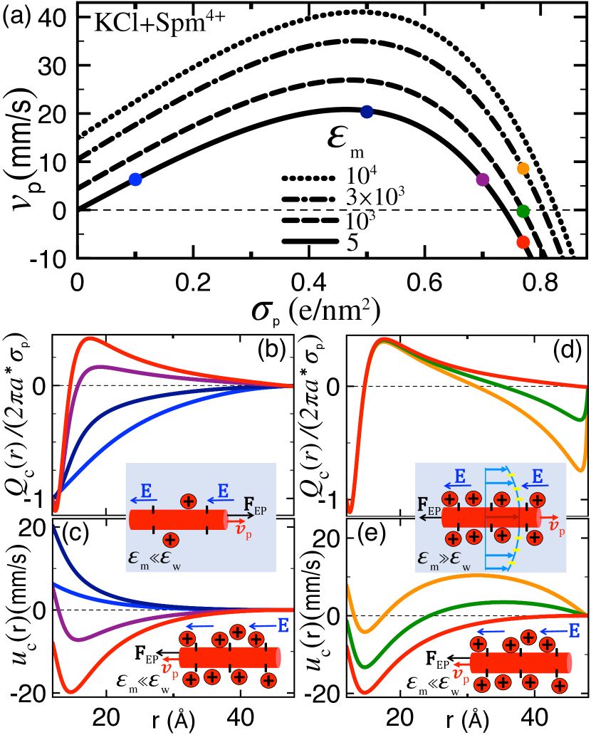
Fig. 2 displays the translocation velocity (II.2) of a neutral protein such as avidin at the point of zero charge () Firnkes against the multivalent charge density in the liquid mixtures including trivalent cations () such as spermidine or cobalt (solid curves), or trivalent anions () such as phosphate (dashed curves). At the dielectric permittivity value of uncoated silicon membranes (black), the vanishingly small velocity exhibits an irrelevant dependence on the multivalent ion concentration. However, in the high permittivity regime of engineered membrane pores, added trivalent cations trigger a finite polymer mobility opposite to the external electric field (), and the addition of trivalent anions induces a mobility along the electric field (). Moreover, the mobility grows uniformly with the membrane permittivity (), and the polymer velocity evolves linearly with the multivalent charge density, i.e. .
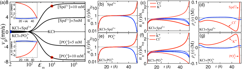
The variation of the polymer velocity with the membrane permittivity is explicitly illustrated in the main plot of Fig. 3(a). In pure symmetric monovalent salt such as KCl (dotted curve), the velocity vanishes at all permittivity values. However, in the presence of multivalent ions (solid curves), the increment of the membrane permittivity from the insulator () to the conductor regime () drives the translocation velocity from a vanishingly small to a positive value for added trivalent cations, and to a negative value with added trivalent anions. This indicates that in the giant permittivity regime of surface-coated pores, the valency and amount of the added multivalent ions can solely set the speed and direction of neutral or non-uniformly charged polymers that cannot be directly controlled by an external electric field.
Figs. 3(b)-(d) illustrate for the liquid mixture including trivalent cations () the mechanism triggering the neutral polymer mobility in terms of the charge densities. The membrane permittivity of each curve corresponds to the dot of the same color in Fig. 3(a). Fig. 3(b) shows that upon the rise of the permittivity from the insulator (blue) to the conductor regime (red), the inversion of the image-charge forces from repulsive to attractive leads to the adsorption of the trivalent cations from the reservoir to the pore wall, i.e. . In Fig. 3(c), one sees that the resulting interfacial layer acting as a cationic surface charge attracts monovalent anions () into the pore and excludes the monovalent cations () from the pore to the reservoir, i.e. nt3 . According to Fig. 3(d), in the central pore region occupied by the polymer, this charge separation gives rise to a monovalent anion-rich liquid of net negative charge (). The coupling of this anionic liquid to the external field sets an EO flow dragging the polymer opposite to the field, i.e. and (see the top insets of Figs. 2 and 3(a)).
Figs. 3(e)-(g) show that for the electrolyte including trivalent anions (), the transition from the insulator to the giant permittivity regime reverses this transport picture. Namely, the trivalent anions driven by the attractive polarization forces bring extra monovalent salt cations into the pore and reject the monovalent salt anions from the pore to the reservoir. This ion discrimination leads to a monovalent cation-rich liquid () and a cationic EO flow dragging the neutral polymer along the electric field, i.e. and (see the bottom insets of Figs. 2 and 3(a)).
III.1.2 Inverting the mobility of weakly anionic polymers
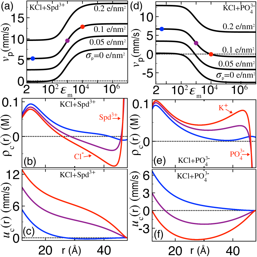
Having characterized the emergence of neutral polymer mobility from the polarization-induced EO flows, we scrutinize now the collective effect of these flows and the EP drag on the translocation of weakly anionic polymers such as deprotonated avidin molecules Firnkes . Fig. 4(a) shows that in the liquid containing trivalent cations, the transition from the insulator to the giant permittivity regime amplifies the positive EP polymer velocity. The mechanism driving this effect is displayed in the charge density and liquid velocity profiles of Figs. 4(b)-(c). In the insulating regime of silicon-based membranes (blue), the cation cloud () dragged by the electrophoretically translocating anionic polymer moves opposite to the electric field (). Then, in the large permittivity regime of engineered membrane nanopores governed by attractive polarization forces (purple and red), the monovalent anions attracted by the interfacially adsorbed trivalent cations invert the liquid charge from positive () to negative (). The resulting anionic EO flow moving opposite to the external electric field enhances the positive liquid and polymer velocities, i.e. .
Fig. 4(d) indicates that in the mixture containing trivalent anions, the rise of the membrane permittivity from the insulator to the conductor regime can suppress or even invert the EP polymer velocity. To shed light on this peculiarity, we note that according to Fig. 4(e), the monovalent cations attracted by the interfacial trivalent anion layer enhance the positive density of the counterion liquid around the anionic polymer. The coupling of this strongly cationic liquid to the electric field sets an EO current parallel with the field. Fig. 4(f) shows that the drag of this EO flow opposing the EP force inverts the sign of the liquid and polymer velocities from positive to negative, i.e. . In particular, at the membrane permittivity (red), the exact compensation of the EP drift by the EO flow stops entirely the translocation, i.e. .
III.1.3 Mobility inversion of strongly anionic biopolymers
In the experimentally studied case of strongly charged biopolymers such as DNA translocating in the highly multivalent KCl+ mixture poltrex1 ; poltrex2 ; poltrex3 , the polarization-driven EO flows are expected to act together with the strong-coupling correlations governing the vicinity of the polymer. With the aim to investigate the outcome of this coupling, we reported in Fig. 5(a) the surface charge dependence of the polymer velocity at various membrane permittivities for the electrolyte mixture composed of monovalent salt and tetravalent cations (). For moderate polymer charges , the increase of the charge density amplifies the electrostatic force and enhances steadily the polymer velocity, i.e. . However, in the strong polymer charge regime , this linear response behavior breaks down; therein, the rise of the polymer charge reduces the translocation velocity and inverts its sign from positive to negative.
The inverted velocity regime observed in experiments poltrex1 ; poltrex2 ; poltrex3 and simulations aks2 involving various multivalent charge species corresponds to an unconventional transport picture characterized by an anionic polymer translating parallel with the electric field. Figs. (5)(b)-(c) illustrate the underlying EH mechanism in terms of the cumulative charge nt2
| (10) |
and the liquid velocity (II.2) in the low permittivity regime of uncoated neutral pores () where EO flows are absent. In the case of moderately charged polymers (blue and navy), the partial screening of the polymer charges by the surrounding counterions results in a uniformly negative total charge (). This generates a liquid flow and a polymer mobility opposite to the field ( and ). Upon the increment of the polymer charge density to (red), enhanced correlations between the multivalent cations and polymer charges lead to the overcompensation of the latter by these counterions, and to the inversion of the cumulative charge from negative to positive (). The coupling of the field to this cationic polymer-liquid complex reverses the EP force, reorienting the liquid and polymer velocities along the field ( and ). This mechanism is depicted in the insets of Figs. 5(b)-(c).
In Figs. (5)(a)-(b), one notes that the intermediate charge strength (purple) gives rise to CI () without the polymer mobility reversal (). To elucidate this point, we combine Eqs. (II.2) and (10) to obtain the macroscopic force-balance relation
| (11) |
equating the EP force (l.h.s.) and the hydrodynamic shear force (r.h.s.) acting on the cylindrical liquid volume . Eq. (11) and Figs. 5(b)-(c) show that CI at results in a liquid velocity minimum () accompanied with an inverted EO flow (). However, the close inspection of Fig. 5(c) also shows that the flow inversion causes the reversal of the polymer velocity exclusively if the positive slope is large enough at . Thus, according to Eq. (11), the occurrence of polymer mobility inversion requires a strong enough reversed positive charge at .
Finally, Fig. 5(a) shows that in the inverted mobility phase, the increment of the membrane permittivity from the insulator (red) to the giant permittivity regime (green and orange) reverses the polymer velocity from negative back to positive. The mechanism behind the cancellation of mobility inversion is illustrated in Figs. 5(d)-(e). One notes that the attractive polarization forces emerging at high permittivities do not affect the cumulative charge and the associated EP force on the polymer-counterion complex at Å. However, in the outer liquid layer at Å, the monovalent anions attracted by the interfacially adsorbed tetravalent cations turn the cumulative charge from weakly positive to strongly negative. The resulting anionic flow of positive velocity drags the charge inverted polymer oppositely to the electric field (). Thus, in surface-coated pores located in the giant permittivity regime, the tetravalent cation-induced EO flows are expected to suppress the EP mobility inversion triggered by the same tetravalent charges in uncoated pores poltrex1 ; poltrex2 . The complex EH picture behind this prediction is illustrated in the insets of Figs. 5(d)-(e).
III.2 Polarization effects on the current signal
The dependence of the sequencing resolution on the strength of the current signal requires the identification of the experimentally tunable system features maximizing the magnitude of the current. Motivated by this point, we scrutinize here the influence of membrane coating and ion multivalency on the current signal generated by pressure and voltage-driven translocation events.
III.2.1 Streaming current signal
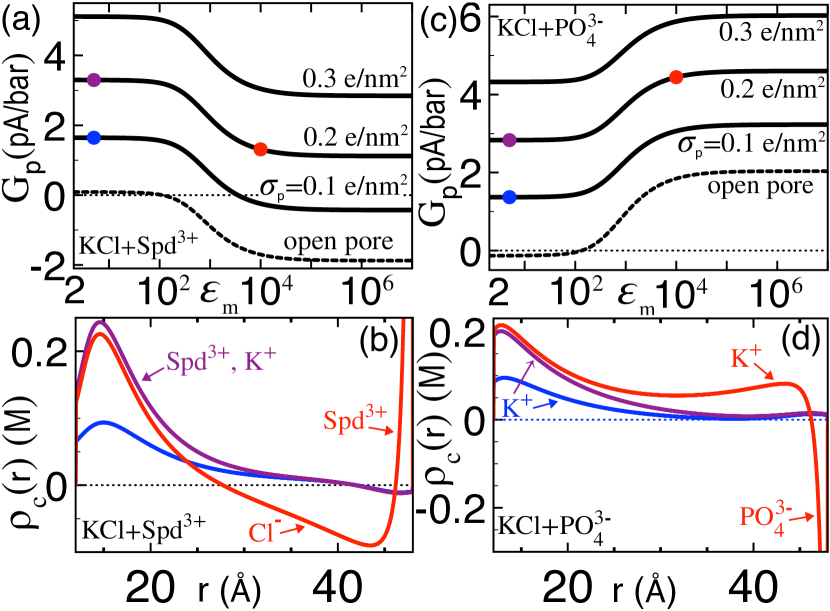
Fig. 6(a) displays the streaming current (9) induced by pressure-driven translocation versus the membrane permittivity in the liquid containing trivalent cations. This figure should be interpreted together with the charge density plot in Fig. 6(b). The latter indicates that during translocation through insulating membranes (blue and purple), the counterions attracted by the anionic polymer form a cationic layer around the molecule (). In Fig. 6(a), the comparison of the dashed (open pores) and solid curves (blocked pores) shows that this cation excess generates a positive current signal () corresponding to the second term of Eq. (9).
As the permittivity rises from the insulator (purple) to the giant permittivity regime (red), the cation-driven current is substantially suppressed (). This effect is driven by the charge separation mechanism scrutinized in Section III.1.2. Namely, Fig. 6(b) shows that in the conductor regime , the trivalent cations adsorbed by the polarization forces bring the monovalent anions close to the pore wall. The resulting anionic liquid layer suppresses the positive charge of the streaming flow () and weakens the cationic current through the nanopore.
Fig. 6(a) also shows that in the giant permittivity regime , the same monovalent anions generate a net negative streaming current through polymer-free open pores. The seemingly counterintuitive presence of a streaming current in an uncharged pore has been characterized in our recent work on ion transport thorough nanoslits JPCB2020 . The occurrence of these currents in the present nanopore geometry implies that in mixed electrolytes including trivalent cations, anionic polymer penetration into a surface-coated pore can reverse the streaming current from a negative to a positive value.
Finally, Figs. 6(c)-(d) illustrate the streaming current and the charge partition in the electrolyte containing trivalent anions. In the regime of insulating membranes (blue and purple), the attraction of the monovalent counterions, and the repulsion of the mono- and trivalent coions by the polymer charges generates a positive current signal. Moving to the giant permittivity regime (red), the extra monovalent cations attracted by the interfacially adsorbed trivalent anions positively add to the counterions brought by the translocating polyelectrolyte. This strengthens the positive mobile charge density and the streaming current through the pore, i.e. .
III.2.2 Amplification of the electric current signal by multivalent counterions
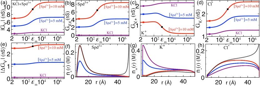
We predict herein the amplification of the electric current signal by multivalent counterions in anionic polymer translocation. Figs. 7(a)-(e) illustrate the electric conductance (II.3), the individual ion conductivities
| (12) |
with , and the conductivity change upon polymer penetration versus the membrane permittivity and trivalent counterion concentration. One notes that in insulating membrane pores (), added trivalent cations enhance the current by several factors () and amplify the net current signal from an insignificant value to a finite magnitude roughly proportional to the trivalent counterion concentration, i.e. .
Figs. 7(f)-(h) indicate that the signal amplification is set by the electrostatic many-body interactions replacing the monovalent counterions around the polymer by the trivalent counterions of higher electric mobility. Indeed, one sees that the increment of the bulk trivalent cation concentration from the purple to the blue and red curves enhances the density of the trivalent counterion layer around the polymer. However, these cations binding to the polymer charges exclude the monovalent counterions from the polymer surface and attract the monovalent coions into the pore, i.e. . Figs. 7(b)-(d) show that this charge separation enhances the and conductivities and lowers the conductivity of the nanopore, i.e. . Thus, in contrast with the purely monovalent salt solutions where the current signal is governed by the excess of monovalent counterions e6 ; the16 , the signal strength in the salt+ mixture is set by the excess of trivalent counterions accompanied with the monovalent counterion exclusion from the pore. This elektrokinetic charge discrimination is precisely responsible for the signal amplification in Fig 7(e).
Fig. 7(a) shows that in the salt+ liquid, the rise of the membrane permittivity from the insulator to the giant permittivity regime leads to a further amplification of the electric current (). The underlying charge configuration is displayed in Figs. 7(f)-(h). One sees that upon the transition from the insulator (red) to the conductor regime (black), the emerging polarization forces give rise to an additional adsorption peak close to the pore wall. This interfacial trivalent cation layer enhances the monovalent anion density and leads to further monovalent cation depletion from the pore, i.e. . Figs. 7(b)-(d) show that the corresponding charge discrimination results in the enhancement of the and conductivities and the reduction of the conductivity of the translocated pore, i.e. . Thus, the giant permittivity condition reached in surface-coated membranes strengthens the current amplification induced by multivalent counterions.
IV Conclusions
The accurate depiction of polymer translocation in mixed solutions requires the consideration of the multiple electrostatic coupling strengths associated with the distinct ionic valencies in the liquid. Within an EH theory combining the hydrodynamic Stokes relation and the electrostatic SCPB formalism fulfilling this requirement, we characterized the coupled effect of the ion multivalency and the membrane polarization forces on driven polymer translocation through dielectric membrane nanopores located in the giant permittivity regime.
Our formalism predicts that multivalent charge addition into a monovalent salt solution can solely trigger the voltage-driven mobility of neutral polymers through engineered membrane pores of giant permittivity. The effect is induced by the attractive membrane polarization forces adsorbing the multivalent ions into the nanopore. The resulting multivalent charge excess sets a monovalent ion separation and generates an EO counterion flow dragging the polymer through the pore. Due to the linear dependence of the polymer velocity on the charge and amount of the added multivalent ions, this EH process can be efficiently used to tune the mobility of overall neutral proteins that cannot be directly controlled by an electric field. This indicates that the polarization-driven polymer transport mechanism is a prediction of high relevance for nanopore-based biosensing technologies.
In the case of anionic polymer translocation, we showed that the multivalent cation-induced EO flows enhance the EP polymer mobility whereas multivalent anion addition reduces and even inverts the polymer velocity. Applying the transport formalism to the charge configuration of the translocation experiments conducted with strongly charged biopolymers in the KCl+ mixture, we found that the tetravalent cation-induced EO flows in surface-coated pores suppress the experimentally observed DNA mobility reversal triggered by the same tetravalent charges in uncoated pores poltrex1 ; poltrex2 .
We carried out as well the first characterization of the surface polarization effects and ion multivalency on the current signal generated by translocation events. In pressure-driven translocation through surface-coated pores with giant membrane permittivity, due to the short range of the attractive polarization forces and the reduced surface velocity of the Poiseuille flow, the multivalent ions adsorbed to the pore wall affect the streaming current signal as overall inert interfacial charges. Consequently, their net contribution to the streaming current is opposite to their charge; trivalent anion addition into monovalent salt strengthens the positive current while trivalent cation addition weakens or reverses the current signal from a positive to a negative value.
In contrast with pressure-driven translocation, trivalent cation addition into monovalent salt amplifies the electric current signal generated by voltage-driven translocation events by several factors. The amplification of the current is set by the electrostatic many-body interactions replacing the monovalent polymer counterions by the multivalent cations of higher mobility. Moving to the giant permittivity regime of engineered membrane pores, the attractive polarization forces lead to further trivalent cation adsorption and result in an additional enhancement of the electric current. Considering the importance of the signal magnitude for the precision of polymer sequencing by translocation, the current amplification by ion multivalency and giant membrane permittivity is a central prediction for biosequencing purposes.
In this work, we developed the first polymer transport formalism able to account for the coexisting WC and SC correlations in mixed electrolytes, and the polarization forces present in dielectric membrane pores. Due to the substantial complexity of the polymer translocation process, our theory naturally includes certain approximations. First, our stiff polyelectrolyte model neglects the conformational polymer fluctuations. For double-stranded DNA molecules in mono- and divalent bulk liquids, this approximation is valid for molecular lengths up to the persistence length nm pers . However, it should be noted that the length can be reduced by the presence of higher valency counterions, whereas the nanopore confinement limiting the polymer fluctuations is expected to extend the validity regime of the stiff polymer assumption. Therefore, the characterization of the rigid polymer approximation in the confined pore geometry will require the evaluation of these opposing effects by extensive numerical simulations.
In addition, our electrolyte model is based on the dielectric continuum and the point-charge approximations neglecting the extended structure of the water molecules and the ion species, respectively, as well as the inhomogeneous hydration of ions by the solvent molecules. Furthermore, as our membrane model does not account for the molecular details of the engineered membranes, the alteration of the membrane permittivity was taken into account by a uniform membrane permittivity coefficient. The net effect of the corresponding approximations can be evaluated in future works via the explicit inclusion of the ionic and solvent charge structure nonloc , the dipolar membrane structure DipFix , and surface adsorption effects specific to the corresponding membrane material.
We emphasize that despite the aforementioned approximations, our transport theory has been so far able to reproduce and characterize two different experimentally observed correlation-driven transport phenomena, indicating that the formalism captures the essential features of the correlation effects under consideration. Namely, in Section III.1.3, we showed that the SC correlations mediated by the multivalent charges can solely trigger the EP polymer mobility inversion previously observed in polymer transport experiments poltrex1 ; poltrex2 ; poltrex3 . Then, in our earlier work on the application of the electrostatic SCPB formalism to ion transport through nanoslits JPCB2020 , we found that the occupation of the interfacial no-slip layer by multivalent charges is the mechanism behind the formation of like-charge streaming currents identified in early nanofluidic experiments by Heyden et al. ExpHey .
The confluence between our theoretical results based on the point-charge model, and the observations made in these different experimental setups and charge configurations can be explained by noting the common feature of these experiments. Indeed, the EP polymer transport experiments of Refs. poltrex1 ; poltrex2 ; poltrex3 as well as numerical simulations by Luan and Aksimentiev aks3 show that the polymer mobility inversion occurs similarly upon the addition of tri- and higher valency charges characterized by radically different molecular structures, such as the trivalent cobalt hexamine and spermidine cations, the quadrivalent spermine molecules, the multivalent polylysine molecules of tri, four, and eight cationic charges, and the chitosan molecules. Moreover, in the nanofludic experiments of Heyden et al. conducted with negatively charged slits ExpHey , the streaming current inversion from positive to negative was shown to be triggered equally by the addition of divalent magnesium and calcium ions, as well as with trivalent cobalt sepulchrate molecules. The uniquely shared feature of these substantially different charge species inducing the same correlation-driven transport mechanism is the ionic multivalency. This indicates that the charge multivalency at the basis of our formalism plays the leading role in the emergence of correlation effects in nanoconfined charge transport.
The dielectrically generated EO flows predicted in our work are equally expected to facilitate polymer capture from the reservoir into the pore. Due to the relevance of the polymer capture speed for serial DNA sequencing, future works should investigate the effect of these flows on the diffusion-limited polymer approach prior to translocation mut1 . We also emphasize that our conclusions can be corroborated by current polymer translocation techniques involving surface-coated membrane nanopores Coating1 ; Coating2 ; Coating3 and multivalent electrolytes poltrex1 ; poltrex2 . The direct confrontation of our theory with these experiments will enable to identify the limitations of our model approximations and to determine the required extensions.
Appendix A SCPB formalism
We review here the SCPB formalism developed in Ref. JPCB2020 and adapt the theory to the cylindrical geometry of a polyelectrolyte with radius translocation through a nanopore of radius . Within the SCPB theory, the monovalent background salt of the electrolyte mixture is treated at the weak electrostatic coupling level. Then, the high valency component characterized by SC interactions is taken into account within a virial approximation known to be equivalent to a SC treatment NetzSC .
The net average potential in the system is given by
| (13) |
with the salt-dressed potential and the multivalent ion-induced potential solving the coupled equations
| (15) |
In Eqs. (A)-(15), we introduced the polymer charge density , the DH screening function associated with the weak-coupling (WC) salt,
| (16) |
and the ion densities
| (17) | |||||
| (18) |
Eqs. (17)-(18) include the bare ionic partition functions
| (19) |
for , and the non-uniform virial coefficient
| (20) |
taking into account the direct interactions between the WC salt and the SC multivalent charges, with the Mayer function and its bulk limit defined as
| (21) | |||||
| (22) |
In Eqs. (16) and (19), the function is a steric potential imposing the impenetrability of the membrane and the polymer by the ions, and the function in Eqs. (21)-(22) is a general hard-core (HC) potential between the salt and multivalent ions.
Eq. (19) involves the self-energy defined as the equal point Green’s function renormalized by its bulk value,
| (23) |
where the electrostatic Green’s function satisfies the Debye-Hückel-level kernel equation
| (24) |
We also note that using the inverse Green’s function
| (25) |
Eq. (15) can be inverted to obtain the multivalent ion-induced potential as
| (26) |
This implies that the calculation of the average potential (13) requires the solution of the Green’s Eq. (24). This task will be carried out in Appendix B.
One notes that in the bulk ion reservoir where the salt-dressed potential vanishes, , and the Green’s function tends to its bulk value, i.e. , the local density functions (17)-(18) consistently converge to the reservoir concentration values, i.e. . Furthermore, we emphasize that in a spherically symmetric bulk liquid, the DH Eq. (24) is solved by the bulk Green’s function
| (27) |
satisfying the equation . Using the above equalities in Eqs. (A) and (26), the bulk electroneutrality condition consistently follows as
| (28) |
Appendix B Solving the Green’s Eq. (24)
In this appendix, we solve Eq. (24) to obtain the electrostatic Green’s function. In the cylindrical geometry of the nanopore confining the polyelectrolyte, the dielectric permittivity profile , and the steric ion potential in the screening function (16) depend solely on the radial coordinate, i.e.
| (30) | |||
| (31) |
with the effective polymer radius and nanopore radius renormalized by the length . Hence, the Green’s function can be Fourier-expanded as
| (32) |
Injecting Eq. (32) into the Green’s Eq. (24), the latter yields the Green’s Eq. in Fourier basis,
| (33) |
where . Introducing the parameter , the general solution of the differential Eq. (B) can be expressed in terms of the Bessel functions of the first kind and second kind math as
where the integration constants should be determined from the continuity of the Green’s function and the displacement field at the points , as well as the jump of the field at , i.e.
| (35) |
Introducing now the variables and , the Green’s function (35) reads for
| (36) |
where the bulk component is the Fourier transform of the bulk DH potential (27), and the heterogeneous component accounting for the presence of the polymer and the pore reads
| (37) |
In Eq. (37), we introduced the auxiliary coefficients
| (38) |
with the parameters , , , and
| (39) | |||
| (40) |
Appendix C Perturbative solution of the SCPB Eq. (A)
In the cylindrical nanopore geometry where the Green’s function (32) corresponds to an infinite sum including an additional Fourier integral, the numerical evaluation of the virial function (20) given by the three dimensional integral of the Mayer function (21) is a formidable task. Therefore, the SCPB Eq. (A) is solved here via a perturbative approach. This perturbative scheme is based on the expansion of the SCPB Eq. in terms of the dilute multivalent ion concentration . To this aim, we split the potential solving Eq. (A) into the pure salt-dressed component and the perturbative component of order associated with the salt-multivalent ion screening,
| (42) |
Then, we plug Eqs. (32) and (42) into Eqs. (A)-(18), Taylor-expand the result at the linear order in the multivalent ion density and the potential component , and use the electroneutrality condition (28) to eliminate the anion density. Finally, in Eqs. (20)-(22), we set the HC interaction potential to zero (), and carry out the Taylor expansion of the Mayer functions in terms of the Green’s function to get and . Accounting for the cylindrical symmetry associated with the purely radial surface charge density distribution , after lengthy algebra, the differential Eq. satisfied by the pure salt potential follows at the order as
| (43) |
and the Eq. solved by the perturbative potential component of order becomes
| (44) |
In Eqs. (43)-(44), the auxiliary screening parameters and partition functions of the single ionic species read
| (45) | |||||
| (46) |
for . Moreover, the source function is
with the multivalent ion-induced potential in Eq. (26)
| (48) |
Finally, upon the same perturbative expansion, the ion densities (17)-(18) follow as
| (49) | |||||
| (51) |
Eq. (43) is equivalent to the modified PB Eq. augmented by the ionic image charge interactions. Integrating this equation around and , the boundary conditions to be included in the numerical solution scheme follow as
| (52) |
We also note that for the numerical evaluation of Eq. (48), one needs the infrared limit of the Fourier-transformed Green’s function (36) at and where the coefficients in Eqs. (38) reduce to and .
References
- (1) Podgornik, R.; Strey, H. H.; Parsegian, V. A. Molecular Interactions in Lipids, DNA and DNA-lipid Complexes, in Gene Therapy: Therapeutic Mechanisms and Strategies, 209-239, Marcel Dekker, New York, 2000.
- (2) Yin, H.; Kanasty, R.L.; Eltoukhy, A.; Vegas, A.J.; Dorkin, J.R.; Anderson, D.G. Non-viral vectors for gene-based therapy. Nat. Rev. Genet. 2014, 15, 541–555.
- (3) Thomas, T.J.; Tajmirriahi, H.A. Polyamine-DNA interactions and development of gene delivery vehicles. Amino Acids 2016, 48, 2423–2431.
- (4) Holm, C.; Kekicheff, P.; Podgornik, R. Electrostatic Effects in Soft Matter and Biophysics; Kluwer Academic, Dordrecht, 2001.
- (5) Jain, M.; Olsen, H. E.; Paten, B.; Akeson, M. The Oxford Nanopore MinION: delivery of nanopore sequencing to the genomics community. Genome Biol. 2016, 17, 239.
- (6) Wanunu, W. Nanopores: A journey towards DNA sequencing. Phys. Life Rev. 2012, 9, 125-158.
- (7) Palyulin, V. V.; Ala-Nissila, T.; Metzler, R. Polymer translocation: the first two decades and the recent diversification. Soft Matter 2014, 10, 9016-9037.
- (8) Kasianowicz, J. J.; Brandin, E.; Branton, D.; Deamer, D. W. Characterization of individual polynucleotide molecules using a membrane channel. Proc. Natl. Acad. Sci. U.S.A 1996, 93, 13770-13773.
- (9) Meller, A.; Nivon, L.; Branton, D. Voltage-Driven DNA Translocations through a Nanopore. Phys. Rev. Lett. 2001, 86, 3435-3438.
- (10) Smeets, R. M. M.; Keyser, U. F.; Krapf, D.; Wue, M.-Y.; Dekker, N. H.; Dekker, C. Salt dependence of ion transport and DNA translocation through solid-state nanopores. Nano Lett. 2006, 6, 89-95.
- (11) Bonthuis, D. J.; Zhang, J.; Hornblower, B.; Mathé, J.; Shklovskii, B. I.; Meller, A. Self-Energy-Limited Ion Transport in Subnanometer Channels. Phys. Rev. Lett. 2006, 97, 128104.
- (12) Wanunu, M.; Sutin, J.; Mcnally, B.; Chow, A.; Meller, A. DNA Translocation Governed by Interactions with Solid-State Nanopores. Biophys. J. 2008, 95, 4716.
- (13) Clarke, J.; Wu, H. C.; Jayasinghe, L.; Patel, A.; Reid, S.; Bayley, H. Continuous base identification for single-molecule nanopore DNA sequencing. Nature Nanotech. 2009, 4, 265-270.
- (14) Wanunu, M.; Morrison, W.; Rabin, Y.; Grosberg, A.Y. ; Meller, A. Electrostatic focusing of unlabelled DNA into nanoscale pores using a salt gradient. Nature Nanotech. 2010, 5, 160-165.
- (15) Sischka, A.; Galla, L.; Meyer, A. J.; Spiering, A. Controlled translocation of DNA through nanopores in carbon nano-, silicon-nitride- and lipid-coated membranes. Analyst 2015, 140, 4843-4847.
- (16) Eggenberger, O. M.; Ying, C.; Mayer, M. Surface coatings for solid-state nanopores. Nanoscale 2019, 11, 19636.
- (17) Kang, J. H.; Lee, K.; Kim, H.M.; Kim, K. B. Slowing DNA translocation through a solid- state nanopore by applying hydrophobic microchannel-guided walls. J. Vac. Sci. Technol. A 2020, 38, 043401.
- (18) Asandei, A.; Muccio, G.D.; Schiopu, I.; Mereuta, L.; Dragomir, I.S.; Chinappi, M.; Luchian, T. Nanopore-Based Protein Sequencing Using Biopores: Current Achievements and Open Challenges. Small Methods 2020, 1900595.
- (19) Yang, W.; Radha, B.; Choudhary, A.; You, Y.; Mettela, G.; Geim, A.K.; Aksimentiev, A.; Keerthi, A.; Dekker, C. Adv. Mater. 2021, 2007682.
- (20) Wang, C.; Sensale, S.; Pan, Z.; Senapati, S.; Chang, H.-C. Slowing down DNA translocation through solid- state nanopores by edge-field leakage. Nat. Commun. 2021, 12, 140.
- (21) Sung, W.; Park, P. J. Polymer Translocation through a Pore in a Membrane. Phys. Rev. Lett. 1996, 77, 783.
- (22) Ikonen, T.; Bhattacharya, A.; Ala-Nissila, T.; Sung, W. Unifying model of driven polymer translocation. Phys. Rev. E 2012, 85, 051803.
- (23) Farahpour, F.; Maleknejad, A.; Varnikc, F.; Ejtehadi, M. R. Chain deformation in translocation phenomena. Soft Matter 2013, 9, 2750-2759.
- (24) Wolterink, J.K.; Barkema, G.T.; Panja, D. Passage Times for Unbiased Polymer Translocation through a Narrow Pore. Phys. Rev. Lett. 2006, 96, 208301.
- (25) Sakaue, T. Nonequilibrium dynamics of polymer translocation and straightening. Phys. Rev. E 2007, 76, 021803.
- (26) Saito, T.; Sakaue, T. Dynamical diagram and scaling in polymer driven translocation. Eur. Phys. J. E 2011, 34 135.
- (27) Wong, C.T.A.; Muthukumar, M. Polymer capture by electro-osmotic flow of oppositely charged nanopores. J. Chem. Phys. 2007, 126.
- (28) Muthukumar, M. Theory of capture rate in polymer translocation. J. Chem. Phys. 2010, 132, 195101.
- (29) Bell, N. A. W.; Muthukumar, M.; Keyser, U.F. Translocation frequency of double-stranded DNA through a solid-state nanopore. Phys. Rev. E 2016, 93, 022401.
- (30) Chinappi, M.; Luchian, T.; Cecconi, F. Nanopore tweezers: Voltage-controlled trapping and releasing of analytes. Phys. Rev. E 2015, 92, 032714.
- (31) Ansalone, P.; Chinappi, M.; Rondoni, L.; Cecconi, F. Driven diffusion against electrostatic or effective energy barrier across -hemolysin. J. Chem. Phys. 2017, 143, 154109.
- (32) Qiao, L.; Ignacio, M.; Slater, W. G. Voltage-driven translocation: Defining a capture radius. J. Chem. Phys. 2019, 151, 244902.
- (33) Chinappi, M.; Yamaji, M.; Kawano, R.; Cecconi, F. Analytical Model for Particle Capture in Nanopores Elucidates Competition among Electrophoresis, Electroosmosis, and Dielectrophoresis. ACS Nano 2020, 14, 15816-15828.
- (34) Aksimentiev, A.; Heng, J.B.; Timp, G.; Schulten, K. Microscopic Kinetics of DNA Translocation through synthetic nanopores. Biophys. J. 2004, 87, 2086-2097.
- (35) Luan, B.; Aksimentiev, A. Electro-osmotic screening of the DNA charge in a nanopore. Phys. Rev. E 2008, 78, 021912.
- (36) Luan, B.; Aksimentiev, A. Electric and electrophoretic inversion of the DNA charge in multivalent electrolytes. Soft Matter 2010, 6, 243-246.
- (37) Hsiao, P.Y.; Translocation of a Polyelectrolyte through a Nanopore in the Presence of Trivalent Counterions: A Comparison with the Cases in Monovalent and Divalent Salt Solutions. ACS Omega 2020, 5,19805-19819.
- (38) Ghosal, S. Electrophoresis of a polyelectrolyte through a nanopore. Phys. Rev. E 2006, 74, 041901.
- (39) Ghosal, S. Effect of Salt Concentration on the Electrophoretic Speed of a Polyelectrolyte through a Nanopore. Phys. Rev. Lett. 2007, 98, 238104.
- (40) Buyukdagli, S.; Ala-Nissila, T. Controlling Polymer Translocation and Ion Transport via Charge Correlations. Langmuir 2014, 30, 12907-12915.
- (41) Buyukdagli, S. Enhanced polymer capture speed and extended translocation time in pressure-solvation traps. Phys. Rev. E 2018, 97, 062406.
- (42) Buyukdagli, S. Facilitated Polymer Capture by Charge Inverted Electroosmotic Flow in Voltage-driven Polymer Translocation. Soft Matter 2018, 14, 3541.
- (43) Firnkes, M.; Pedone, D.; Knezevic, J.; Döblinger, M.; Rant, U. Electrically facilitated translocations of proteins through silicon nitride nanopores: conjoint and competitive action of diffusion, electrophoresis, and electroosmosis. Nano Lett. 2010, 10, 2162-2167.
- (44) Buyukdagli, S.; Ala-Nissila, T. pH-mediated regulation of polymer transport through SiN pores. Europhys. Lett. 2018. 123, 38003.
- (45) Yuan, J.-K.; Yao, S.-H.; Dang, Z.-M.; Sylvestre, A.; Genestoux, M.; Bai, J. Giant Dielectric Permittivity Nanocomposites: Realizing True Potential of Pristine Carbon Nanotubes in Polyvinylidene Fluoride Matrix through an Enhanced Interfacial Interaction. J. Phys. Chem. C 2011, 115, 5515.
- (46) Chang, J.; Liang, G.; Gu, A.; Cai, S.; Yuan, L. The production of carbon nanotube/epoxy composites with a very high dielectric constant and low dielectric loss by microwave curing. Carbon 2012, 50, 689-698.
- (47) Moreira, A.G.; Netz, R.R. Strong-coupling Theory for Counter-ion Distributions. Europhys. Lett. 2000, 52, 705.
- (48) Kanduč, M.; Naji, A.; Forsman, J.; Podgornik, R. Dressed Counterions: Strong Electrostatic Coupling in the Presence of Salt. J. Chem. Phys. 2010 132, 124701.
- (49) Buyukdagli, S.; Podgornik, R. Like-charge Polymer-membrane Complexation Mediated by Multivalent Cations: One-loop-dressed Strong Coupling Theory. J. Chem. Phys. 2019, 151, 094902.
- (50) Buyukdagli, S. Nanofluidic Charge Transport under Strong Electrostatic Coupling Conditions. J. Phys. Chem. B 2020, 124, 11299-11309.
- (51) Barrat, J.-L.; Bocquet, L. Large Slip Effect at a Nonwetting Fluid-Solid Interface. Phys. Rev. Lett., 1999, 82, 4671-4674.
- (52) Sendner, C.; Horinek, D.; Bocquet, L.; Netz, R. Interfacial Water at Hydrophobic and Hydrophilic Surfaces: Slip, Viscosity, and Diffusion. Langmuir 2009, 25, 10768-10781.
- (53) van der Heyden, F. H. J.; Bonthuis, D. J.; Stein, D.; Christine, M.; Dekker, C. Electrokinetic energy conversion efficiency in nanofluidic channels. Nano Lett. 2006, 6, 2232.
- (54) Hoffmann, J.; Gillespie, D. Ion Correlations in Nanofluidic Channels: Effects of Ion Size, Valence, and Concentration on Voltage-and Pressure-driven Currents. Langmuir 2013, 29, 1303.
- (55) Ion transport experiments indicate that the surface-coating of membrane nanopores substantially suppresses the effect of the fixed surface charges Coating1 . Therefore, in order to simplify the analysis, we consider here interfacially neutral nanopores.
- (56) The mobilities of the ion species and are fixed to the experimentally measured values of and for and , respectively book . As the drift mobilities of trivalent cations such as spermidine or cobalt are not available in the literature, the transport coefficient of the trivalent cation species was estimated via the Einstein relation as .
- (57) Lide, D. R. Handbook of Chemistry and Physics, 93th edition, 2012, CRC Press.
- (58) Hoogerheide, D. P.; Lu, B.; Golovchenko, J. A. Pressure-Voltage Trap for DNA near a Solid-State Nanopore. ACS Nano 2014, 8, 7384 (2014).
- (59) It is noteworthy that a similar multivalent ion-driven monovalent charge discrimination has been previously observed in the MD simulations of electrolyte mixtures confined to cylindrical nanopores Boda2007 .
- (60) Boda, D.; Valisko, M.; Eisenberg, B.; Nonner, W.; Henderson, D.; Gillespie, D. Combined Effect of Pore Radius and Protein Dielectric Coefficient on the Selectivity of a Calcium Channel. Phys. Rev. Lett. 2007, 98, 168102.
- (61) van der Heyden, F. H. J.; Stein, D.; Besteman, K.; Lemay, S. G.; Dekker, C. Charge Inversion at High Ionic Strength Studied by Streaming Currents. Phys. Rev. Lett. 2006, 96, 224502.
- (62) Qiu, S.; Wang, Y.; Cao, B.; Guo, Z.; Chen, Y.; Yang, G. The suppression and promotion of DNA charge inversion by mixing counterions. Soft Matter 2015, 11, 4099-4105.
- (63) Wang, Y.; Wang, R.; Cao, B.; Guo, Z.; Yang, G. Single Molecular Demonstration of Modulating Charge Inversion of DNA. Scientific Reports 2016, 6, 38628.
- (64) Wang, Y.; Wang, R.; Gao, T.; Yang, G. The Mixing Counterion Effect on DNA Compaction and Charge Neutralization at Low Ionic Strength. Polymers 2018, 10, 244.
- (65) In Eq. (10), the second equality follows from the integration of the SCPB equation (2).
- (66) Brunet, A.; Tardin, C.; Salome, L.; Rousseau, P.; Destainville, N.; Manghi, M. Dependence of DNA Persistence Length on Ionic Strength of Solutions with Monovalent and Divalent Salts: A Joint Theory-Experiment Study. Macromolecules 2015, 48, 3641-3652.
- (67) Buyukdagli, S.; Ala-Nissila, T. Microscopic formulation of non-local electrostatics in polar liquids embedding polarizable ions. Phys. Rev. E 2013, 87, 063201.
- (68) Buyukdagli S.; Podgornik, R. Contribution of dipolar bridging to phospholipid membrane interactions: A mean-field analysis. Phys. Rev. E 2020, 102, 012806.