Address all correspondence to A.J. Riggs. Email: aj.riggs@jpl.nasa.gov
Flight mask designs of the Roman Space Telescope Coronagraph Instrument
Abstract
Over the past two decades, thousands of confirmed exoplanets have been detected; the next major challenge is to characterize these other worlds and their stellar systems. Much information on the composition and formation of exoplanets and circumstellar debris disks can only be achieved via direct imaging. Direct imaging is challenging because of the small angular separations ( arcsec) and high star-to-planet flux ratios ( for a Jupiter analog or for an Earth analog in the visible). Atmospheric turbulence prohibits reaching such high flux ratios on the ground, so observations must be made above the Earth’s atmosphere. The Nancy Grace Roman Space Telescope (Roman), set to launch in the mid-2020s, will be the first space-based observatory to demonstrate high-contrast imaging with active wavefront control using its Coronagraph Instrument. The instrument’s main purpose is to mature the various technologies needed for a future flagship mission to image and characterize Earth-like exoplanets. These technologies include two high-actuator-count deformable mirrors, photon-counting detectors, two complementary wavefront sensing and control loops, and two different coronagraph types. In this paper, we describe the complete set of flight coronagraph mask designs and their intended combinations in the Roman Coronagraph Instrument. There are three types of mask configurations included: a primary one designed to meet the instrument’s top-level requirement, three that are supported on a best-effort basis, and several unsupported ones contributed by the NASA Exoplanet Exploration Program. The unsupported mask configurations could be commissioned and used if the instrument is approved for operations after its initial technology demonstration phase.
keywords:
coronagraph, masks, deformable mirror, Roman Space Telescope, exoplanet, circumstellar disk1 INTRODUCTION
Over four thousand exoplanets have been discovered to date, primarily via indirect methods that detect changes in the flux or Doppler shift of the host stars. Several of these worlds are even Earth-sized and lie within the habitable zones of their stars. To determine if any of these or other exoplanets are habitable, we need spectroscopic measurements of their atmospheres. Except for rare cases in which the exoplanet transits its host star, this can only be achieved by directly imaging reflected light from the exoplanet. The direct imaging of exoplanets is challenging because of the high star-to-planet flux ratios at small angular separations. For example, the Sun and Earth viewed from ten parsecs away have a planet-to-star flux ratio of in the visible and a maximum separation of just 0.1 arcseconds. Imaging planets with such a high flux ratio will only be possible with a space-based observatory, avoiding the limitations of atmospheric turbulence.
In conjunction with a large space telescope for its collecting area and angular resolution, specialized optics are needed to suppress the bright glare of the starlight at the exoplanet’s location. One of the leading technologies for this is the internal coronagraph. A coronagraph is a set of masks and/or mirrors that blocks or redirects the on-axis starlight and transmits off-axis sources such as exoplanets and debris disks. Two flagship mission concepts proposed for the 2020 Astrophysics Decadal Survey, the Habitable Exoplanet Observatory (HabEx)[1] and the Large Ultraviolet/Optical/Infrared Surveyor (LUVOIR)[2], would use a coronagraph instrument to image and characterize Earth-like exoplanets around nearby stars.
High-contrast coronagraphs with active wavefront control have been successfully demonstrated in laboratory testbeds but have not yet flown in space. To bridge the the gap between current capabilities and a future Earth-analog characterization mission, NASA is including the Coronagraph Instrument as a technology demonstrator on the Nancy Grace Roman Space Telescope (Roman), a 2.4-meter flagship observatory set to launch in the mid-2020s.[3, 4, 5] Some of the key technologies that the Roman Coronagraph Instrument will demonstrate are: high-order wavefront correction with two high-actuator-count deformable mirrors (DMs),[6, 7, 8, 9, 10, 11] low-order wavefront sensing and control (LOWFS/C) of pointing jitter and thermo-mechanical deformations of the observatory,[12, 13, 14] photon-counting detectors,[15] and two different types of high-contrast coronagraphs.
The two complementary types of high-contrast coronagraphs included in the Roman Coronagraph Instrument are the Hybrid Lyot Coronagraph (HLC)[16, 17, 18, 7] and the Shaped Pupil Coronagraph (SPC)[19, 20, 21, 22, 23]. The HLC uses two DMs with large deformations, a phase-and-amplitude modifying focal-plane occulting spot, and a traditional Lyot stop to destructively interfere light and create a high-contrast dark hole in the final image. Much of the remaining starlight diffracts just outside the dark hole, so a field stop is needed with the HLC on Roman to limit the dynamic range on the detector and prevent ghosting through the imaging lens. The SPC uses a binary-amplitude apodizer to reshape the point-spread function (PSF) and then a focal plane mask and Lyot stop to block most of the rest of the light at later planes. Relatively little residual starlight remains at the final image plane, so field stops are not required for the SPCs on Roman in imaging mode, although field stops are required for slit spectroscopy and recommended for polarimetry).
Because of the challenging pupil obscurations (a large central obscuration and thick secondary mirror support struts) of the Roman Space Telescope, multiple coronagraphic mask configurations are needed to enable the desired high-contrast usage cases of 1) imaging close to the star, 2) performing spectroscopy close to the star, 3) imaging over a wide field of view (FOV), and 4) performing polarimetry. The aspirational science cases enabled by these engineering goals are, respectively, to detect cool gas giant exoplanets and image inner debris disks, spectrally characterize the imaged exoplanets, image the outer part of faint debris disks, and measure the polarization of disks.
In this paper, we show all the coronagraphic masks included in the Roman Coronagraph Instrument and all the designed combinations of them. The designed mask configurations are described in Section 2. The layouts of the individual masks on their substrates are shown in Appendices A, B, C, and D. The available color filters are listed in Appendix E.
2 Mask Configurations
2.1 Precision Alignment Mechanisms (PAMs)
As shown in the instrument’s optical layout in Fig. 1, the coronagraphic masks reside in four planes on different Precision Alignment Mechanisms (PAMs), which are the Shaped Pupil Alignment Mechanism (SPAM), Focal Plane Alignment Mechanism (FPAM), Lyot Stop Alignment Mechanism (LSAM), and Field Stop Alignment Mechanism (FSAM). For completeness, in Appendices A, B, C, and D we show the mask PAMs and the layouts of all the masks on their substrates. Most of the mask layouts have yet to be fabricated, so the final products may differ slightly (e.g., extra alignment fiducials might be added) in appearance from what is shown here.
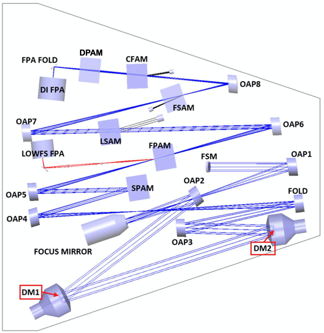
The two other PAMs, located downstream of the coronagraph masks, are the Color Filter Alignment Mechanism (CFAM) and the Dispersion Polarizer Alignment Mechanism (DPAM). The CFAM contains four main bandpass filters: Band 1 is a 10.1% bandwidth111Bandwidth is defined here as the full width at half maximum (FWHM) of the filter transmission profile. centered at 575 nm; Band 2 is a 17.0% bandwidth centered at 660nm; Band 3 is a 16.7% bandwidth at 730nm; and Band 4 is a 11.4% bandwidth at 825nm. Within each full band, there are also several narrower-bandwidth engineering filters used for digging the dark holes. The complete list of CFAM filters and their designed bandpasses is in Table 7, and their final, manufactured properties will be updated in the list of instrument parameters at https://roman.ipac.caltech.edu.
The DPAM contains several standalone lenses as well as two polarization modules (with Wollaston prisms) and two spectroscopy modules (with Amici prisms).[24] The polarization modules are planned for use only in Bands 1 and 4 but could be used without performance degradation in Bands 2 and 3. One spectroscopy module is designed for zero optical deviation and a spectral resolution of 50 at the center wavelength of Band 2, and the other is designed to have those properties at the center of Band 3. The spectroscopy modules could be used in Bands 1 and 4 as well but would have nonzero (but minimal) optical deviation and different spectral resolutions.
2.2 Classes of Mask Configurations
Based on their levels of testing and software support, there are three different classes of mask configurations in the Roman Coronagraph Instrument: primary, supported, and unsupported.
The primary mask configuration will fulfill the instrument’s single, top-level threshold requirement and will therefore receive full, system-level testing on the ground. This top-level requirement is to perform broadband, high-contrast imaging in Band 1 at a small angular separation. It states:
The Roman Coronagraph shall be able to measure, with SNR , the brightness of an astrophysical point source located between 6 and 9 /D from an adjacent star with a VAB magnitude , with a flux ratio . The bandpass shall have a central wavelength nm and a bandwidth %.
To mitigate the programmatic risks associated with demonstrating a high-contrast coronagraph with active wavefront control in space for the first time, this threshold requirement is intentionally set to be easier than the current best estimates of instrument performance, which predict broadband dark holes with raw contrasts in the to range.222Performance predictions for the primary mask configuration and two of the supported ones are available at https://github.com/nasavbailey/DI-flux-ratio-plot and are updated periodically. Note that Band 1 polarimetry is supported on a best-effort basis because it is not tied directly to the top-level requirement.
The three supported mask configurations serve to perform spectroscopy in Bands 2 and 3 as well as wide FOV imaging and polarimetry in Band 4. Being part of the plan but not tied to requirements, these supported mask configurations are included on a best-effort basis. They are receiving component-level hardware support and full software support. The main difference is that they will not receive end-to-end, system-level testing prior to launch.
The NASA Exoplanet Exploration Program (ExEP) is contributing another twenty unsupported mask configurations. The masks for these are being placed in otherwise unused space alongside the supported masks. Other than being installed and aligned, they will not receive any hardware testing or software support as part of the planned technology demonstration. The unsupported mask configurations could be commissioned and used if the instrument is approved for operations after its initial technology demonstration phase.
The unsupported mask configurations are divided into three sub-categories: high-contrast, low-contrast, and calibration. The unsupported high-contrast configurations are largely chosen to fill gaps in the covered parameter space of capabilities; for example, providing narrow FOV imaging to Band 4. The unsupported low-contrast configurations are all simply Lyot coronagraphs that can utilize the instrument’s full field of view. Finally, the unsupported calibration masks are Zernike wavefront sensors (ZWFS) to enable sensitive pupil-plane wavefront measurements, as is desired for the future mission concepts HabEx and LUVOIR.[25]
2.3 Designed Mask Configurations
The complete set of designed mask configurations in the Roman Coronagraph Instrument is shown in Table 1. (Other possible mask configurations are discussed in Section 2.4.) Each row in Table 1 is for a different mask configuration, and the rows are grouped into the different classes of mask configurations (primary, supported, and the three types of unsupported). The columns indicate key optical elements and FOV parameters for each configuration.
Configuration Class Coro. Type Configuration Name Band No. SPAM Pos’n FPAM Pos’ns LSAM Pos’n FSAM Positions Az FOV (deg) IWA (/D) IWA (mas) OWA (/D) OWA (mas) Primary HLC Narrow-FOV 1 1 4-C2R1:9, 4-C3R1:8, 4-C4R7:9 3 R1C1, (R1C3), (R6C6), R5C3, R5C4 360 3.0 150.6 9.7 486.8 Supported SPC Bowtie 2 4 2-R3C2, 2-R4C2, 2-R4C4 5 none, R2C5, R3C1, R3C2, R6C5 130 3.0 172.8 9.1 524.2 SPC Bowtie 3 4 6-R2C2, 6-R4C3, 6-R6C1 5 none, R1C2, R3C1, R3C2, R4C2, R4C6 130 3.0 191.2 9.1 579.8 SPC Wide-FOV 4 2 6-R5C1, 6-R8C1, 6-R8C3 4 none, R1C5, R6C1, R6C2 360 5.9 424.9 20.1 1447.4 Unsupported (High Contrast) SPC Rotated bowtie 2 3 2-R3C1, 2-R3C3, 2-R4C3 1 R4C3, R4C4 130 3.0 172.8 9.1 524.2 SPC Rotated bowtie 3 3 6-R2C3:4, 6-R4C2 1 R2C2, R4C2 130 3.0 191.2 9.1 579.8 SPC Wide-FOV 1 2 2-R1C1:2, 2-R2C1 4 none, R1C5, R6C1, R6C2 360 5.9 296.1 20.1 1008.8 SPC Multi-star 1 5 2-R1C1:2, 2-R2C1 4 R4C1 360 5.9 296.1 20.1 1008.8 SPC Multi-star 4 5 6-R5C1, 6-R8C1, 6-R8C3 4 R1C4, (R4C1) 360 5.9 424.9 20.1 1447.4 HLC Narrow-FOV 2 1 4-C4R1:6, 4-C5R1:8 3 R3C3, R2C3 360 3.0 172.8 9.7 558.8 HLC Narrow-FOV 3 1 3-R5C1:3, 3-R6C1:3, 3-R7C1:2, 3-R8C1 3 R3C4, R4C5, R5C1, R5C2 360 3.0 191.2 9.7 618.1 HLC Narrow-FOV 4 1 3-R2C1:3, 3-R3C1:3, 3-R4C1:3 3 R3C5 360 3.0 216.0 9.1 655.3 Unsupported (Low Contrast) Lyot 0.281” occulter 1, 2 1 4-C2R1:9, 4-C3R1:8, 4-C4R7-9 3, 4 open, any 360 - 140.5 - 3600 Lyot 0.322” occulter 1, 2 1 4-C4R1:6, 4-C5R1:8 3, 4 open, any 360 - 161.1 - 3600 Lyot 0.803” occulter 1, 2 1 4-C1R3:4 3, 4 open, any 360 - 401.5 - 3600 Lyot 0.921” occulter 1, 2 1 4-C1R2 3, 4 open, any 360 - 460.7 - 3600 Lyot 1.807” occulter 1, 2 1 4-C1R1 3, 4 open, any 360 - 903.4 - 3600 Lyot 0.357” occulter 2,3,4 1 3-R5C1:3, 3-R6C1:3, 3-R7C1:2, 3-R8C1 3, 4 open, any 360 - 178.6 - 3600 Lyot 0.403” occulter 2,3,4 1 3-R2C1:3, 3-R3C1:3, 3-R4C1:3 3, 4 open, any 360 - 201.6 - 3600 Lyot 1.020” occulter 2,3,4 1 3-R1C3 3, 4 open, any 360 - 509.8 - 3600 Lyot 1.152” occulter 2,3,4 1 3-R1C1 3, 4 open, any 360 - 576.1 - 3600 Lyot 2.294” occulter 2,3,4 1 3-R1C2 3, 4 open, any 360 - 1147.1 - 3600 Unsupported (Calibration) ZWFS transmissive and reflective 1 1 4-C7R2:8 2 open N/A N/A N/A N/A N/A ZWFS reflective only N/A 1 2-R2C2:4, 6-R4C1, 6-R6C2, 6-R8C2 N/A N/A N/A N/A N/A N/A N/A
Column 4 of Table 1 specifies the bandpasses in which each mask configuration can work. Only the full bandpasses are listed, but each mask configuration also works in all the subbands of the full bands listed; the filter bandwidths are given in Table 7. All of the high-contrast mask configurations work only in their designed bandpass since they require high-order wavefront correction. The unsupported, low-contrast Lyot coronagraphs do not need wavefront correction and are thus spectrally limited only by the anti-reflective (AR) coatings used on the glass focal plane mask (FPM) substrates. The unsupported Zernike wavefront sensor (ZWFS) mask configurations work in reflection with the low-order wavefront sensor (LOWFS), which has its own 128nm-wide filter centered at 575nm. The ZWFS that also works in transmission is designed to work in Band 1 only. It may work in other bands, but that has not been studied.
Columns 5-8 of Table 1 specify PAM mask positions that combine to form that mask configuration. There is only one FPM design per mask configuration; the multiple FPAM locations listed per row are all copies of that given FPM design, which provides redundancy against manufacturing defects and/or dust contamination over the course of the mission. The HLC occulters–when combined with flat DMs–can be used as part of the simple Lyot coronagraphs with inner working angles arcsec. There are only one SPAM mask and one LSAM mask per mode. The low-contrast, traditional Lyot coronagraphs can be used with either Lyot stop that has struts like the telesope pupil (Figs. 11(c) and 11(b)), but most users would probably prefer the one in LSAM position 4 because it provides higher throughput and a sharper PSF at the expense of some contrast.
There are usually several field stops that can work with each mask configuration because the field stops are not used in a diffractive manner to help create the dark hole. Only the field stops designed specifically for each mask configuration are listed in each row of column 8; other desirable pairings are left for the reader to determine based on the field stop specifications provided in Table 6. Of the 31 field stops at the FSAM, 27 are unique. The positions of the four that are duplicates are shown in parentheses in Table 1. All the slit-shaped field stops are intended for use with the spectroscopy modules. The two largest circular field stops (having 1.9-arcsecond and 3.5-arcsecond radii) are primarily intended for use with the Wollaston prisms to eliminate crosstalk between polarization states in the event that the astrophysical source or detectable instrumental scattered light is present at large separations. (The field centers of the two polarization state images are separated by 7.5” on the detector).
The FOV is specified by the azimuthal coverage, inner working angle (IWA), and outer working angle (OWA). All configurations have 360-degree azimuthal FOV except for the bowtie SPCs, which each have coverage. The IWA and OWA are, respectively, the angular separations at which the off-axis throughput ramps up or ramps down to half the maximum value. With the unsupported, traditional Lyot coronagraphs, the IWA column instead lists the occulting spot radius and the OWA column gives the instrument’s full, unvignetted FOV in imaging mode. For the multi-star imaging mask configurations,[26] the field of view is limited to the /D field stop, but that field stop can be placed anywhere within the annular field of view listed in Table 1.
Figure 2 provides a visual representation of the DM surfaces, masks, and stellar PSFs corresponding to all the high-contrast mask configurations listed in Table 1. All the focal plane masks, field stops, and PSFs are shown to scale relative to each other (in terms of ). All pupil masks and DM surfaces are also shown to scale relative to each other (in terms of beam diameter).
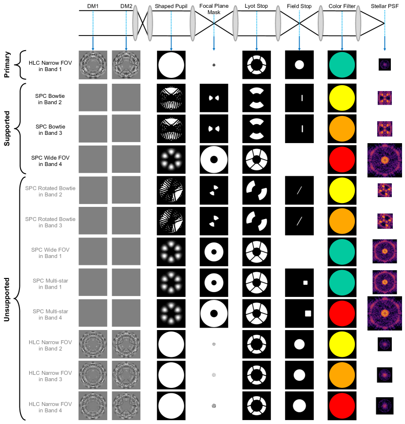
Looking at the combined capabilities of the primary, supported, and unsupported high-contrast mask configurations, much of the possible parameter space is covered with respect to bandpass, field of view, and spectroscopy and polarimetry. The HLC configurations enable imaging and polarimetry at small separations in all four bandpasses. The SPC wide FOV allows those out to larger separations in Bands 1 and 4. For spectroscopy in Bands 2 and 3, the SPC bowtie and SPC rotated bowtie mask configurations cover approximately two-thirds of the available azimuthal FOV at any given time. The Band 2 and 3 HLCs could also be used for spectroscopy, but the SPC bowties are preferred since they are more robust to the observatory jitter and wavefront drift expected over long integration times.
Another unsupported capability in the instrument is multi-star imaging at high contrast. The apodizer for multi-star imaging (at SPAM position 5) is a near-duplicate of the SPC Wide FOV apodizer (at SPAM position 2) except that it contains a square grid of dots to act as a mild diffraction grating. This creates a grid of bright satellite spots in the focal plane that can be used for super-Nyquist wavefront control (SNWC),[27] which is a critical component of multi-star wavefront control (MSWC).[28] Bendek et al.[26] (these proceedings) describe in detail the design and usage cases of the Band 1 and Band 4 multi-star imaging mask configurations in the Roman Coronagraph Instrument.
2.4 Other Possible Mask Configurations
Other than the designed mask configurations listed in Section 2.3, there are many other possible combinations of masks and filters. Some may serve a useful purpose while others are highly discouraged due to poor performance. Either way, all of these other possible mask configurations are unsupported.
2.4.1 Unusable Mask Configurations
In most instances, arbitrary mask combinations would perform worse in most or all cases compared to the mask configurations already specified.
All the focal plane masks are on glass substrates with AR coatings, which restrict the bandpasses in which they can be used. Inside the intended bandpasses the reflectivity of each substrate surface is 0.5%, but outside it is 10%. Substrates in FPAM positions 2 and 4 can be used in Bands 1 and 2, and substrates in FPAM positions 3 and 6 can be used in Bands 2, 3, and 4.
The SPMs were optimized to make dark holes in their specified bandpasses and fields of view, so decent high-contrast dark holes are not possible out of band or with a different FPM. Because the SPMs increase the brightness of speckles outside the dark hole, one would be better off using the SPAM flat mirror instead of any SPM when performing low-contrast imaging over the instrument’s full field of view.
2.4.2 Other, Viable Mask Configurations
As mentioned before, the field stops are not diffractive masks (unlike the SPMs, FPMs, and Lyot stops), so there are many field stops that could work for a given combination of other masks. For any high-contrast HLC cases, the dark hole must be dug in a region at least as large as the field stop to prevent bright speckles from reaching the detector (which could damage the detector and would cause ghosting). Because there are 27 unique field stop shapes, we will not describe all the possible field stop usages.
The only known high-contrast mask configurations not already listed would be formed by swapping out one HLC’s occulter for another. (The previously mentioned limitation from FPM substrate AR coatings still applies, though.) This is possible because the DMs generate most of the contrast for the HLC, and the DM surfaces are changeable on orbit. A slightly smaller IWA could be obtained (at the expense of worse contrast) in Band 4 by using the Band 3 HLC occulter instead. Similarly, the Band 1 HLC occulter could be used in Band 2. In all other cases, though, using a different HLC occulter (or one of the simple Lyot occulters) would result in a larger IWA (but possibly better contrast). The SPC FPMs could also technically be used with DMs instead of an SPM (similar to the HLCs), but we do not believe these hybrid combinations would work as well as the existing mask configurations.
3 Summary and Current Status
In this paper, we have shown all the coronagraph masks that will be included in the Roman Coronagraph Instrument. We listed and described all the designed mask and color filter combinations. There are four high-contrast mask configurations included as part of the mission’s technology demonstration. These configurations accomplish imaging and polarimetry at small angular separations in Band 1, imaging and polarimetry at larger angular separations in Band 4, and imaging and spectroscopy in Bands 2 and 3. The NASA Exoplanet Exploration Program is also contributing a number of unsupported mask configurations that could be used after the initial technology demonstration phase of the mission. These include eight more high-contrast mask configurations to enable multi-star imaging and to complement the FOV and wavelength coverage of the supported mask configurations; several more occulters for low-contrast Lyot coronagraphy; and a Zernike wavefront sensor for high-sensitivity, pupil-plane wavefront estimation.
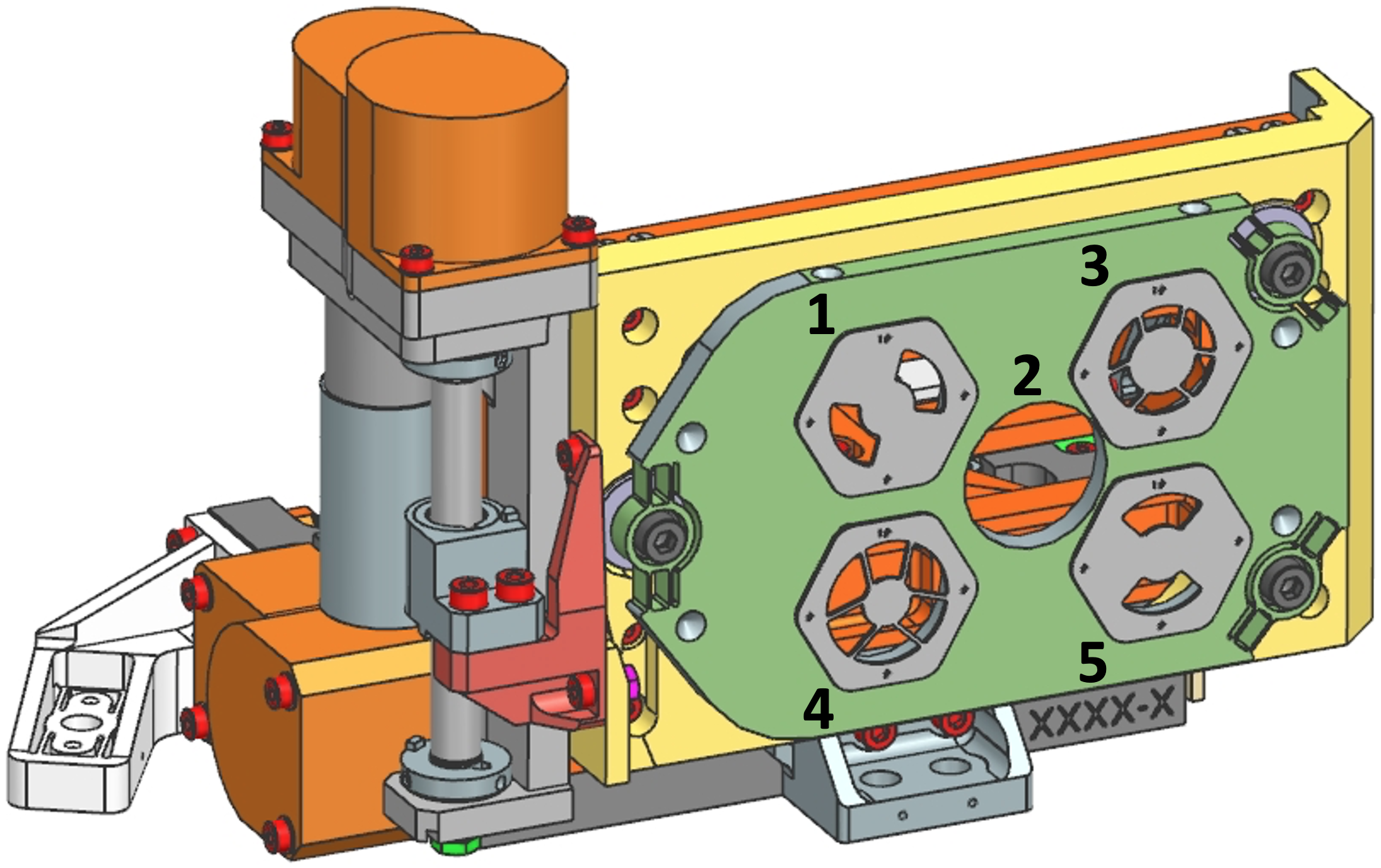
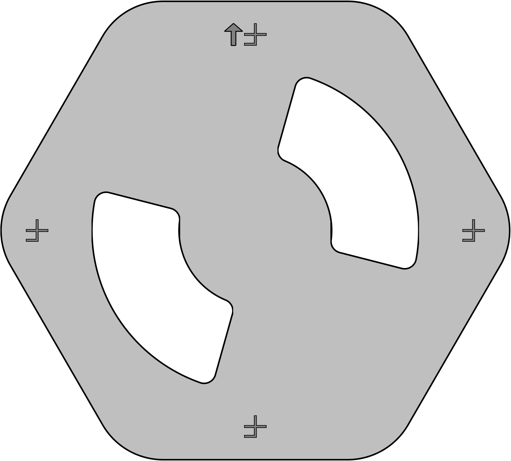
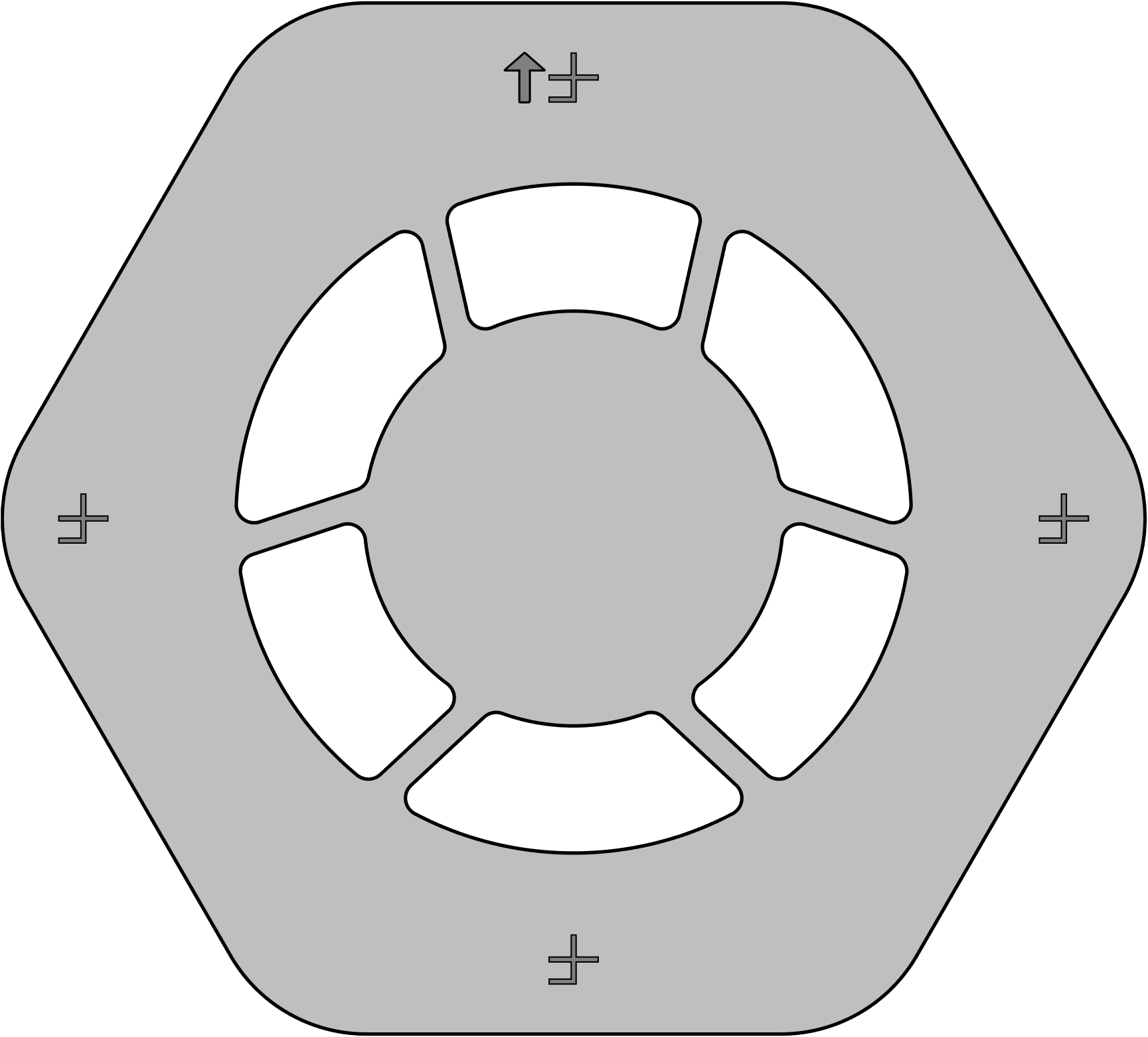
Appendix A Shaped Pupil Masks
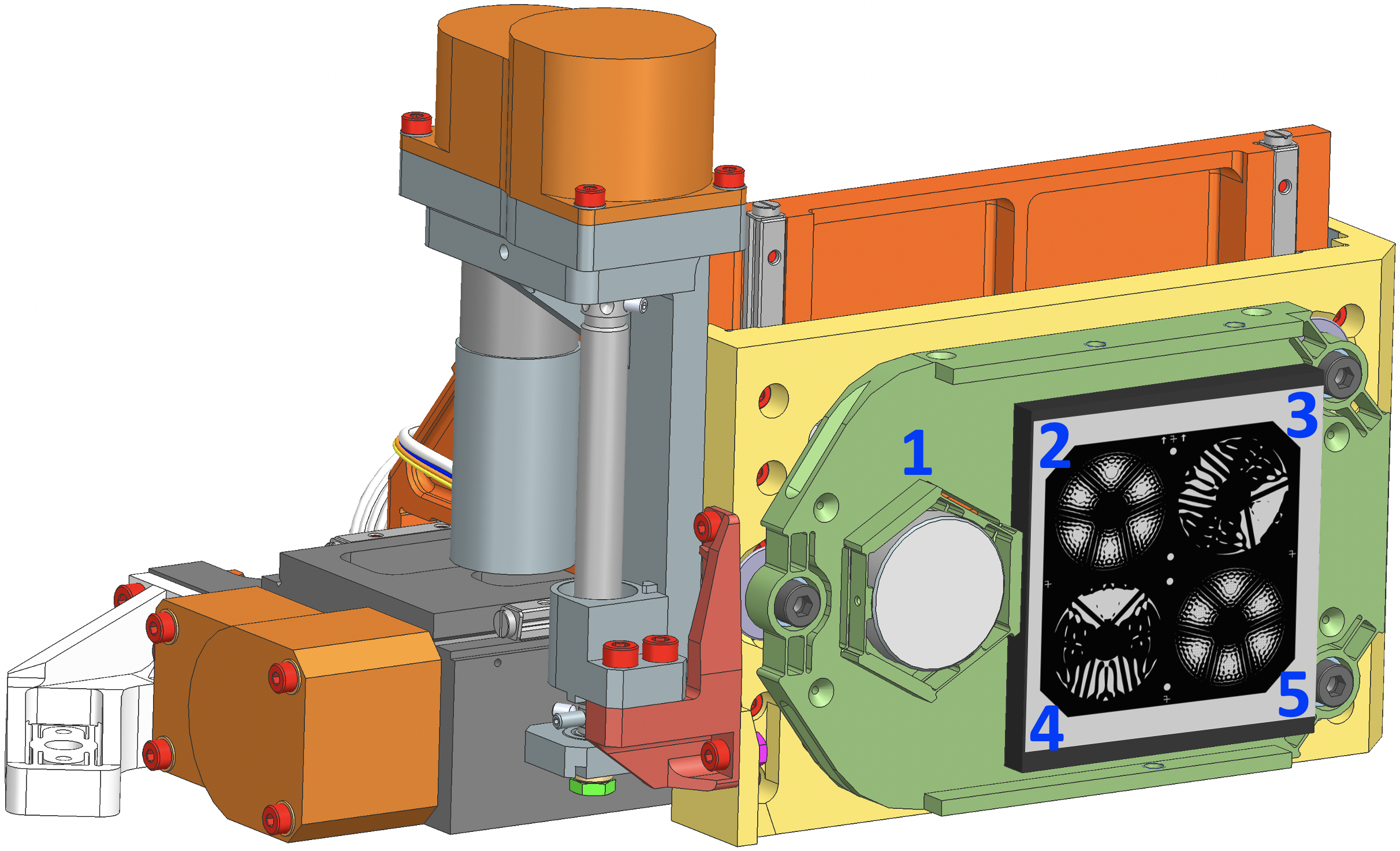
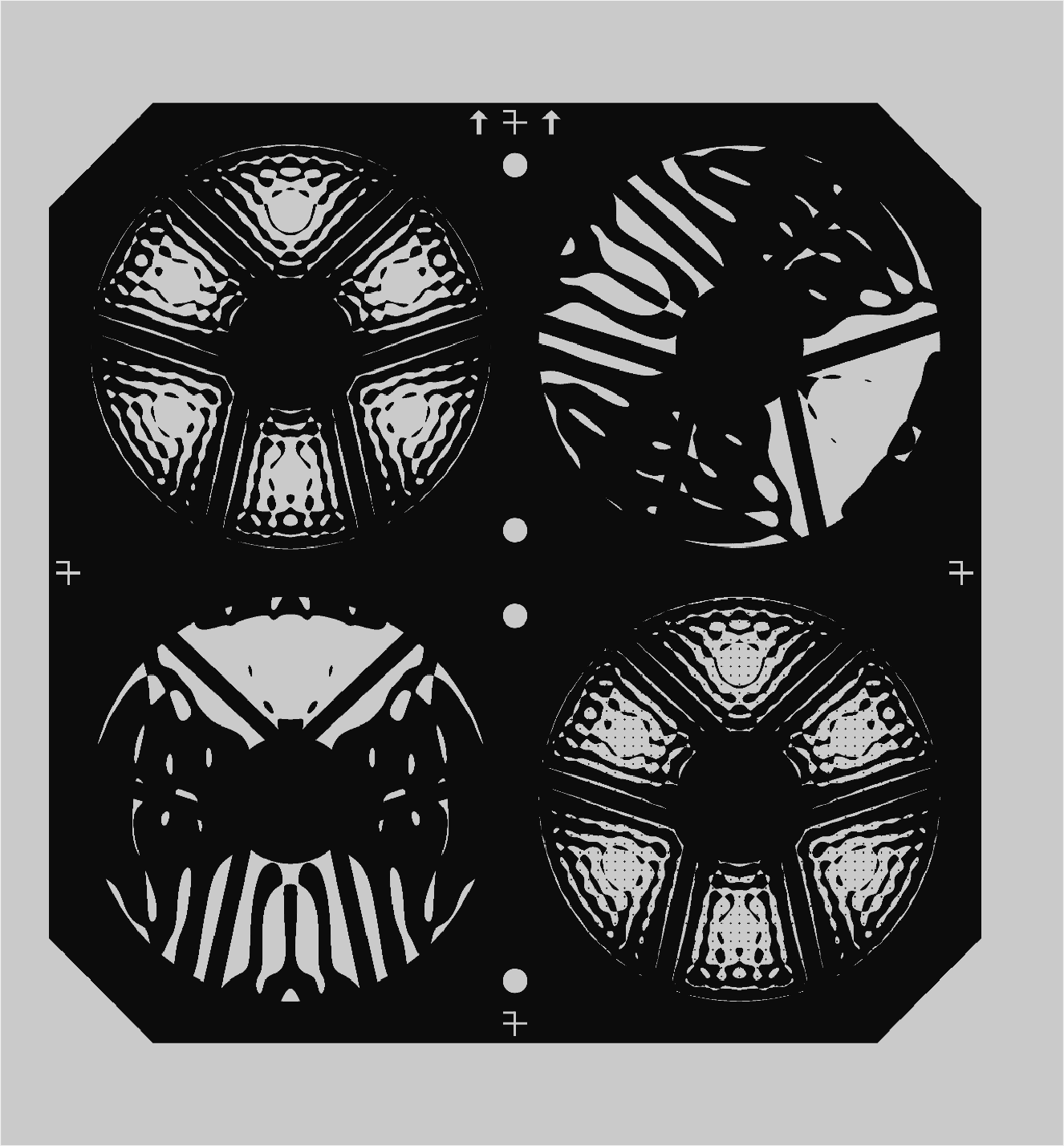
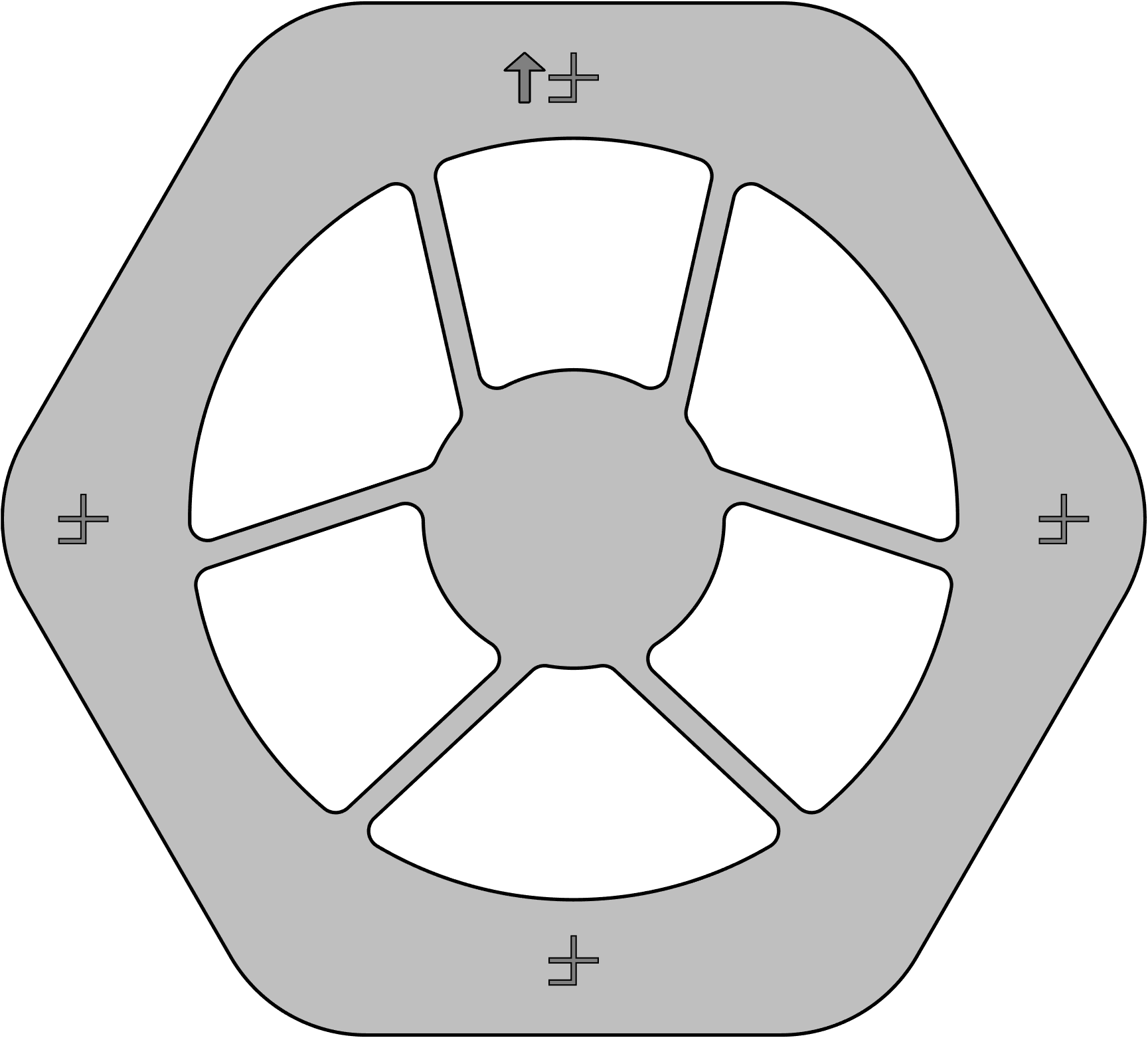
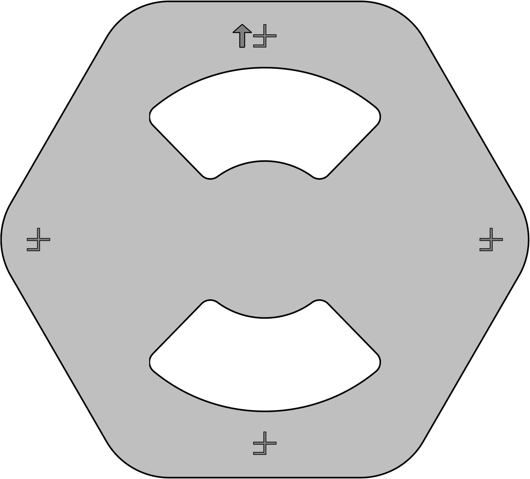
The Shaped Pupil Alignment Mechanism (SPAM), shown in Fig. 3, carries four different shaped pupil masks (SPMs) for the SPCs as well as a standard flat mirror used for the HLCs and calibrations. The HLC flat mirror is in position 1, the SPC wide FOV SPM is in position 2, the SPC rotated bowtie SPM is in position 3, the SPC bowtie SPM is in position 4, and the SPC multi-star imaging SPM is in position 5. A face-on view of the SPM array is provided in Fig. 4.
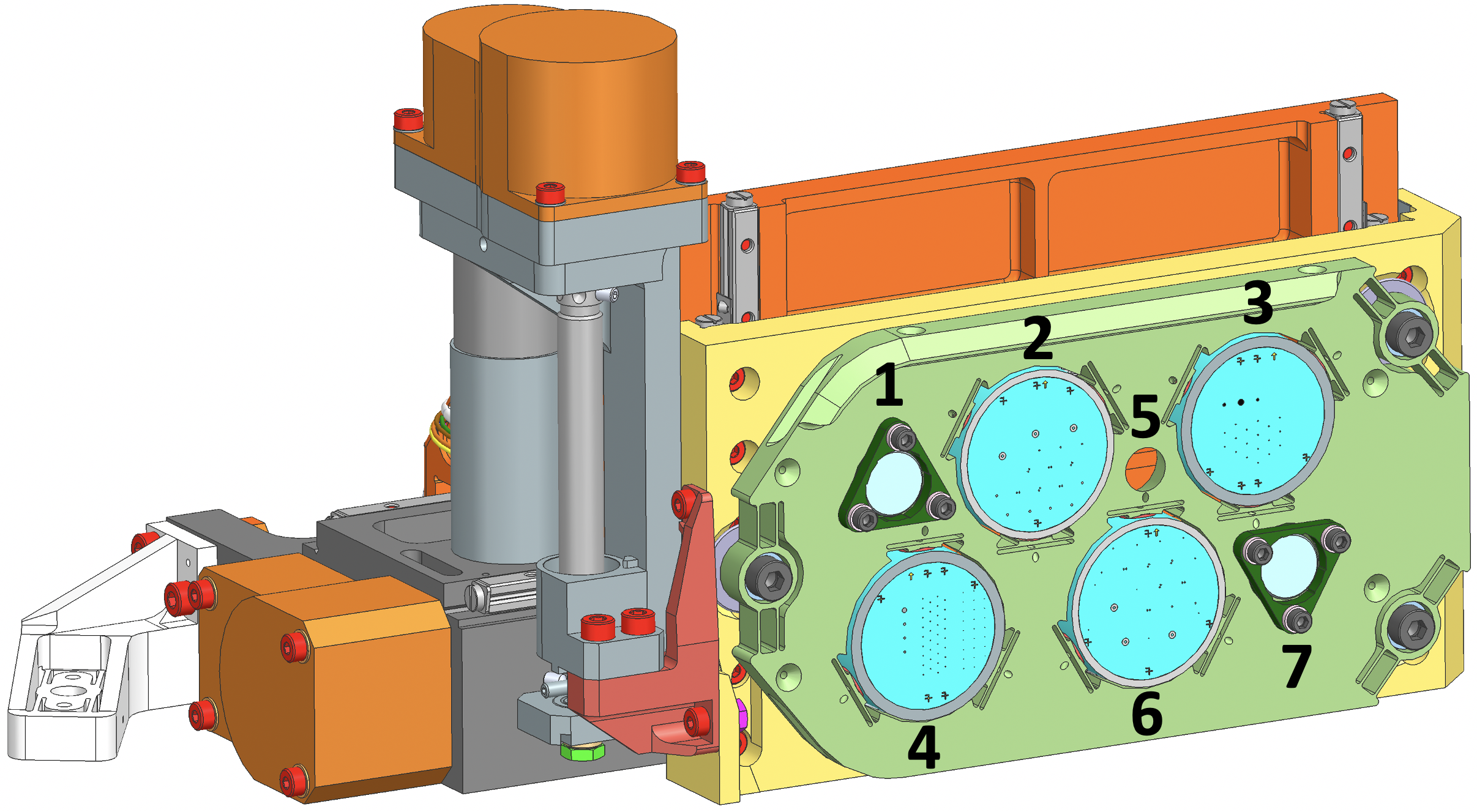
Appendix B Focal Plane Masks
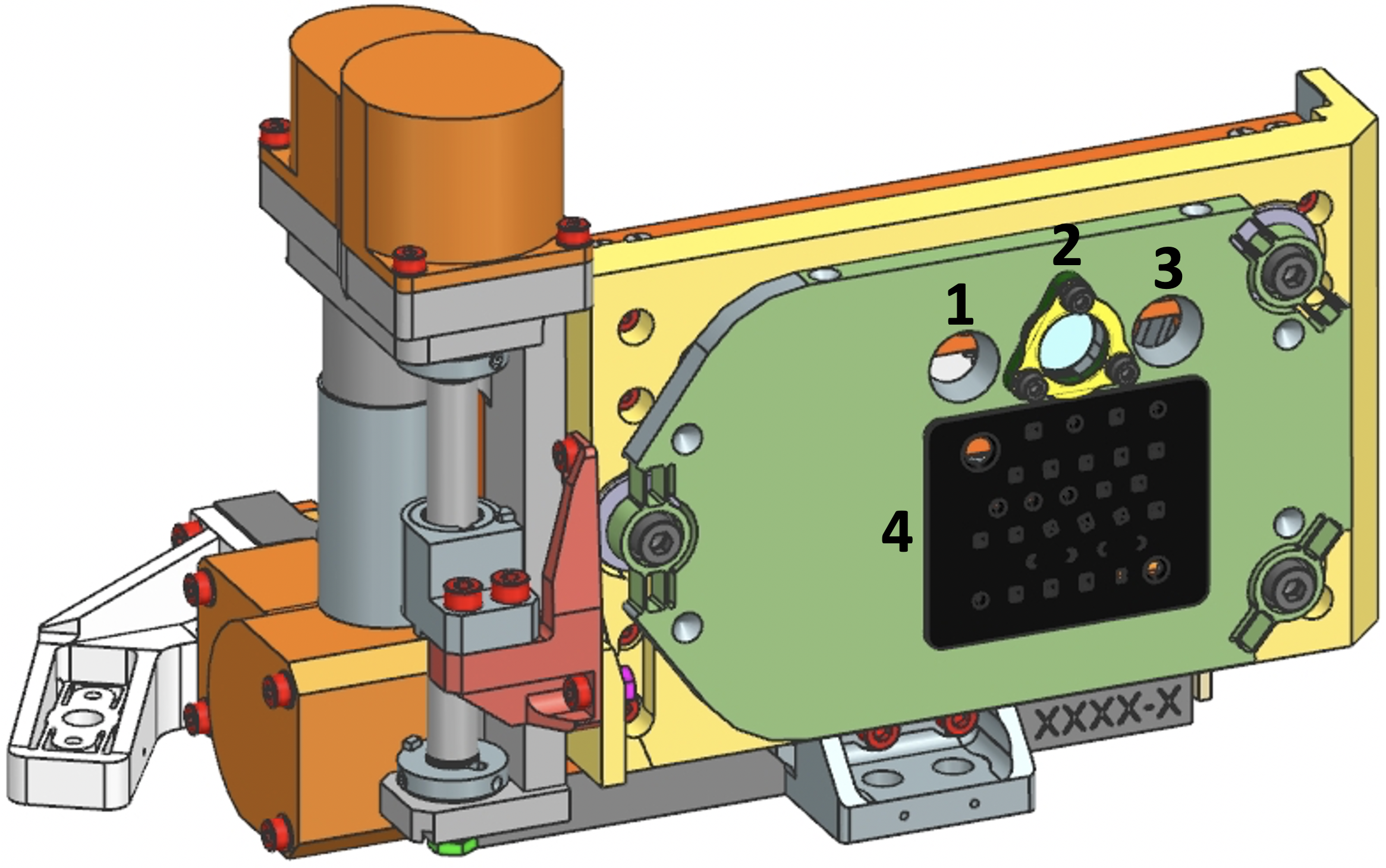
The Focal Plane Alignment Mechanism (FPAM), shown in Fig. 5, has the most masks of any PAM. FPAM positions 2, 3, 4, and 6 each contain a 23mm-diameter, fused silica substrate carrying many FPMs. Position 2 has FPMs for SPCs in Bands 1 and 2, as shown in Fig. 6 and listed in Table 2. Position 6 has FPMs for SPCs in Bands 3 and 4, as shown in Fig. 7 and listed in Table 3. Position 4 has FPMs for HLCs in Bands 1 and 2 as well as ZWFS dimples, as shown in Fig. 8 and listed in Table 4. Position 3 has FPMs for HLCs in Bands 3 and 4, as shown in Fig. 9 and listed in Table 5. Several copies of each FPM design are included in case of fabrication defects or dust contamination. The IWA and OWA for each FPM are given in Table 1.
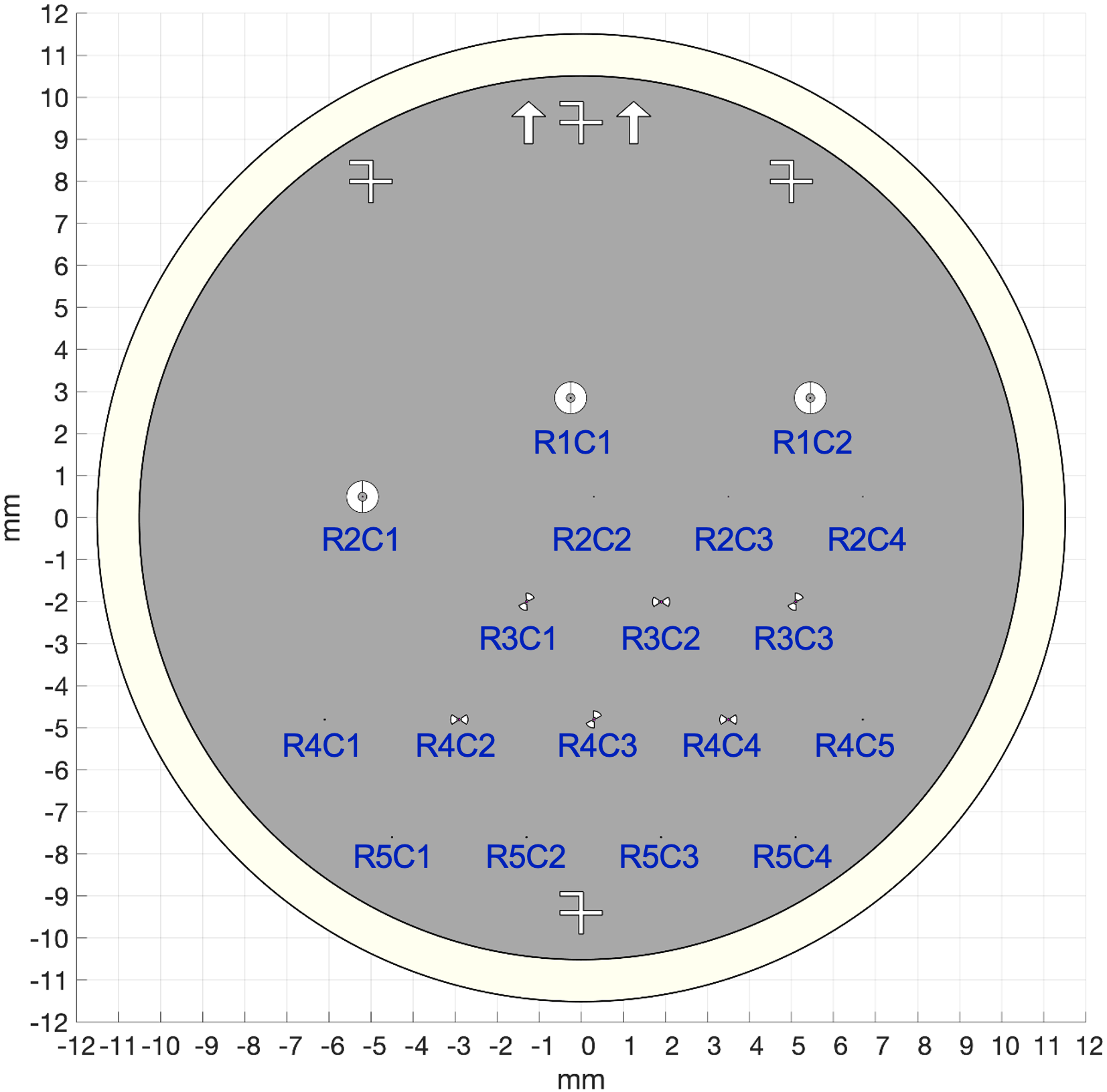
| Mask Name | Band No. | Array Locations |
| SPC Wide-FOV FPM | 1 | R1C1, R1C2, R2C1 |
| SPC Bowtie | 2 | R3C2, R4C2, R4C4 |
| SPC Rotated Bowtie | 2 | R3C1, R3C3, R4C3 |
| ⌀=0.5/D Pinhole | 1 | R4C1, R4C5, R5C1, R5C2, R5C3, R5C4 |
| Reflective-only ZWFS Pimple | (LOWFS) | R2C2, R2C3, R2C4 |
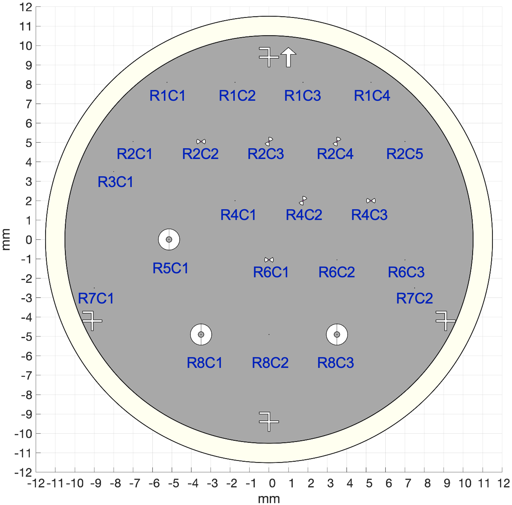
| Mask Name | Band No. | Array Locations |
| SPC Wide-FOV FPM | 4 | R5C1, R8C1, R8C3 |
| SPC Bowtie | 3 | R2C2, R4C3, R6C1 |
| SPC Rotated Bowtie | 3 | R2C3, R2C4, R4C2 |
| ⌀=0.5/D Pinhole | 1 | R2C1, R3C1, R7C1 |
| ⌀=0.5/D Pinhole | 3 | R1C4, R2C5, R6C3, R7C2 |
| ⌀=0.5/D Pinhole | 4 | R1C1, R1C2, R1C3 |
| Reflective-only ZWFS Pimple | (LOWFS) | R4C1, R6C2, R8C2 |
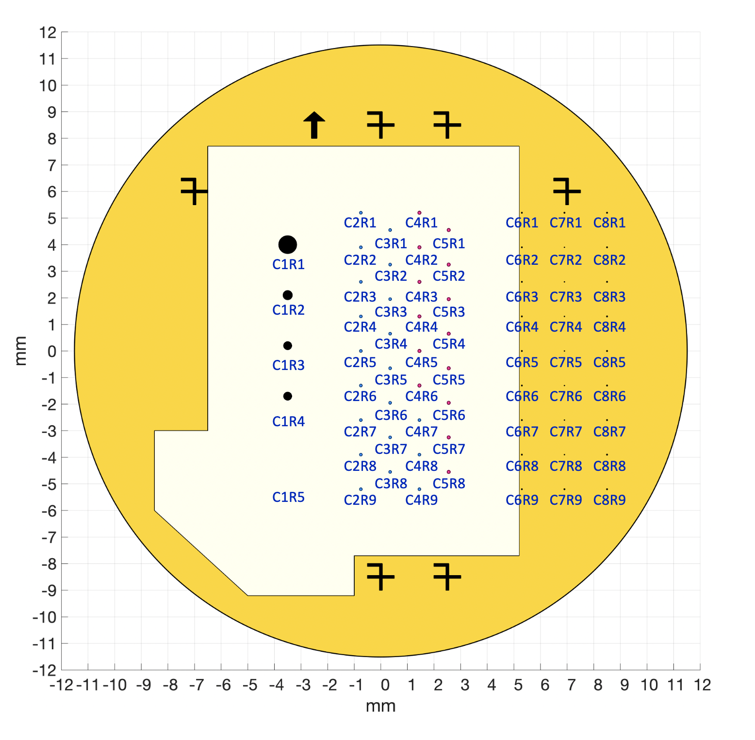
| Mask Name | Band No. | Array Locations |
| ⌀=1.807 arcsec Lyot Occulter | 1, 2 | C1R1 |
| ⌀=0.921 arcsec Lyot Occulter | 1, 2 | C1R2 |
| ⌀=0.803 arcsec Lyot Occulter | 1, 2 | C1R3:4 |
| Open | 1, 2 | C1R5 |
| HLC Occulter | 1 | C2R1:9, C3R1:8, C4R7:9 |
| HLC Occulter | 2 | C4R1:6, C5R1:8 |
| Transmissive-and-reflective ZWFS Dimple | 1 | C7R2:8 |
| ⌀=2/D Alignment Spots for ZWFS | 1 | C6R1:9, C7R1, C7R9, C8R1:9 |
| Mask Name | Band No. | Array Locations |
| ⌀=1.152 arcsec Lyot Occulter | 2, 3, 4 | R1C1 |
| ⌀=2.294 arcsec Lyot Occulter | 2, 3, 4 | R1C2 |
| ⌀=1.020 arcsec Lyot Occulter | 2, 3, 4 | R1C3 |
| Open | 2, 3, 4 | R1C4 |
| HLC Occulter | 4 | R2C1:3, R3C1:3, R4C1:3 |
| HLC Occulter | 3 | R5C1:3, R6C1:3, R7C1:2, R8C1 |
Appendix C Lyot Stop Masks
The Lyot Stop Alignment Mechanism (LSAM), shown in Fig. 10, carries four different lyot stops as well as a though hole used for alignment and calibration. The Lyot stop for the unsupported SPC rotated bowtie is in position 1. The through hole is in the middle at position 2. The Lyot stop for all HLCs is in position 3. The Lyot stop for SPC wide FOV and SPC multi-star imaging is in position 4. The Lyot stop for the supported SPC bowtie is in position 5. Face-on views of the Lyot stops are provided in Fig. 11.
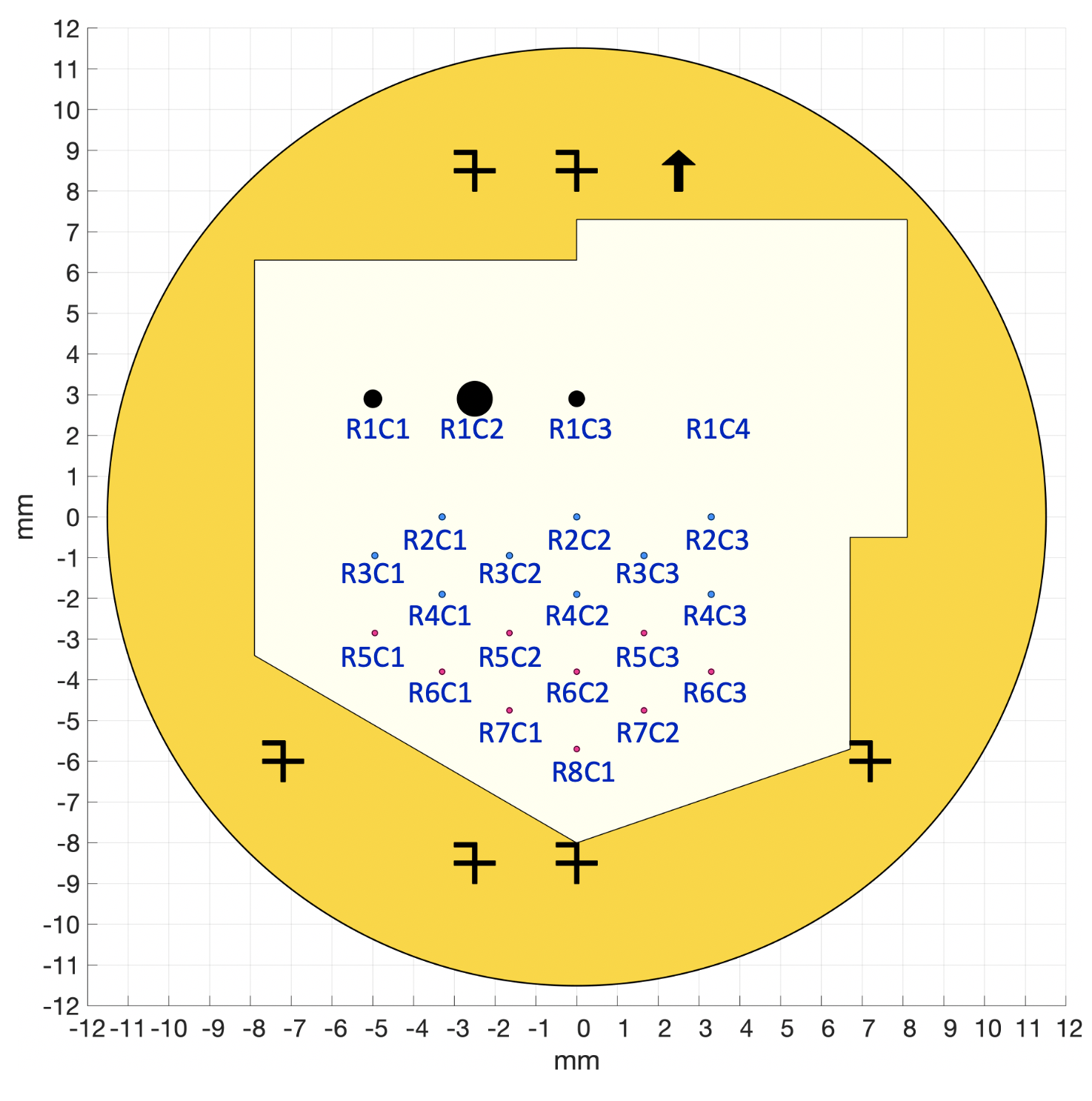
Appendix D Field Stop Masks
The Field Stop Alignment Mechanism (FSAM), shown in Fig. 12, has two open positions (1 and 3), a neutral density filter in position 2, and a silicon wafer carrying all the through-hole field stops in position 4. A face-on view of the substrate with all the field stops is provided in Fig. 13. The specifications for all the field stops are listed in Table 6.
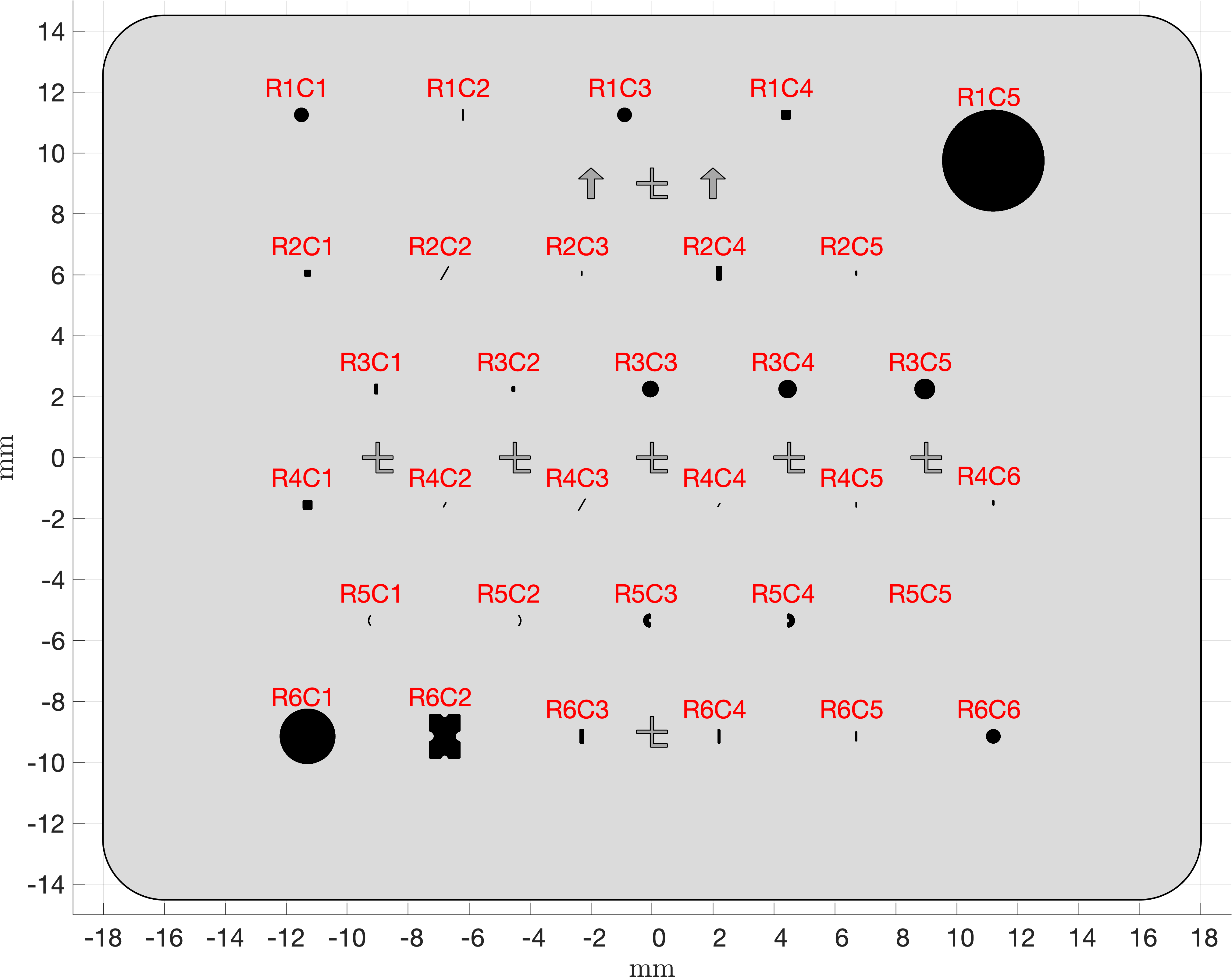
FSAM Position Primary Use Shape Width (m) Width (/D) Width (mas) Height (m) Height (/D) Height (mas) Fillet Radii (micron) 1 Open - - - - - - - - 2 Neutral density (ND) filter - - - - - - - - 3 Open - - - - - - - - 4-R1C1 HLC Band 1 circle 464.34 19.4 974 464.34 19.4 974 N/A 4-R1C2 SPC major-FWHM vertical slit Band 3; tall rect 60.77 2 127 364.84 12 765 30.39 4-R1C3 HLC Band 1 [spare] circle 464.34 19.4 974 464.34 19.4 974 N/A 4-R1C4 Multi-star imaging in Band 4 square 309.07 9 648 309.07 9 648 30 4-R1C5 3.5” radius circular polarimetry field stop circle 3338.28 N/A 7000 3338.28 N/A 7000 N/A 4-R2C1 Multi-star imaging in Band 1 square 215.41 9 452 215.41 9 452 30 4-R2C2 SPC minor-FWHM rotated slit Band 3; tall rect 30.39 1 64 516.58 17 1083 15.19 4-R2C3 HLC FWHM vertical slit Band 2 rect 30.22 1.1 63 164.84 6 346 15.11 4-R2C4 Long slit #3 rect 171.68 N/A 360 476.9 N/A 1000 30 4-R2C5 SPC major-FWHM vertical slit Band 2; short rect 54.95 2 115 164.84 6 346 27.47 4-R3C1 SPC 1st null vertical slit; tall rect 115.72 4 243 347.16 12 728 30 4-R3C2 SPC 1st null vertical slit; short rect 115.72 4 243 173.58 6 364 30 4-R3C3 HLC Band 2 circle 532.98 19.4 1118 532.98 19.4 1118 N/A 4-R3C4 HLC Band 3 circle 589.51 19.4 1236 589.51 19.4 1236 N/A 4-R3C5 HLC Band 4 circle 666.22 19.4 1397 666.22 19.4 1397 N/A 4-R4C1 Multi-star imaging in Band 4 [spare] square 309.07 9 648 309.07 9 648 30 4-R4C2 SPC minor-FWHM rotated slit Band 3; short rect 30.39 1 64 182.32 6 382 15.19 4-R4C3 SPC minor-FWHM rotated slit Band 2; tall rect 27.47 1 58 467.04 17 979 13.74 4-R4C4 SPC minor-FWHM rotated slit Band 2; short rect 27.47 1 58 164.84 6 346 13.74 4-R4C5 HLC FWHM vertical slit Band 3 rect 33.43 1.1 70 182.32 6 382 16.71 4-R4C6 SPC major-FWHM vertical slit Band 3; short rect 60.77 2 127 182.32 6 382 30.39 4-R5C1 HLC FWHM curved slit Band 3 arc 33.43 1.1 70 N/A N/A 16.71 4-R5C2 HLC FWHM curved slit Band 3 (reversed) arc 33.43 1.1 70 N/A N/A 16.71 4-R5C3 Left half HLC Band 1 arc 232.17 9.7 487 464.34 19.4 974 30 4-R5C4 Right half HLC Band 1 arc 232.17 9.7 487 464.34 19.4 974 30 4-R5C5 empty / dark N/A 0 0 0 0 0 0 N/A 4-R6C1 1.9” radius circular polarimetry field stop circle 1812.21 N/A 3800 1812.21 N/A 3800 N/A 4-R6C2 SPC Wide-FOV Halves Bands 1 and 4 puzzle 1024.42 42.8 2148 1469.81 42.8 3082 60 4-R6C3 Long slit #2 rect 143.07 N/A 300 476.9 N/A 1000 30 4-R6C4 Long slit #1 rect 85.84 N/A 180 476.9 N/A 1000 30 4-R6C5 SPC major-FWHM vertical slit Band 2; tall rect 54.95 2 115 329.68 12 691 27.47 4-R6C6 HLC Band 1 [spare] circle 464.34 19.4 974 464.34 19.4 974 N/A
Appendix E Color Filters
All of the color filters included in the Roman Coronagraph are listed in Table 7. The four broadband filters, to be used after the dark hole is dug, are named 1F, 2F, 3F, and 4F. (The F stands for full and is generally omitted for brevity.) All the other filters are subsets of the four larger bandpasses and are used for digging the dark holes in separate subbands. There are three subbands each for Bands 1 and 4, and five each for Bands 2 and 3. Because Bands 2 and 3 overlap, though, subbands 3A and 3B are also used to dig the dark hole in Band 2. The narrowest filters, 2C and 3D, are used for spectroscopy wavelength calibration and line spread function measurements, rather than wavefront correction. Note that 2C also coincides with the H spectral line.
| Filter Name | Center Wavelength (nm) | FWHM (nm) |
|---|---|---|
| 1F | 575 | 58 |
| 1A | 555.8 | 19.2 |
| 1B | 575 | 19.2 |
| 1C | 594.2 | 19.2 |
| 2F | 660 | 112 |
| 2A | 615 | 22 |
| 2B | 638 | 18 |
| 2C | 656.3 | 6.6 |
| 3F | 730 | 122 |
| 3A | 681 | 24 |
| 3B | 704 | 24 |
| 3C | 727 | 20 |
| 3D | 754 | 7.5 |
| 3E | 777.5 | 27 |
| 3G | 752 | 25 |
| 4F | 825 | 94 |
| 4A | 792 | 28 |
| 4B | 825 | 30 |
| 4C | 857 | 30 |
| CLEAR | N/A | N/A |
| ACQ DARK | N/A | N/A |
Acknowledgements.
This work was performed in part at the Jet Propulsion Laboratory, California Institute of Technology, under contract with the National Aeronautics and Space Administration (NASA).References
- [1] Gaudi, B. S., Seager, S., Mennesson, B., Kiessling, A., Warfield, K., Kuan, G., Cahoy, K., Clarke, J. T., Domagal-Goldman, S., Feinberg, L., Guyon, O., Kasdin, J., Mawet, D., Robinson, T., Rogers, L., Scowen, P., Somerville, R., Stapelfeldt, K., Stark, C., Stern, D., Turnbull, M., Martin, S., Alvarez-Salazar, O., Amini, R., Arnold, W., Balasubramanian, B., Baysinger, M., Blais, L., Brooks, T., Calvet, R., Cormarkovic, V., Cox, C., Danner, R., Davis, J., Dorsett, L., Effinger, M., Eng, R., Garcia, J., Gaskin, J., Harris, J., Howe, S., Knight, B., Krist, J., Levine, D., Li, M., Lisman, D., Mandic, M., Marchen, L., Marrese-Reading, C., McGowen, J., Miyaguchi, A., Morgan, R., Nemati, B., Nikzad, S., Nissen, J., Novicki, M., Perrine, T., Redding, D., Richards, M., Rud, M., Scharf, D., Serabyn, G., Shaklan, S., Smith, S., Stahl, M., Stahl, P., Tang, H., Van Buren, D., Villalvazo, J., Warwick, S., Webb, D., Wofford, R., Woo, J., Wood, M., Ziemer, J., Douglas, E., Faramaz, V., Hildebrand t, S., Meshkat, T., Plavchan, P., Ruane, G., and Turner, N., “Habitable Exoplanet Observatory Final Report,” tech. rep., Jet Propulsion Laboratory (August 2019).
- [2] Fischer, D., Peterson, B., Bean, J., Calzetti, D., Dawson, R., Dressing, C., Feinberg, L., France, K., Guyon, O., Harris, W., Marley, M., Meadows, V., Moustakas, L., O’meara, J., Pascucci, I., Postman, M., Pueyo, L., Redding, D., Rigby, J., Roberge, A., Schiminovich, D., Schmidt, B., Stapelfeldt, K., Stark, C., and Tumlinson, J., “LUVOIR Final Report,” tech. rep., NASA (2019).
- [3] Kasdin, N. J., Bailey, V. P., Mennesson, B., Zellem, R. T., Ygouf, M., Rhodes, J., Luchik, T., Zhao, F., Riggs, A. J. E., Seo, B.-J., Krist, J., Kern, B., Tang, H., Nemati, B., Groff, T. D., Zimmerman, N., Macintosh, B., Turnbull, M., Debes, J., Douglas, E. S., and Lupu, R. E., “The Nancy Grace Roman Space Telescope Coronagraph Instrument (CGI) technology demonstration,” in [Space Telescopes and Instrumentation 2020: Optical, Infrared, and Millimeter Wave ], Lystrup, M., Perrin, M. D., Batalha, N., Siegler, N., and Tong, E. C., eds., 11443, 300 – 313, International Society for Optics and Photonics, SPIE (2020).
- [4] Poberezhskiy, I., Luchik, T., Zhao, F., Frerking, M., Basinger, S., Cady, E., Colavita, M. M., Creager, B., Fathpour, N., Goullioud, R., Groff, T., Morrissey, P., Kempenaar, J., Kern, B., Koch, T., Krist, J., Mok, F., Muliere, D., Nemati, B., Riggs, A., Seo, B.-J., Shi, F., Shreckengost, B., Steeves, J., and Tang, H., “Roman space telescope coronagraph: engineering design and operating concept,” in [Space Telescopes and Instrumentation 2020: Optical, Infrared, and Millimeter Wave ], Lystrup, M., Perrin, M. D., Batalha, N., Siegler, N., and Tong, E. C., eds., 11443, 314 – 335, International Society for Optics and Photonics, SPIE (2021).
- [5] Mennesson, B., Bailey, V. P., Zellem, R. T., et al., “The Roman Space Telescope coronagraph technology demonstration: current status and relevance to future missions,” in [Proc. SPIE ], 11823(11823-79) (2021).
- [6] Cady, E., Prada, C. M., An, X., Balasubramanian, K., Diaz, R., Kasdin, N. J., Kern, B., Kuhnert, A., Nemati, B., Poberezhskiy, I., Riggs, A. J. E., Zimmer, R., and Zimmerman, N., “Demonstration of high contrast with an obscured aperture with the WFIRST-AFTA shaped pupil coronagraph,” J. Astron. Telesc. Instrum. Syst 2(1), 011004 (2015).
- [7] Seo, B.-J., Gordon, B., Kern, B., Kuhnert, A., Moody, D., Muller, R., Poberezhskiy, I., Trauger, J., and Wilson, D., “Hybrid Lyot coronagraph for wide-field infrared survey telescope-astrophysics focused telescope assets: occulter fabrication and high contrast narrowband testbed demonstration,” J. Astron. Telesc. Instrum. Syst 2(1), 011019 (2016).
- [8] Cady, E. et al., “Shaped pupil coronagraphy for WFIRST: high-contrast broadband testbed demonstration,” in [Proc. SPIE ], 10400, 104000E (2017).
- [9] Marx, D., Cady, E., Riggs, A. J. E., Prada, C., Kern, B., Seo, B.-J., and Shi, F., “Shaped pupil coronagraph: disk science mask experimental verification and testing,” in [Space Telescopes and Instrumentation 2018: Optical, Infrared, and Millimeter Wave ], Lystrup, M., MacEwen, H. A., Fazio, G. G., Batalha, N., Siegler, N., and Tong, E. C., eds., 10698, 446 – 454, International Society for Optics and Photonics, SPIE (2018).
- [10] Seo, B.-J., Cady, E., et al., “Hybrid Lyot coronagraph for WFIRST: high-contrast broadband testbed demonstration,” in [Proc. SPIE ], 10400, 15 (2017).
- [11] Seo, B.-J., Shi, F., et al., “Hybrid Lyot coronagraph for WFIRST: high contrast testbed demonstration in flight-like low flux environment,” in [Proc. SPIE ], 10698 (2018).
- [12] Shi, F., Balasubramanian, K., Hein, R., Lam, R., Moore, D., Moore, J., Patterson, K., Poberezhskiy, I., Shields, J., Sidick, E., Tang, H., Truong, T., Wallace, J. K., Wang, X., and Wilson, D., “Low-order wavefront sensing and control for WFIRST-AFTA coronagraph,” J. Astron. Telesc. Instrum. Syst 2(1), 011021 (2016).
- [13] Shi, F., Cady, E., Seo, B.-J., An, X., Balasubramanian, K., Kern, B., Lam, R., Marx, D., Moody, D., Prada, C. M., Patterson, K., Poberezhskiy, I., Shields, J., Sidick, E., Tang, H., Trauger, J., Truong, T., White, V., Wilson, D., and Zhou, H., “Dynamic testbed demonstration of WFIRST coronagraph low order wavefront sensing and control (LOWFS/C),” in [Techniques and Instrumentation for Detection of Exoplanets VIII ], Shaklan, S., ed., 10400, 74 – 90, International Society for Optics and Photonics, SPIE (2017).
- [14] Shi, F., Shields, J., Truong, T., Seo, B.-J., Fregoso, F., Kern, B., Marx, D., Patterson, K., Prada, C. M., Shaw, J., and Shelton, C., “WFIRST low order wavefront sensing and control (LOWFS/C) performance on line-of-sight disturbances from multiple reaction wheels,” in [Techniques and Instrumentation for Detection of Exoplanets IX ], Shaklan, S. B., ed., 11117, 170 – 178, International Society for Optics and Photonics, SPIE (2019).
- [15] Harding, L. K., Demers, R. T., Hoenk, M., Peddada, P., Nemati, B., Cherng, M., Michaels, D., Neat, L. S., Loc, A., Bush, N., Hall, D., Murray, N., Gow, J., Burgon, R., Holland, A., Reinheimer, A., Jorden, P. R., and Jordan, D., “Technology advancement of the CCD201-20 EMCCD for the WFIRST coronagraph instrument: sensor characterization and radiation damage,” J. Astron. Telesc. Instrum. Syst 2(1), 011007 (2015).
- [16] Moody, D. and Trauger, J., “Hybrid Lyot coronagraph masks and wavefront control for improved spectral bandwidth and throughput,” in [Proc. SPIE ], 6693, 66931I, SPIE (2007).
- [17] Trauger, J., Moody, D., Gordon, B., Krist, J., and Mawet, D., “A hybrid lyot coronagraph for the direct imaging and spectroscopy of exoplanet systems: recent results and prospects,” in [Proc. SPIE ], 8151, 81510G, SPIE (2011).
- [18] Trauger, J., Moody, D., Krist, J., and Gordon, B., “Hybrid Lyot coronagraph for WFIRST-AFTA: coronagraph design and performance metrics,” J. Astron. Telesc. Instrum. Syst 2(1), 011013 (2016).
- [19] Carlotti, A., Vanderbei, R., and Kasdin, N., “Optimal pupil apodizations of arbitrary apertures for high-contrast imaging,” Opt. Express 19(27), 26796–26809 (2011).
- [20] Vanderbei, R., “Fast Fourier optimization: Sparsity matters,” Math. Prog. Comp. , 1–17 (2012).
- [21] Zimmerman, N. T., Riggs, A. J. E., Jeremy Kasdin, N., Carlotti, A., and Vanderbei, R. J., “Shaped pupil Lyot coronagraphs: high-contrast solutions for restricted focal planes,” J. Astron. Telesc. Instrum. Syst 2(1), 011012 (2016).
- [22] Riggs, A. J. E., Zimmerman, N. T., Nemati, B., and Krist, J. E., “Shaped pupil coronagraph design improvements for the WFIRST Coronagraph Instrument,” in [Proc. SPIE ], 10400, 104000O (2017).
- [23] Riggs, A. E., Ruane, G., and Kern, B. D., “Directly constraining low-order aberration sensitivities in the WFIRST coronagraph design,” in [Techniques and Instrumentation for Detection of Exoplanets IX ], Shaklan, S. B., ed., 11117, 136 – 149, International Society for Optics and Photonics, SPIE (2019).
- [24] Groff, T. D., Zimmerman, N. T., Subedi, H. B., Rizzo, M. J., Titus, J., Lyons, J., Bell, D., Gaylin, S., Gao, G., Pasquale, B., Nicolaeff, N., Tamura, M., and Shi, F., “Roman Space Telescope CGI: prism and polarizer characterization modes,” in [Space Telescopes and Instrumentation 2020: Optical, Infrared, and Millimeter Wave ], Lystrup, M., Perrin, M. D., Batalha, N., Siegler, N., and Tong, E. C., eds., 11443, 640 – 648, International Society for Optics and Photonics, SPIE (2021).
- [25] Ruane, G. J., Wallace, J. K., Steeves, J. B., Prada, C. M., Seo, B.-J., Bendek, E. A., Coker, C. T., Chen, P., Crill, B. P., Jewell, J. B., Kern, B. D., Marx, D. S., Poon, P. K., Redding, D. C., Riggs, A. E., Siegler, N., and Zimmer, R. P., “Wavefront sensing and control in space-based coronagraph instruments using Zernike’s phase-contrast method,” J. Astron. Telesc. Instrum. Syst. 6(4), 1 – 26 (2020).
- [26] Bendek, E., Belikov, R., Sirbu, D., Riggs, A. J. E., Ruane, G., and Pluzhnik, E. A., “Enabling binary stars high-contrast imaging on the Roman Space Telescope Coronagraph Instrument,” in [Proc. SPIE ], 11823(11823-54) (2021).
- [27] Thomas, S., Belikov, R., and Bendek, E., “TECHNIQUES FOR HIGH-CONTRAST IMAGING IN MULTI-STAR SYSTEMS. i. SUPER-NYQUIST WAVEFRONT CONTROL,” Astrophys. J. 810, 81 (sep 2015).
- [28] Sirbu, D., Thomas, S., Belikov, R., and Bendek, E., “Techniques for high-contrast imaging in multi-star systems. II. multi-star wavefront control,” Astrophys. J. 849, 142 (nov 2017).
- [29] Balasubramanian, K., White, V., Yee, K., Echternach, P., Muller, R., Dickie, M., Cady, E., Prada, C. M., Ryan, D., Poberezhskiy, I., Kern, B., Zhou, H., Krist, J., Nemati, B., Eldorado Riggs, A. J., Zimmerman, N. T., and Kasdin, N. J., “WFIRST-AFTA coronagraph shaped pupil masks: design, fabrication, and characterization,” J. Astron. Telesc. Instrum. Syst 2(1), 011005 (2015).
- [30] Balasubramanian, K., Riggs, A. J. E., Cady, E., White, V., Yee, K., Wilson, D., Echternach, P., Muller, R., Prada, C. M., Seo, B.-J., Shi, F., Ryan, D., Fregoso, S., Metzman, J., and Wilson, R. C., “Fabrication of coronagraph masks and laboratory scale star-shade masks: characteristics, defects, and performance,” in [Techniques and Instrumentation for Detection of Exoplanets VIII ], Shaklan, S., ed., 10400, 74 – 89, International Society for Optics and Photonics, SPIE (2017).
- [31] Balasubramanian, K., Seo, B.-J., Patterson, K., Mejia Prada, C., Riggs, A. E., Zhou, H., Moody, D., Cady, E., White, V., Yee, K., Muller, R., Echternach, P., Greer, F., and Wilson, D., “Critical characteristics of coronagraph masks influencing high contrast performance,” in [Proc. SPIE ], 11117 (2019).