A metamaterial with applications in broad band antennas used in radio astronomy and satellite communications
Abstract
Electromagnetic metamaterials at microwave frequencies are well established in industry and research. Recent work has shown how a specific kind of metallic metamaterial can contribute towards improving the performance of the feedhorn antennas used in radio astronomy and satellite telecommunications. In this article, we discuss an innovative type of meta-ring of remarkable manufacturability, able to improve the state of the art in these fields. A pioneering meta-horn antenna formed of meta-rings is then fabricated and characterized in the laboratory. It shows an excellent feature on an octave bandwidth, especially in terms of cross-polarization, a key figure of merit in both radio astronomy and telecommunications, and also side-lobe level, return-loss and gain.
1 Introduction
Electromagnetic metamaterials at microwave frequencies are well established in both industry and research (e.g., [1], [2], [3] and [4]). They are distinguished by their electromagnetic properties, which differ from those given by their basic constituent as the consequence of a smart structure. Recent research led us to think that electromagnetic metamaterials can also be used in the manufacture of antennas for satellite communications [5] [6] [7] [8] [9]. Horn-antennas made of metamaterials, or meta-horns, could give a significant improvement to the state of the art in the field of feedhorn antennas with low cross-polarization and sidelobe levels, a technology that has been static for several decades owing to insurmountable limitations in the bandwidth of corrugated feedhorns [10]. Unfortunately, the fabrication of metamaterial structures is challenging due to their geometric complexity and (frequency-dependent) reduced size required for applications in satellite communications and astronomy in the microwave range. This is probably the reason why this technology is not fully implanted nowadays in either radio astronomy or telecommunications.
In [7] we theorized on cross-polarization of feed-horn antennas and we presented the topology of a new metamaterial able to surpass some limitations of corrugated horns. In [11] we explored the manufacturability of such a metamaterial using different techniques. In this work, we present a prototype of a meta-horn made of this metamaterial, which shows promising results. Success in this research could provide important benefits for astronomy, since the sensitivity of broad band receivers scales as , i.e., the square root of bandwidth obtained in comparison with a classical corrugated horn-antenna [12]. Meta-horns could provide excellent performance on very wide frequency ranges not reachable with classic corrugated horn-antennas. Thanks to the ability to span multiple bands typically covered by several devices, they could relax the complexity of wide-band receivers in terms of hardware and associated costs. Moreover, current satellites tend to transmit through the Ka and Ku bands, which are too wide to be covered with a standard corrugated horn antenna. The novel technique presented in this work can cover both bands simultaneously with a single receiver in the frequency range 10–30 GHz. This corresponds to , where is the bandwidth factor, i.e. the ratio between the maximal and minimal frequency in a band. The theoretical limit for the meta-horn presented here is around ; however, we aimed at a lower value to make our objective easier to achieve. Note that this is still a good improvement if compared to standard antennas, which typically yield , commonly referred as a 40% or 1.4:1 [10].
This article is structured as follows. In Sec. 2 we introduce the fundamentals of reflector antennas and metamaterials relevant for this article. Section 3 presents a novel feedhorn antenna made of a new class of metamaterial, or meta-ring, and its experimental demonstration. Finally, in Sec. 4 conclusions and future directions are discussed.
2 Theoretical fundamentals
The field generated at the optical focus of a paraboloid with large focal length can be divided into two polarizations: a P-polarization, or also called transverse magnetic (TM) component, polarized in the plane of incidence, with its electric (E) component oriented normally to the plane on which the beam is projected, and a S-polarization, or transverse electric (TE) pattern, polarized normally to the plane of incidence [13]. The feedhorn which transmits both the azimuthal and longitudinal components with null cross-polarization222Cross-polarization could be qualitatively understood as crosstalk between the TE and TM modes through the antenna reducing the purity of the transmitted signal [14]. must have inner surfaces satisfying the following expression:
| (2.1) |
where is the surface impedance for both polarizations (or, equivalently, spatial directions from the surface) and is the impedance of the vacuum. The relation in (2.1) is known as the balanced hybrid-mode condition and guarantees that the HE11 mode is fundamental and of a high cross-polarization purity. In [13] it was suggested that a radially corrugated cylindrical waveguide can be used in order to support the hybrid-mode condition over a limited band. Other authors give a more in-depth treatment of the corrugated feedhorn technology [10], which efficiently exploits modes hybridization to push the bandwidth factor to around 1.4:1.
To obtain an even wider bandwidth, 2:1 and beyond, while preserving low cross-polarization levels, we designed a new metamaterial with a surface impedance equal to the critical value, similar to [5]. It is well known that the reflection coefficient for a wave travelling through vacuum and perpendicularly to a plane surface is
| (2.2) |
where represents the forward incident wave and represents the backward reflected wave, is the impedance of the (plane) surface and is the impedance of the vacuum. This is represented in Fig. 1.
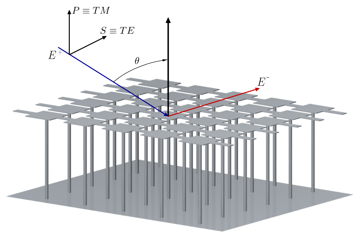
Therefore, it is possible to obtain expressions for TE and TM modes being reflected by a surface with characteristic impedance. The effective free-space impedance in this geometry is a function of the incidence angle , which is arbitrary. For -polarized modes
| (2.3) |
and for -polarized modes
| (2.4) |
From equations (2.2), (2.3) and (2.4), we can derive the expression of the surface impedance for the reflected -modes
| (2.5) |
and the reflected -modes
| (2.6) |
Finite element method (FEM) 3D electromagnetic simulations333Running on CST Studio Suite or similar softwares. allow one to estimate the characteristic impedance of each mode, once the reflection coefficients have been calculated. The values are plugged in (2.1) to verify if the meta-surface fulfils the hybrid-mode condition.
In the simulations, a plane wave is reflected on a metamaterial containing an E-field probe over its surface. By comparing the E-field probed in the same position with and without the presence of the metamaterial under test, we can subtract the incoming and reflected signals to obtain the reflection coefficient and surface impedance for each or polarization from equations (2.6) and (2.5) (more details are given in [5], [6], [7], [11]).
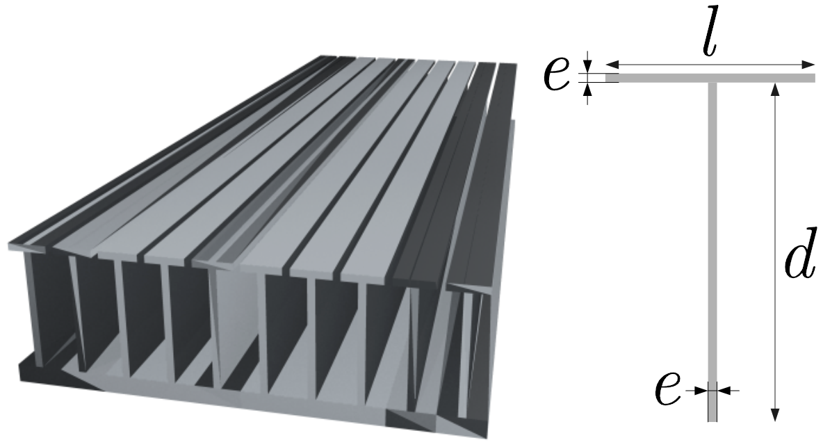
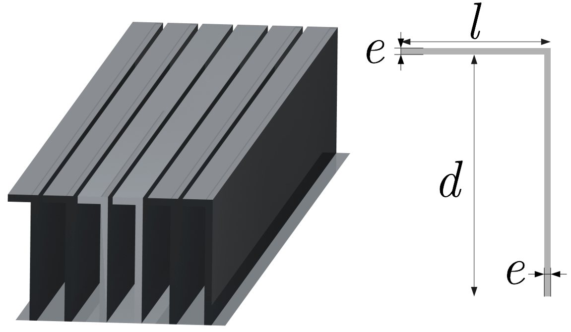
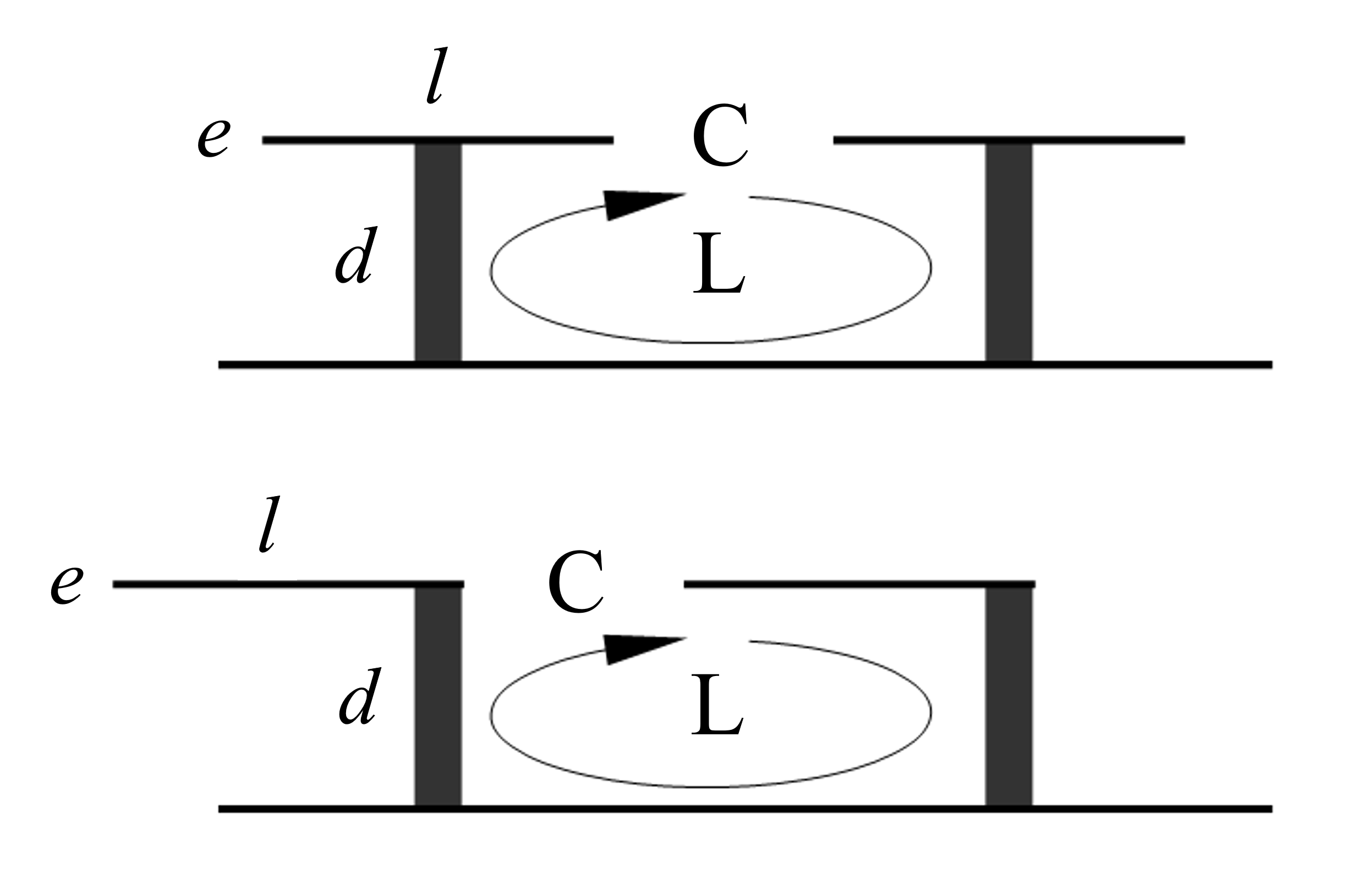
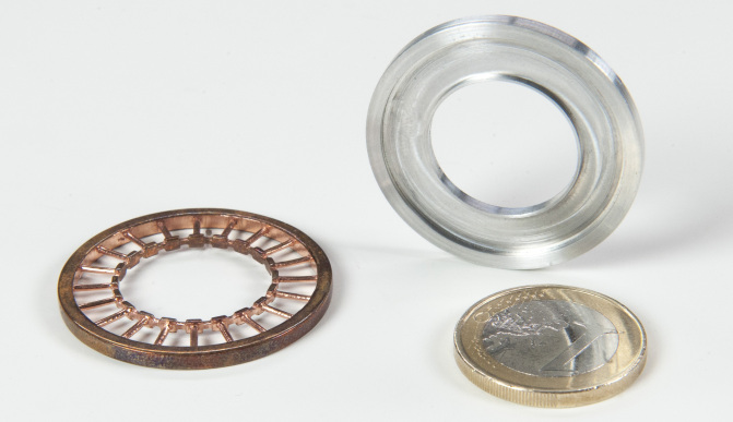
Left and center panels of Fig. 2 show two simple structures of a novel 3D metamaterial, which are equivalent from an electromagnetic perspective, as explained in the right panel of the same figure. Their concept relies on a simplification of the structure shown in Fig. 1, which allows for an easy manufacturability. The simplified design not only guarantees performance comparable to that obtained for the model in Fig. 1, but also extends it to an even wider operating bandwidth, as discussed in [11]. It is convenient to remark that the aim of these simulations is to design the inner surface of a horn-antenna, made up of tens or hundreds of rings based on the design in Fig. 2 joined together. Fig. 3 shows a first sample of a meta-ring. The technique to manufacture the meta-horn will be adequately discussed later in this work, and a proof-of-concept prototype will be presented.
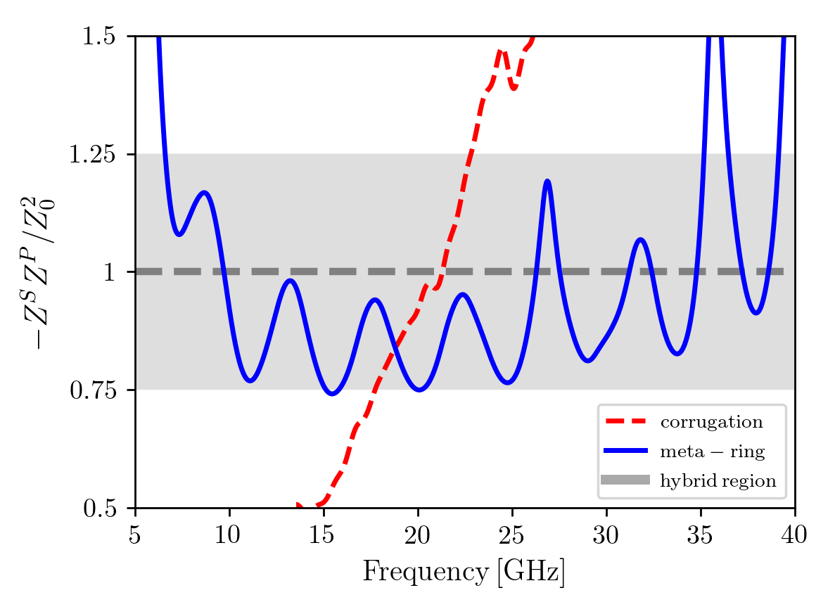
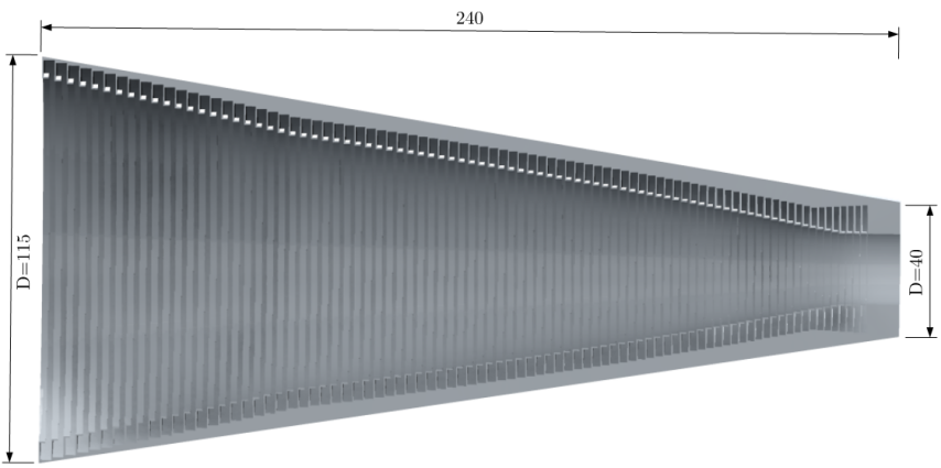
From Eq. 2.1, it follows that a metamaterial satisfies the hybrid-mode condition when is exactly 1. We expect that values of in the vicinity of 1 yields moderate cross polarization scattering.444Later we discuss how different features can also influence the levels of cross-polarization. Therefore, we can empirically define a “hybrid region”, which is shaded in gray in Fig. 4. The solid blue line corresponds to the top-plated or “inverted L” metamaterial shown in Fig. 2. The acceptable behaviour in terms of cross-polarization is found within the 6.5–35 GHz band, i.e. a 5:1 bandwidth factor. The dashed red line represents the case of a corrugated wall with similar dimensions. Note that the product of normalized impedances has a steep slope, which leads to a bandwidth factor of approximately 1.4:1 or 40% of the band limited between 17–24 GHz, as expected. The error in the simulations, performed in the time domain, propagates when the results are converted to the frequency domain by Fourier transform. Together with a non-negligible plate thickness compared to the wavelength, of the order of , this can explain the observed frequency shift with respect to an idealized model, where a short circuit is expected at the top of the groove around 23 GHz for a depth of 6.5 mm. We found also that it is not possible to improve the performance of the corrugated wall in terms of the hybrid condition. A different geometry results in a shifted band but the slope of always remains large, so the hybrid bandwidth is always about 40% or lower. In the next section we present a meta-horn based on the “inverted L” meta-ring topology shown in Fig. 2 (center panel), fabricated in a standard workshop by traditional techniques [11]. Its layout, resulting in a 240 mm long dual-tapered profile with a 103.1 mm aperture diameter, is shown in Fig. 5 which addresses some details about the design.
3 A broad band meta-horn prototype made of meta-rings
Fig. 6 shows the meta-horn prototype, which was manufactured using computer numerical control (CNC) machines.
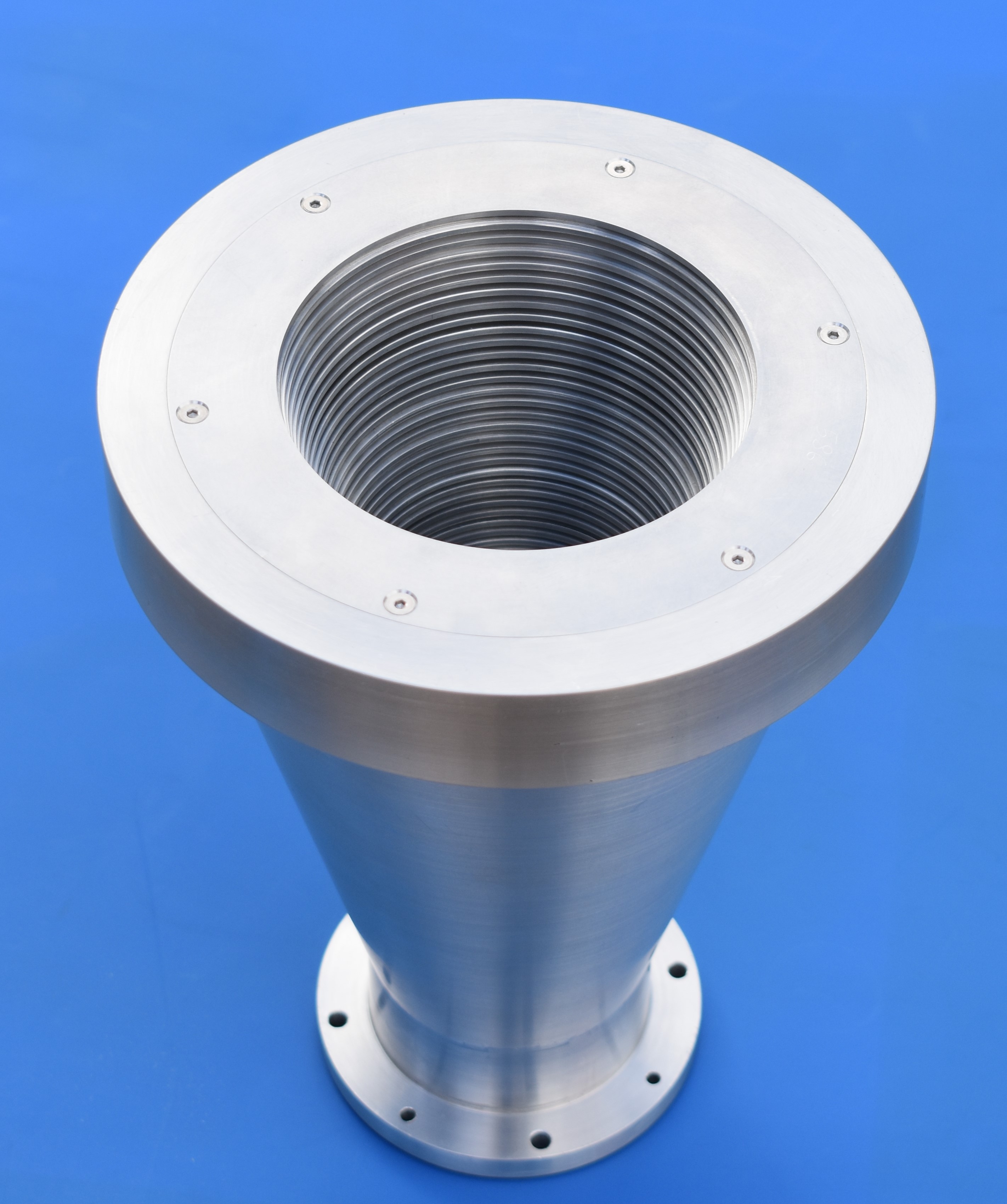
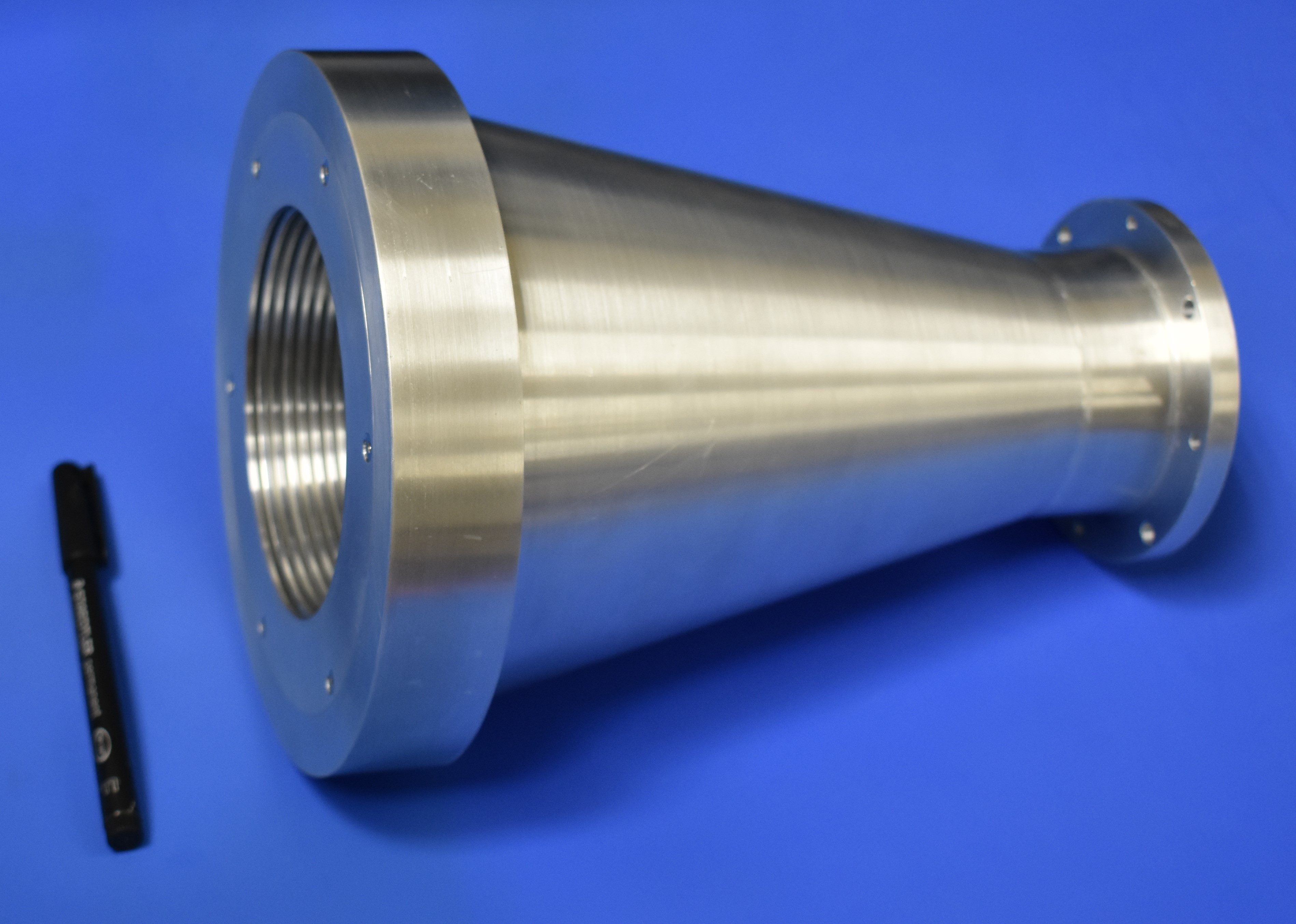
The 85 meta-rings of the horn were assembled into an Aluminum external shell, which provided stability to the structure. Manufacturing tolerance is satisfactory, with less than 30 m of deviation from the nominal value. The metrological analysis was carried out with a coordinate measuring machine following the same methodology described in [11], i.e. measuring diameter, roundness, thickness and parallelism. A thermally stabilized environment prevented possible deviations due to the expansion or contraction of the materials. By measuring coordinates of one or several points, the machine allowed both dimensional and geometric measurements. Each piece was fixed on the machine bench before making measurements. We had to establish one or more reference system for each piece depending on the dimensions to be verified. In addition, each measurement was processed by multi-point adjustment to average the error. The resolution of the machine is of the order of a few microns.
The electromagnetic measurements were made within an anechoic chamber. For this operation, the 10–20 GHz band was divided into sub-bands defined by the standard commercial bands for microwave components, so all the waveguides operate in a monomode regime. Thus, the experimental set-up includes WR-75 standard gain horns, WR75 FBP120 to SMA-F adapters, and a 20 mm diameter circular-to-rectangular waveguide transition covering the 10–15 GHz range; the 15–20 GHz sub-band is covered by WR-51 standard gain horns, WR51 FBP180 to SMA-F adapters and a 20 mm diameter circular-to-rectangular (FBP180 flange) waveguide transition. Both customized circular-to-rectangular transitions are used to connect the rectangular waveguides of the standard components to the meta-horn, which has a 20 mm diameter input.
Radiation patterns and gain are measured in the far field regime. In each sub-band, a standard pyramidal horn antenna acts as a transmitter (Tx) and it is placed about 3660 mm from the antenna under test. The meta-horn far field regime is 1415 mm at its highest frequency (20 GHz), so that the distance between the Tx antenna and the meta-horn during the measurements is at least 2.6 times the far-field distance. The alignment between the Tx antenna and the meta-horn when mounted on their mechanical support structures is performed with a laser and it is verified by means of preliminary radio frequency (RF) measurements. The polarization alignment is performed by minimizing the cross-polar signal when the two antennas are aligned along their boresight. No significant dynamic range limitations exist thanks to the use of a stable external source directly connected to the Tx antenna, thus preventing power losses through long cables to the Vector Network Analyzer (VNA). The receiver is based on a mixer-diplexer chain connected to the SMA adapter, easily accessible on the back side of the polarization rotary table.
The phase of the signal produced by the external generator is unknown to the VNA, so it is necessary to have a reference (fixed) antenna for phase measurement and power stability verification. This is the reason why this set-up requires two standard gain horns for each sub-band. This set-up guarantees optimal dynamics with respect to standard S21 measurements at the VNA ports. As a drawback, it prevents the usage of a real-time time-domain filtering; however, the anechoic environment guarantees negligible spurious reflections during the measurements.
The meta-horn gain is measured with a gain transfer technique, i.e. by replacing the antenna under test with a calibrated gain antenna and comparing their output. The effect of waveguide transitions and cable adapter is also de-embedded by measuring their frequency response with dedicated VNA measurements. This is repeated for both 10–15 and 15–20 GHz sub-ranges.
Finally, the return-loss is measured with the antenna mounted on its mechanical support structure while pointing towards the anechoic chamber walls to minimize any spurious contribution from the environment. A time-domain filtering is also applied to verify possible reflections due to the waveguide and cable adapters, as well as possible mechanical misalignments at the of the RF chain interfaces.
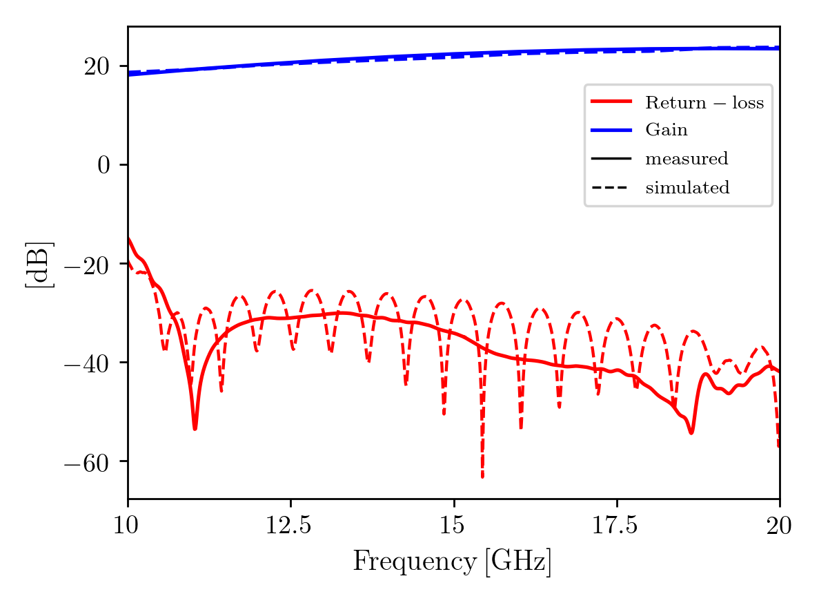
The simulated performance of the meta-horn show a return-loss better than dB, side-lobe level better than dB, cross-polarization level better than dB and a 20 dBi gain feature in the 10–20 GHz band, approximately. These performance have been verified in the bandwidth by measurements, as discussed here below.
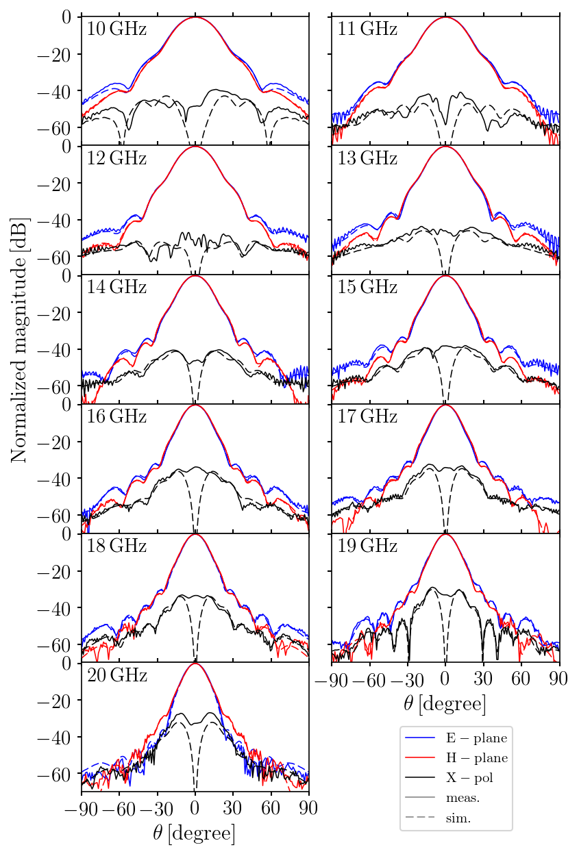
Figure 7 shows a comparison between measurements (solid line) and simulations (dashed line) for the meta-horn return-loss (red) and gain (blue), resulting in a excellent agreement and consistency over the 10–20 GHz frequency band. Fig. 8 reports the radiation patterns as measured between 10 and 20 GHz with 1 GHz step. Each plot includes the co-polar E- and H-planes and the cross-polar 45°-plane as compared to the relevant simulation. The agreement between measurements and simulation is at the level of fractions of a dB down to the first side-lobe at all frequencies. Moreover, the cross-polar level predicted by simulations is confirmed by meta-horn measurements. A few dB discrepancy is observed at 11 and 20 GHz,555We think that such a discrepancy has an instrumental-experimental origin. Although minor, this will be further investigated in the future. nevertheless guaranteeing a cross-polar maximum level below -40 and -35 dB, respectively.
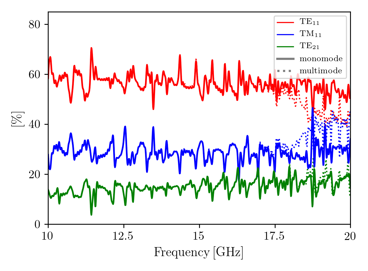
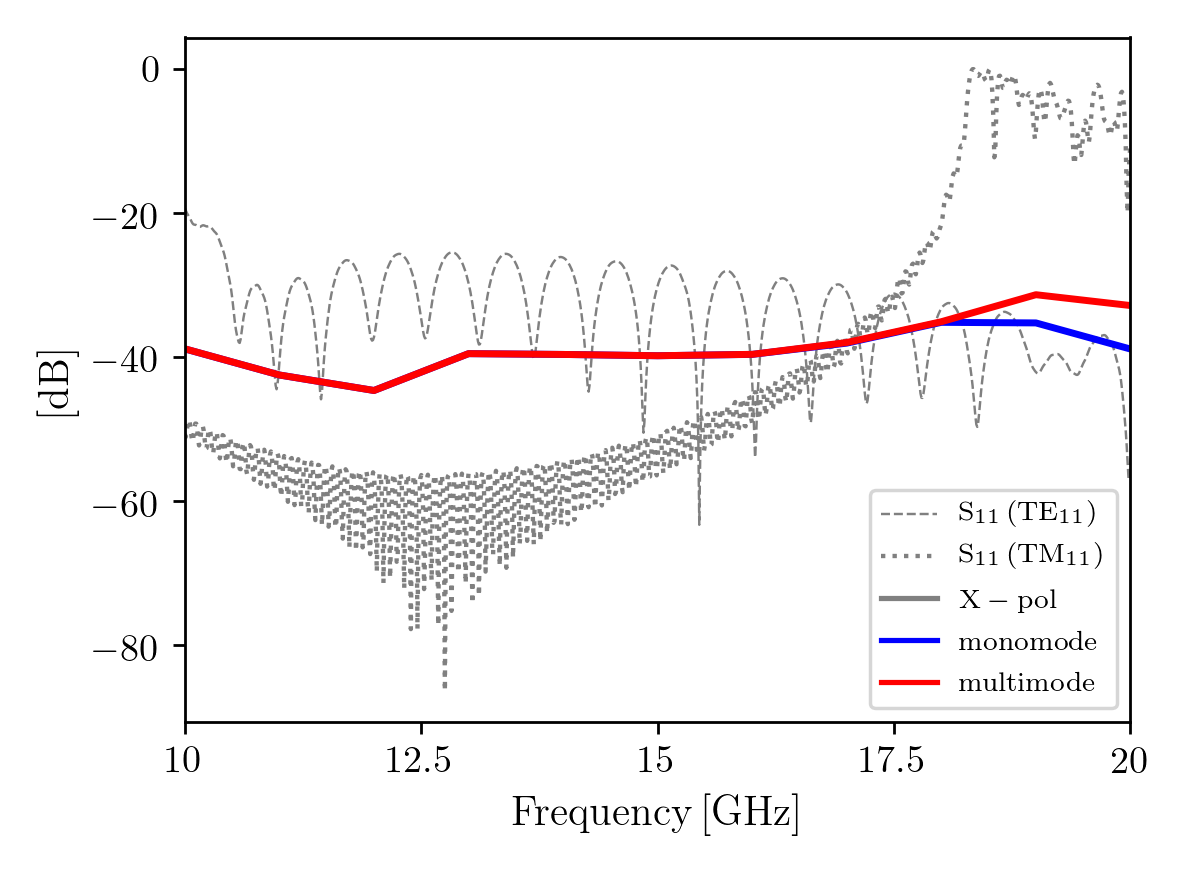
Theory can help interpret these results. At an early design stage we noticed that, because of the ultra-wide bandwidth of the meta-horn, it was not possible to maintain only the fundamental mode (TE11) at the feeding waveguide for a single-mode operation through the complete 2:1 factor band. Simulations results in Fig. 9 suggest that around 60% of the energy is transmitted in the fundamental mode at the output of the meta-horn in the monomodal feed-guide case, and that the remaining power is divided into higher-order modes (mainly TM11 and TE21), slightly differing from the HE11 hybrid mode decomposition [16] in power. One might think that reducing the radius of the feeding waveguide below a critical size666For this prototype, a feeding waveguide diameter less than about 9.3 mm raises the cut-off frequency of the mode TM11 above 20 GHz. could be enough for providing an optimal single-mode operation. Unfortunately, a significant feed-guide radius reduction has a negative effect on return-loss that cannot be easily surpassed. On the other hand, simulations with a toy model reveal that optimization with the goal of hybrid-mode condition fulfilment or with the goal of cross-polarization minimization tends to differ slightly, pointing to a higher complexity of the issue from the analytical point of view. This could be explained in the sense that, in a real horn, several factors influence antenna performance, such as the aperture, the length and the profile, as well as the surface impedance as treated throughout this project [7] [10]. Furthermore, the modal distribution typically varies through the length (and aperture) of a horn, so different planes (e.g., input and output) can have a different modal decomposition. Obviously, the presence of the TE21 mode displaces the presence of other modes with respect to the ideal HE11, in whose decomposition this mode is not present. The weight of higher-order modes is even more significant when a multimode feeding waveguide is considered. This is represented in Fig. 9 (dashed line), in comparison to the single-mode operation regime, represented by a solid line. The power modal decomposition seems to have an influence on cross-polarization, and a negligible influence on the other figures of merit of the meta-horn. The influence on cross-polarization is represented in Figure 10.
More conclusions and future lines are to be discussed in the following section.
4 Summary and conclusions
In this article we presented a proof-of-concept prototype of an innovative horn antenna based on a novel kind of meta-ring which gives the remarkable advantage of easy manufacture at a low cost. The meta-horn gives a good performance (return-loss better than dB, side-lobe level better than dB, cross-polarization level better than dB and gain around 20 dBi) over a broad band, with a 2:1 bandwidth factor (see Figs. 7 and 8).777Measured gain represented in Fig. 7 results from a second order polynomial curve fit of ten gain measurements between 10–20 GHz in 1 GHz steps. It is important to emphasize that the device is tunable in frequency by simply scaling its dimensions accordingly, with an upper limit established by the capacity of a workshop during the mechanization of the meta-rings. This would allow one to cover a significant part of the radio frequency spectrum from a few GHz up to hundreds.888Our simulations reveal that a regular workshop, like the one which manufactured the prototype presented here, is suitable for the production of a meta-horn at frequencies over 200 GHz and probably beyond.
Finally, the meta-horn presented in this work is the result of a design with reduced complexity. For example, it presents a conical profile and a limited number of meta-rings in order to simplify the fabrication process in a proof-of-principle prototype. Therefore, we believe that it has a significant potential for improvement and a large margin for a further research, incorporating also the know-how acquired during the fabrication and lab verification processes. We found also that the Method of Moments (MoM) is more reliable than FEM in the simulation of the antenna pattern, in contrast with our previous expectations.999With SRSR-D or Mician Wave Wizard compared to CST. This could help in a future (re-)design stage.
In addition, The meta-horn presented here was optimized for single-mode operation, since a monomode broad band feed-guide can be incorporated [17] [18]; however, the idea of living with higher order modes and shaping them according to specific purposes is also very attractive for future applications. Given this, a more control over the TM11 mode would give an improvement of the meta-horn cross-polarization up to levels under dB or less in the multimode regime through a 2:1 bandwidth factor, as shown in Figs. 9 and 10, while mitigating the side-lobes. We identified several areas to explore the full potential of the meta-horn, such as shaping the horn with a smart curve profile instead of a conical profile (e.g., Gaussian [15]) or adding length to the antenna (thus increasing the number of meta-rings) in combination with a further computer aided optimization. This would make it possible to simultaneously cover both the Ka and Ku bands with a single receiver for satellite communications, or to cover broader bands reducing the complexity and enhancing the sensitivity of telescopes for radio astronomy [19] [20].
Acknowledgements
The authors would like to thank R. Hoyland and M. Bersanelli their support making possible bringing the present work to fruition. Thanks C. del Río for comments.
JDM acknowledges financial support from the Spanish Ministry of Science and Innovation under the FEDER Agreement INSIDE-OOCC (ICTS-2019-03-IAC-12). Also the financial support from projects IACA15-BE-3707 and EQC2018-004918-P, and the Severo Ochoa Program SEV-2015-0548.
Data release
The data and a 3D model of the meta-horn are available for non-military use upon request. The antenna model is parametrized, allowing rapid prototyping in a different operating band.
References
- [1] D. Schurig, J. Mock, B. Justice, S. Cummer, J. Pendry, A. Starr et al., Metamaterial electromagnetic cloak at microwave frequencies, Science (New York, N.Y.) 314 (2006) 977.
- [2] D. Sievenpiper, High-impedance electromagnetic surfaces, Ph.D. thesis, University of California, Los Angeles, 1999.
- [3] D. Sievenpiper, L. Zhang, R. F. J. Broas, N. G. Alexopolous and E. Yablonovitch, High-impedance electromagnetic surfaces with a forbidden frequency band, IEEE Transactions on Microwave Theory and Techniques 47 (1999) 2059.
- [4] D. F. Sievenpiper, J. H. Schaffner, H. J. Song, R. Y. Loo and G. Tangonan, Two-dimensional beam steering using an electrically tunable impedance surface, IEEE Transactions on Antennas and Propagation 51 (2003) 2713.
- [5] E. Lier, D. H Werner, C. Scarborough, Q. Wu and J. A Bossard, An octave-bandwidth negligible-loss radiofrequency metamaterial, Nature Materials 10 (2011) 252.
- [6] C. Scarborough, Advanced Antennas Enabled By Electromagnetic Metamaterials, Ph.D. thesis, Penn State University, 2014.
- [7] J. De Miguel-Hernández and R. Hoyland, Fundamentals of horn antennas with low cross-polarization levels for radioastronomy and satellite communications, Journal of Instrumentation 14 (2019) R08001.
- [8] D. Ramaccia, F. Scattone, F. Bilotti and A. Toscano, Broadband compact horn antennas by using eps-enz metamaterial lens, IEEE Transactions on Antennas and Propagation 61 (2013) 2929.
- [9] E. Lier, D. H. Werner and T. S. Bird, The evolution from metal horns to metahorns: The development of em horns from their inception to the present day, IEEE Antennas and Propagation Magazine 61 (2019) 6.
- [10] P. Clarricoats and A. Olver, Corrugated horns for microwave antennas, vol. 18. IEE Electromagnetic Waves Series, 1984.
- [11] J. De Miguel, R. J. Hoyland, D. Sosa-Cabrera, S. Deviaene, P. A. Fuerte-Rodríguez, E. D. González-Carretero et al., Manufacturing of 3D-metallic electromagnetic metamaterials for feedhorns used in radioastronomy and satellite communications, Mechanics of Materials 139 (2019) 103195.
- [12] R. H. Dicke, The measurement of thermal radiation at microwave frequencies., The Review of scientific instruments 17 (1946) 268.
- [13] H. C. Minnett and B. MacA. Thomas, A method of synthesizing radiation patterns with axial symmetry, Antennas and Propagation, IEEE Transactions on AP-14 (1966) 654 .
- [14] A. Ludwig, The definition of cross polarization, IEEE Transactions on Antennas and Propagation 21 (1973) 116.
- [15] R. Gonzalo, J. Teniente and C. del Rio, Improved radiation pattern performance of gaussian profiled horn antennas, IEEE Transactions on Antennas and Propagation 50 (2002) 1505.
- [16] A. Boriskin and R. Sauleau, Aperture Antennas for Millimeter and Sub-Millimeter Wave Applications. Springer, 09, 2017, 10.1007/978-3-319-62773-1.
- [17] M. A. Morgan and T. A. Boyd, A 10–100-ghz double-ridged horn antenna and coax launcher, IEEE Transactions on Antennas and Propagation 63 (2015) 3417.
- [18] A. R. Mallahzadeh, A. A. Dastranj and S. Akhlaghi, Quad-ridged conical horn antenna for wideband applications, International Journal of RF and Microwave Computer-Aided Engineering 19 (2009) 519 [https://onlinelibrary.wiley.com/doi/pdf/10.1002/mmce.20374].
- [19] J. De Miguel-Hernández, R. J. Hoyland, M. F. Gómez Reñasco, J. A. Rubiño-Martín and T. A. Viera-Curbelo, A high-sensitivity fourier transform spectrometer for cosmic microwave background observations, IEEE Transactions on Instrumentation and Measurement 69 (2020) 4516.
- [20] J. De Miguel and R. J. Hoyland, Feasibility of cosmic microwave background observations using radiometers based on whispering gallery mode resonators, New Astronomy (2020) 101367.