Magnon transport in /Pt nanostructures with reduced effective magnetization
Abstract
For applications making use of magnonic spin currents damping effects, which decrease the spin conductivity, have to be minimized. We here investigate the magnon transport in an yttrium iron garnet thin film with strongly reduced effective magnetization. We show that in a three-terminal device the effective magnon conductivity can be increased by a factor of up to six by a current applied to a modulator electrode, which generates damping compensation above a threshold current. Moreover, we find a linear dependence of this threshold current on the applied magnetic field. We can explain this behavior by the reduced effective magnetization and the associated nearly circular magnetization precession.
Pure spin currents carried by magnons, the elementary excitations of the spin system in magnetically ordered insulators (MOIs), have drawn much attention due to their potential applications in information processing at a low dissipation level [1, 2, 3, 4]. The MOI yttrium iron garnet (, YIG) is a promising candidate for hosting efficient magnon based spin transport due to its low Gilbert damping parameter even in nanometer-thin films [5] and its correspondingly large magnon propagation length [6, 7, 8, 9]. Amongst the device concepts enabling logic operation with magnonic spin currents, transistor-inspired devices and even logic gates have been demonstrated [4, 10, 11, 12, 13]. Such transistor-like device concepts generally rely on spin-transfer torque for spin current generation. The latter can be realized in bilayers consisting of MOIs and heavy metals with strong spin-orbit coupling via the spin Hall effect (SHE) [14, 15, 7, 16, 17, 18, 19, 20, 21]. The magnon transport in the MOI can be controlled via an electrical charge current, and the resulting effect is typically represented by a change in the effective magnon conductivity [4, 10]. At a certain threshold current the injected magnons can even counteract the magnetization damping, which results in an abrupt increase of the effective magnon conductivity. The present understanding is that this threshold effect scales with the saturation magnetization and the magnetic anisotropy of the materials [22, 10]. This warrants to explore the impact of these parameters on controlling the magnon conductivity in MOIs, which has not been pursued so far to the best of our knowledge.
In this Letter, we investigate the diffusive magnon transport in MOIs with significant perpendicular magnetic anisotropy fields and reduced . To this end, we biaxially strain the YIG thin film hosting the magnons by growing YIG on yttrium scandium gallium garnet (, YSGG). Our films exhibit low Gilbert damping comparable to YIG thin films grown on lattice-matched substrates. By investigating the magnon transport in three-terminal devices, we find that the threshold current, which defines the onset of the regime with compensated damping, depends linearly on the applied magnetic field. Moreover, we can corroborate the expected scaling with the effective magnetization of the MOI.
Our experimental approach utilized to enhance the magnon-based spin conductivity is based on the minimization of the ellipticity of the magnetization precession. As sketched in Fig. 1(a), YIG thin films grown on the lattice-matched substrate gadolinium gallium garnet (, GGG) exhibit a finite in-plane effective magnetization , and thus an elliptical magnetization precession trajectory with the long axis aligned in the film plane, giving rise to nonlinear damping effects via parametric pumping of higher frequency magnon modes [23]. Recent experiments reported the minimization of the ellipticity of the magnetization precession (approaching ) and thereby achieved spin-orbit torque induced coherent magnetization auto-oscillations even in extended magnetic films [24, 25]. For our experiments, we also reduce the ellipticity of the magnetization precession by reducing the effective magnetization of YIG. Approaching , a circular magnetization precession is expected and, hence, nonlinear damping effects should be suppressed (cf. Fig. 1(b)).
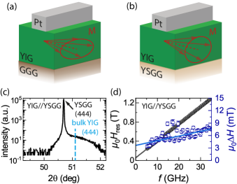
To be able to control , we biaxially strain the thick YIG film by growing it pseudomorphically onto an YSGG substrate by pulsed laser deposition (see the Supplemental Material (SM) 111 See Supplemental Material at [url], which contains information on the sample fabrication, measurement procedure and a derivation of the used fitting functions for the critical modulator current. It contains Ref. [37]. for growth details). The lattice mismatch of between YIG and YSGG induces a biaxial in-plane tensile strain in the YIG thin film. This strain can result in a strong [27], originating from the strain-induced magnetoelastic coupling [28]. Fig. 1(c) shows the x-ray diffraction scan of the thin film confirming the in-plane lattice strain. The substrate (444) diffraction peak is clearly visible at , while the corresponding broad film peak is shifted to larger values due to the tensile strain and appears as a shoulder in the diffration pattern. Note, that the large width and low intensity of the film peak is due to the small film thickness. We magnetically characterize the strained YIG film using broadband ferromagnetic resonance (FMR) as shown in Fig. 1(d). We determine the effective magnetization of the thin film by extracting the resonance field applied in the out-of-plane direction as a function of the stimulus frequency of the microwave radiation and linear fitting with the Kittel equation. This value is about three times smaller compared to unstrained YIG films of similar thickness [10]. Moreover, FMR enables us to determine the Gilbert damping parameter (see Fig. 1(d)) [29]. By fitting the FMR linewidth to (blue line) with the gyromagnetic ratio with the Landé factor and Bohr’s magneton , we obtain the inhomogenous FMR linewidth and . Similar values for were obtained for an epitaxial high-quality YIG film grown on lattice-matched GGG under the same conditions [10].
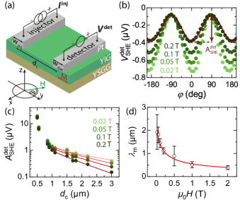
As a next step, we deposit ex-situ thick Pt strips on top of the strained YIG film using electron beam lithography and magnetron sputtering, allowing for an all-electrical generation and detection of pure spin currents [4]. With this sample, we investigate diffusive magnon transport using twin-strip structures as depicted in Fig. 2(a). In our experiments a DC charge current is fed through one Pt strip (injector) to inject magnons into the YIG via the SHE. The magnons diffuse away from the injector and can then be electrically detected via the inverse SHE at the second Pt strip (detector) as a voltage signal . In our sample a constant injector width of is used, while the detector width and the center-to-center distance between injector and detector is varied. Using a current reversal technique we unambiguously can assign the measured detector voltage to the magnons generated at the injector via the SHE [16, 13]. To characterize the magnon transport, we measure the voltage signal as a function of the magnetic field orientation (cf. Fig. 2(a)) with fixed magnitude at a temperature of . The data is shown in Fig. 2(b) for and . The results show the distinctive angular variation expected for diffusive transport of SHE-generated magnons from injector to detector [4, 16]. The angle dependence can be fitted with a simple function, as exemplary shown for , where corresponds to the amplitude of the SHE-induced magnon transport signal. The quantity is plotted in Fig. 2(c) as a function of for different . We observe a decrease of with increasing as expected for diffusive magnon transport: at distances shorter than the magnon diffusion length , follows a dependence, while for larger distances the magnon relaxation dominates and an exponential decay is observed [7, 19]. An exponential fit to the data measured for (red lines), allows us to extract . The extracted values are shown in Fig. 2(d) as a function of the magnetic field magnitude . The values are of the order of and thus in good agreement with the values found for YIG films grown on lattice-matched GGG [10]. To discuss the physics leading to the magnetic field dependence of in more detail, we consider the magnon relaxation rate , which is given by
| (1) |
for an in-plane magnetized film [30]. Taking damping contributions from inhomogenous broadening into account [31], the damping rate diverges for a finite positive at . However, in the limit of , the relaxation rate is constant for and we expect a strictly linear dependence on the magnetic field. Together with and with the magnon diffusion constant and the magnon lifetime, we can describe the magnetic field dependence of determined from the twin-strip transport measurements as
| (2) |
As shown in Fig. 2(d), the experimental data can be well fitted by Eq. (2). Utilizing the values obtained from the FMR measurements and neglecting the field dependence of , we obtain a magnon diffusion constant of . Similar values were obtained for YIG films on GGG, supporting the quantitative understanding of the phenomenon [32].
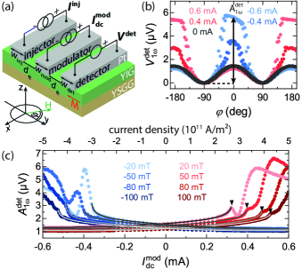
Next, we turn to three-terminal devices, which allow us to manipulate the magnon transport between injector and detector via the center Pt strip acting as modulator (see Fig. 3(a)). In this configuration, we apply a low-frequency () charge current to the injector strip, while a constant DC charge current is applied to the modulator strip. The detector voltage is recorded via lock-in detection, where the first harmonic voltage signal can be assigned to the transport of magnons generated via the SHE at the injector. We measure as a function of the magnetic field orientation for different external magnetic field magnitudes and different modulator currents . Exemplary results for a structure with an edge-to-edge distance and a modulator width , while and , are plotted in Fig. 3(b). For (black data points), exhibits the same variation as in our twin-strip structures [4, 16]. As reported previously [10, 11], we observe a significant enhancement of at for . This observation can be attributed to a magnon accumulation underneath the modulator caused by the SHE-induced magnon chemical potential and thermally generated magnons due to Joule heating. This accumulation increases the magnon conductivity, resulting in a larger voltage signal . At , the magnon transport signal is slightly suppressed, originating from the nearly compensation of the magnon depletion caused by the SHE by thermally generated magnons. For , we observe a shifted angle dependence of the detector voltage signal, i.e. an increase at and a reduction at . This behavior is fully consistent with the assumption that there are both SHE and Joule heating contributions [4, 10, 11]. For a more quantitative analysis, we extract the signal amplitudes at and at and plot them as a function of the modulator current for different in Fig. 3(c). For , we observe the expected superposition of a linear and quadratic dependence corresponding to SHE induced magnons and thermally generated magnons due to Joule heating, respectively [4, 10, 11]. However, for larger a clear deviation from this behavior is observed. In particular, we observe a strongly increased signal amplitude . This observation can be attributed to an enhanced effective magnon conductivity underneath the modulator, which causes a strong increase of the detector signal at the same magnon injection rate at the injector. As reported previously [10], this enhanced magnon conductivity can be explained by the presence of a zero effective damping state generated below the modulator electrode via the SHE-mediated spin-orbit torque. We here observe a maximum enhancement of by a factor of 6, a twofold increase as compared to our previous experiments. This strong enhancement can be attributed to the reduction in and the associated circular magnetization precession. For the two magnetic field polarities, we observe an asymmetry for in the amplitude signal . This is in stark contrast to the results obtained for YIG films on lattice-matched GGG [10, 11]. At present, we can only speculate about the detailed origin of this asymmetry. It may be related to a combination of the following aspects: (i) a misalignement of the magnetic field due to trapped flux from our 3D-vector magnet, (ii) a Joule heating induced modification of the device properties, or (iii) effects related to the crystalline-orientation of YIG. The previously investigated YIG films were (001)-oriented [10], while here we use a (111)-orientation allowing us to make use of the crystalline magnetic anisotropy.
The zero effective damping state and the corresponding peak-like structure in the magnon conductivity at the threshold value was recently discussed by S. Takei [33]. According to this model considerations, one can express the expected dependence of originating from the thermal and SHE injection of magnons by
| (3) |
where the proportionality factors account for the induced magnon conductivity and , , and are used as fit parameters. Note that the model is only valid up to and we thus restrict the fit with Eq. (3) to this region. The fit, indicated by gray lines in Fig. 3(c), reproduces well the measured data points. Although this model does not account for the amplitude asymmetry, it is well suited to extract the threshold current .
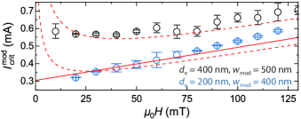
For a quantitative comparison of the strained YIG films with reduced and conventional YIG thin films on GGG, we rely on the dependence of with in Fig. 4. For the discussed structure (blue circles), we observe a linear increase of the critical current with applied magnetic field for . This is in contrast to the observations in Ref. [10] (black circles), where an increase in with is only observed for , while for remains constant. We note that vs was associated with damping compensation [10]. Here, the spin injection rate due to SHE results in an interfacial spin transfer torque , which balances the intrinsic damping of the material. Hence, zero effective damping is achieved, when the condition is satisfied [30]. In this regime, we can define the critical modulator current as [10]
| (4) |
where is the elementary charge, the spin Hall angle of Pt, the field dependent damping rate 222 taking into account inhomogenous broadening. Furthermore, denotes the effective spin mixing conductance 333 and , which depends on the interface spin mixing conductance , the spin diffusion length , thickness , and electrical conductivity of Pt (see SM References11footnotemark: 1). The variation of with the applied magnetic field taken from Ref. [10] is quantitatively well described by the theoretical model (dashed line). Fitting our data with Eq. (4), we use , (from SQUID magnetometry measurements see SM References11footnotemark: 1), , [36] and . Furthermore, we use the values of and extracted from the FMR measurements, while is the only free fit parameter. We observe good quantitative agreement for large magnetic field magnitudes, but find a clear deviation for . However, if we assume , the fit (solid line) corroborates our observed linear magnetic field dependence of in Fig. 4. Moreover, the linear dependence on is in accordance with the results by Evelt et al., who studied Bi:YIG thin films with PMA and nearly vanishing [24]. Fitting the data, we obtain and in the limit of , comparable to YIG/Pt structures on GGG [10]. Deviations between fit and data are potentially caused by uncertainties in the fixed parameters, as for example and are determined from out-of-plane FMR.
In summary, we investigate magnon transport in YIG with strongly reduced induced via biaxial strain from growth on YSGG substrates [27]. Performing angle-dependent measurements in twin- and three-terminal devices, we find a quantitatively similar behavior as observed for YIG films on GGG for small modulator currents , while differences occur above the threshold value when damping compensation is reached. Most importantly, we observe an increase of the magnon induced detector signal by a factor of about 6, which is much larger than reported previously [10]. Another important difference is the strictly linear field dependence of . This interesting observation can be attributed to the nearly vanishing in our film confirming the expected scaling of the threshold behavior with and . Our work provides an important step towards the detailed understanding of magnon transport in systems far from equilibrium and the basis for applications based on pure spin currents.
Acknowledgements.
We gratefully acknowledge financial support from the Deutsche Forschungsgemeinschaft (DFG, German Research Foundation) under Germany’s Excellence Strategy – EXC-2111 – 390814868 and project AL2110/2-1.References
- Chumak et al. [2015] A. V. Chumak, V. I. Vasyuchka, A. A. Serga, and B. Hillebrands, Magnon spintronics, Nature Physics 11, 453 (2015).
- Chumak et al. [2017] A. V. Chumak, A. A. Serga, and B. Hillebrands, Magnonic crystals for data processing, Journal of Physics D: Applied Physics 50, 244001 (2017).
- Nakata et al. [2017] K. Nakata, P. Simon, and D. Loss, Spin currents and magnon dynamics in insulating magnets, Journal of Physics D: Applied Physics 50, 114004 (2017).
- Cornelissen et al. [2018] L. J. Cornelissen, J. Liu, B. J. van Wees, and R. A. Duine, Spin-current-controlled modulation of the magnon spin conductance in a three-terminal magnon transistor, Physical Review Letters 120, 097702 (2018).
- Cherepanov et al. [1993] V. Cherepanov, I. Kolokolov, and V. L’vov, The saga of YIG: Spectra, thermodynamics, interaction and relaxation of magnons in a complex magnet, Physics Reports 229, 81 (1993).
- Kajiwara et al. [2010] Y. Kajiwara, K. Harii, S. Takahashi, J. Ohe, K. Uchida, M. Mizuguchi, H. Umezawa, H. Kawai, K. Ando, K. Takanashi, S. Maekawa, and E. Saitoh, Transmission of electrical signals by spin-wave interconversion in a magnetic insulator, Nature 464, 262 (2010).
- Cornelissen et al. [2015] L. J. Cornelissen, J. Liu, R. A. Duine, J. B. Youssef, and B. J. van Wees, Long-distance transport of magnon spin information in a magnetic insulator at room temperature, Nature Physics 11, 1022 (2015).
- Yu et al. [2016] H. Yu, O. d’Allivy Kelly, V. Cros, R. Bernard, P. Bortolotti, A. Anane, F. Brandl, F. Heimbach, and D. Grundler, Approaching soft x-ray wavelengths in nanomagnet-based microwave technology, Nature Communications 7, 11255 (2016).
- Liu et al. [2018] C. Liu, J. Chen, T. Liu, F. Heimbach, H. Yu, Y. Xiao, J. Hu, M. Liu, H. Chang, T. Stueckler, S. Tu, Y. Zhang, Y. Zhang, P. Gao, Z. Liao, D. Yu, K. Xia, n. Lei, W. ZHAO, and M. Wu, Long-distance propagation of short-wavelength spin waves, Nature Communications 9, 738 (2018).
- Wimmer et al. [2019] T. Wimmer, M. Althammer, L. Liensberger, N. Vlietstra, S. Geprägs, M. Weiler, R. Gross, and H. Huebl, Spin transport in a magnetic insulator with zero effective damping, Physical Review Letters 123, 257201 (2019).
- Gückelhorn et al. [2020] J. Gückelhorn, T. Wimmer, S. Geprägs, H. Huebl, R. Gross, and M. Althammer, Quantitative comparison of magnon transport experiments in three-terminal YIG/Pt nanostructures acquired via dc and ac detection techniques, Applied Physics Letters 117, 182401 (2020).
- Santos et al. [2021] O. A. Santos, F. Feringa, K. S. Das, J. B. Youssef, and B. J. van Wees, Efficient modulation of magnon conductivity in using anomalous spin hall effect of a permalloy gate electrode, Physical Review Applied 15, 014038 (2021).
- Ganzhorn et al. [2016] K. Ganzhorn, S. Klingler, T. Wimmer, S. Geprägs, R. Gross, H. Huebl, and S. T. B. Goennenwein, Magnon-based logic in a multi-terminal YIG/Pt nanostructure, Applied Physics Letters 109, 022405 (2016).
- Hirsch [1999] J. E. Hirsch, Spin hall effect, Physical Review Letters 83, 1834 (1999).
- Dyakonov and Perel [1971] M. I. Dyakonov and V. I. Perel, Possibility of orienting electron spins with current, Journal of Experimental and Theoretical Physics Letters 13, 467 (1971).
- Goennenwein et al. [2015] S. T. B. Goennenwein, R. Schlitz, M. Pernpeintner, K. Ganzhorn, M. Althammer, R. Gross, and H. Huebl, Non-local magnetoresistance in YIG/Pt nanostructures, Applied Physics Letters 107, 172405 (2015).
- Vélez et al. [2016] S. Vélez, A. Bedoya-Pinto, W. Yan, L. E. Hueso, and F. Casanova, Competing effects at Pt/YIG interfaces: Spin hall magnetoresistance, magnon excitations, and magnetic frustration, Physical Review B 94, 174405 (2016).
- Giles et al. [2015] B. L. Giles, Z. Yang, J. S. Jamison, and R. C. Myers, Long-range pure magnon spin diffusion observed in a nonlocal spin-seebeck geometry, Physical Review B 92, 224415 (2015).
- Shan et al. [2016] J. Shan, L. J. Cornelissen, N. Vlietstra, J. Ben Youssef, T. Kuschel, R. A. Duine, and B. J. van Wees, Influence of yttrium iron garnet thickness and heater opacity on the nonlocal transport of electrically and thermally excited magnons, Physical Review B 94, 174437 (2016).
- Althammer [2018] M. Althammer, Pure spin currents in magnetically ordered insulator/normal metal heterostructures, Journal of Physics D: Applied Physics 51, 313001 (2018).
- Althammer [2021] M. Althammer, All-electrical magnon transport experiments in magnetically ordered insulators (2021), arXiv:2103.08996 .
- Bender et al. [2014] S. A. Bender, R. A. Duine, A. Brataas, and Y. Tserkovnyak, Dynamic phase diagram of dc-pumped magnon condensates, Physical Review B 90, 094409 (2014).
- Suhl [1957] H. Suhl, The theory of ferromagnetic resonance at high signal powers, Journal of Physics and Chemistry of Solids 1, 209 (1957).
- Evelt et al. [2018] M. Evelt, L. Soumah, A. B. Rinkevich, S. O. Demokritov, A. Anane, V. Cros, J. Ben Youssef, G. de Loubens, O. Klein, P. Bortolotti, and V. E. Demidov, Emission of coherent propagating magnons by insulator-based spin-orbit-torque oscillators, Physical Review Applied 10, 041002(R) (2018).
- Divinskiy et al. [2019] B. Divinskiy, S. Urazhdin, S. Demokritov, and V. Demidov, Controlled nonlinear magnetic damping in spin-hall nano-devices, Nature Communications 10, 5211 (2019).
- Note [1] See Supplemental Material at [url], which contains information on the sample fabrication, measurement procedure and a derivation of the used fitting functions for the critical modulator current. It contains Ref. [37].
- Guo et al. [2019] C. Y. Guo, C. H. Wan, M. K. Zhao, H. Wu, C. Fang, Z. R. Yan, J. F. Feng, H. F. Liu, and X. F. Han, Spin-orbit torque switching in perpendicular /Pt bilayer, Applied Physics Letters 114, 192409 (2019).
- Popova et al. [2001] E. Popova, N. Keller, F. Gendron, L. Thomas, M.-C. Brianso, M. Guyot, M. Tessier, and S. S. P. Parkin, Perpendicular magnetic anisotropy in ultrathin yttrium iron garnet films prepared by pulsed laser deposition technique, Journal of Vacuum Science & Technology A 19, 2567 (2001).
- Maier-Flaig et al. [2018] H. Maier-Flaig, S. T. B. Goennenwein, R. Ohshima, M. Shiraishi, R. Gross, H. Huebl, and M. Weiler, Note: Derivative divide, a method for the analysis of broadband ferromagnetic resonance in the frequency domain, Review of Scientific Instruments 89, 076101 (2018).
- Hillebrands and Thiaville [2006] B. Hillebrands and A. Thiaville, Spin Dynamics in Confined Magnetic Structures III (Springer, Berlin, Heidelberg, 2006).
- Collet et al. [2016] M. Collet, X. De Milly, O. d. Kelly, V. V. Naletov, R. Bernard, P. Bortolotti, J. B. Youssef, V. Demidov, S. Demokritov, J. L. Prieto, M. Muoz, V. Cros, A. Anane, G. de Loubens, and O. Klein, Generation of coherent spin-wave modes in yttrium iron garnet microdiscs by spin–orbit torque, Nature communications 7, 10377 (2016).
- Cornelissen et al. [2016] L. J. Cornelissen, K. J. H. Peters, G. E. W. Bauer, R. A. Duine, and B. J. van Wees, Magnon spin transport driven by the magnon chemical potential in a magnetic insulator, Physical Review B 94, 014412 (2016).
- Takei [2019] S. Takei, Spin transport in an electrically driven magnon gas near bose-einstein condensation: Hartree-fock-keldysh theory, Physical Review B 100, 134440 (2019).
- Note [2] .
- Note [3] and .
- Althammer et al. [2013] M. Althammer, S. Meyer, H. Nakayama, M. Schreier, S. Altmannshofer, M. Weiler, H. Huebl, S. Geprägs, M. Opel, R. Gross, D. Meier, C. Klewe, T. Kuschel, J.-M. Schmalhorst, G. Reiss, L. Shen, A. Gupta, Y.-T. Chen, G. E. W. Bauer, E. Saitoh, and S. T. B. Goennenwein, Quantitative study of the spin Hall magnetoresistance in ferromagnetic insulator/normal metal hybrids, Physical Review B 87, 224401 (2013).
- Zhang et al. [2015] W. Zhang, W. Han, X. Jiang, S.-H. Yang, and S. Parkin, Role of transparency of platinum-ferromagnet interface in determining intrinsic magnitude of spin hall effect, Nature Physics 11, 496 (2015).