Air leakage in seals with application to syringes
Abstract
We study the leakage of air in syringes with Teflon coated rubber stopper and glass barrel. The leakrate depends on the interfacial surface roughness, the viscoelastic properties of the rubber and on the elastoplastic properties of the Teflon coating. The measured leakage rates are compared to the predictions of a simple theory for gas flow, which takes into account both the diffusive and ballistic air flow, and the elastoplastic multiscale contact mechanics which determines the probability distribution of interfacial separations. The theory shows that the interfacial air flow (leakage) channels are so narrow that the gas flow is mainly ballistic (the so called Knudsen limit). The implications for container closure integrity is discussed.
1 Introduction
All solids have surface roughness, which has a huge influence on a large number of physical phenomena such as adhesion, friction, contact mechanics and the leakage of seals[1, 2, 3, 4, 5, 6, 7, 8]. Thus when two solids with nominally flat surfaces are squeezed into contact, unless the applied squeezing pressure is high enough, or the elastic modulus of at least one of the solids low enough, a non-contact region will occur at the interface. If the non-contact region percolate, open flow channels exist, extending from one side of the nominal contact region to the other side. This will allow fluid to flow at the interface from a high fluid pressure region to a low pressure region.
We consider the leakage of air at the interface between a Teflon coated rubber stopper and a glass barrel. We have studied this problem in Ref. [9] but here we extend that study by using a new design of the stopper involving much higher contact pressures, where the contact is close to the percolation threshold.
Teflon (polytetrafluorethylen) and other films (e.g., ultra-high-molecular-weight polyethylene or ethylene-tetrafluorethylene-copolymer) are used in laminating rubber stoppers and have elastic modulus times higher than the typical rubbers stoppers (). Thus, the average interfacial separation, resulting from the surface roughness, is much larger than for the uncoated rubber stopper, and the contact area percolation threshold may not be achieved. Therefore, in any laminated rubber stoppers an accurate calculation of the interfacial separations as well as design parameters (contact pressure, geometry, etc…) is particularly important to assure container closure integrity, low weight losses, functional performance, and no microbial ingress during the shelf life and use of the product. One way to study the size of the most narrow constrictions in the open (percolating) channels at the stopper-barrel interface is by measuring the air leakage rate in syringes (with closed needle).
2 Experimental results
The Teflon laminated rubber stopper used in this study has three ribs 1-3 which contact the glass barrel. The ribs have (half) circular cross-section with the front and middle ribs with the diameter , and back rib 3 with the diameter . We first determine the width and the average contact pressure acting in the contact region. We also study the surface topography of the Teflon surface on the ribs. Finally we present the results of the air leakage experiments.
Nominal contact width
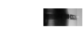
Using an optical microscope we have measured the width in the axial direction of the contact regions between the Teflon laminated rubber stopper and the glass barrel (see Fig. 1). The two inner ribs, 1 and 2, are nominally identical and with the contact width . The third (outer) rib 3 is wider but the contact pressure is much lower, and this rib has only a small influence on the air leakage rate. Note that the pressure is so high as to fully flatten the rib 1 and 2. We will assume below that the contact pressure is Hertzian-like but this is only a rough estimation because of the large deformations involved.
The old design of the stopper studied in Ref. [9] had two ribs, the inner rib with rectangular cross section with the contact width and back rib circular with the diameter . In this case the average contact pressure () is much lower than for the new design.
Average contact pressure
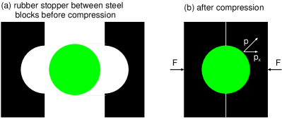
We have measured the average contact pressure between the stopper and the barrel using the set-up shown in Fig. 2. Two steel blocks with a cylinder cavity with the same radius as the inner radius of the barrel is squeezed together with the stopper inbetween, with such a force that the gap just closes without any repulsive force at the steel-steel contact. The steel surfaces are lubricated so negligible shear stress occurs in the contact between the stopper and the steel surface. If is the width in the axial direction of the contact region and if denotes the average pressure acting in the contact region between the stopper and the steel surface then
Thus where is the inner diameter of the barrel. Using this equation we can determine the average pressure acting on each rib by removing the other ribs. In the present case this shows that for the inner two ribs 1 and 2 (which are nominal identical with contact width ), the (average) contact pressure , and the maximal (Hertz) contact pressure , where we have used . The third (outermost) rib 3 is wider but the contact pressure much smaller, so this rib does not affect the air leakage rate.
Surface roughness power spectrum
The most important information about the surface topography of a rough surface is the surface roughness power spectrum. For a one-dimensional (1D) line scan the power spectrum is given by
where stands for ensemble averaging. For surfaces with isotropic roughness the 2D power spectrum can be obtained directly from as described elsewhere [10, 11]. For randomly rough surfaces, all the (ensemble averaged) information about the surface is contained in the power spectrum (see Ref. [5, 6]). For this reason the only information about the surface roughness which enter in contact mechanics theories (with or without adhesion) is the function . Thus, the (ensemble averaged) area of real contact, the interfacial stress distribution, and the distribution of interfacial separations, are all determined by .
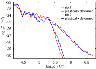
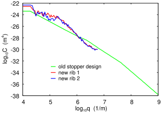
We have measured the surface roughness profile using a stylus instrument [Mitutoyo Portable Surface Roughness Measurement Surftest SJ-410 with a diamond tip with the radius of curvature , and with the tip-substrate repulsive force and the tip speed ], and calculated the surface roughness power spectrum as described in detail elsewhere[6]. The dashed lines in Fig. 3 shows the surface roughness power spectra obtained from stylus topography measurements on the rib 1 (red) and rib 2 (blue). The solid lines are the effective power spectra of the plastically deformed Teflon surfaces obtained as described in Ref. [12] and summarized below. In the calculation we have used the rubber modulus and Poisson ratio , the Teflon film thickness , the Teflon modulus and Poisson ratio , and the Teflon penetration hardness . The penetration hardness of Teflon (without filler) is typically in the range , but we interpret the lower penetration hardness we use as an effective hardness as the Teflon surface is exposed also to shear stresses and wear processes as it moves in the glass barrel, which smooth the surface. In addition, some plastic flow occur already when the contact pressure is well below the penetration hardness[13]. In fact, it has been observed that Teflon start to flow plastically around in wear experiments[14].
Here we note that the Persson contact mechanics theory assumes randomly rough surface roughness. However, plastic deformation in general result in non-random roughness. The procedure we use to obtain the power spectrum for plastically deformed surfaces has been described in detail elsewhere[12] but is briefly summarized here.
In elastic contact mechanics the contact area decreases continuously as we increase the magnification and observe shorter wavelength roughness. Hence, when a solid with surface roughness is squeezed against a flat rigid surface with the force the solid may deform elastically in the contact regions observed at low magnification, where the contact area is large and the contact stress low, but plastically above some critical magnification which depends on the penetration hardness. We take this plastic deformation into account by smoothing (or removing) the short wavelength roughness. We do this in such a way that the elastic contact area of the plastically deformed surface will be the same (as a function of magnification) as that obtained using the Persson elastoplastic contact mechanics theory[15, 16]. But in order for the surface to be randomly rough one must smooth the surface everywhere, i.e., also in the non-contact area. We have argued before[5, 17] that this has only a small influence of the interfacial separation in the open flow channels relevant for the fluid leakage problem. Nevertheless, the power spectrum obtained this way is an effective power spectrum designed for special purpose, and it cannot be compared to the real power spectrum obtained from the surface topography of the plastically deformed surface, as discussed in our earlier studies[18].
Leakage rate
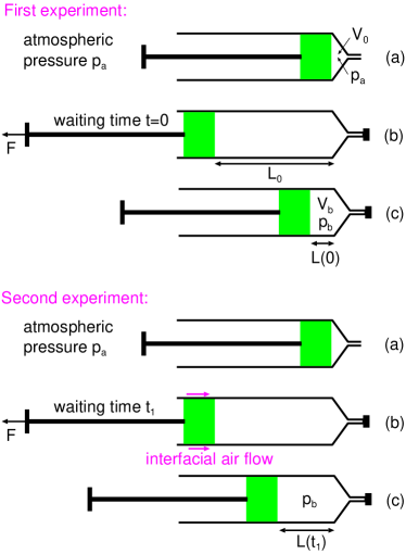
We have measured the air leakage in 15 syringes using the same procedure as in Ref. [9] and summarized in Fig. 4. We first assemble the barrel-stopper in empty configuration with the stopper pushed to the end of the barrel, resulting in a small volume of gas in the syringe at atmospheric pressure. Next the needle is closed so no air can penetrate into the syringe from the needle side, and the stopper is pulled back (retracted) to full fill position resulting in a volume of gas at low pressure. In the first experiment the pull-force is immediately removed, which results in the stopper moving to a new position where the gas pressure is such that the pressure force (due to the difference in the gas pressure outside and inside the barrel) is equal to the stopper-barrel friction force. Next we repeat the experiment except now the stopper is kept in the pulled back (retracted) position for some time . This results (due to air leakage at the barrel-stopper interface) in an increase in the air pressure, and when the pull force is removed after some time the stopper will move to a new position with . The volume increase is due to the air leakage into the syringe. However, the air pressure in the volume is not the atmospheric air pressure but is equal to . Thus, the correspond to a volume of air of atmospheric pressure. Since no leakage is assumed to occur during the first experiment we have so that . Hence the volume of air of atmospheric pressure leaking into the syringe per unit time equal
It is easy to study the leakage for each rib separately by introducing a thin cut in the other ribs through which the air (or fluid) can move with negligible resistance.
In our experiments, the pressure difference between inside and outside the syringe is about , and the average air leakage rate about . We repeated the test in five of the fifteen syringes obtaining very similar leakage result as in the initial measurements. In an earlier study (see Ref. [9]) with a different design of the Teflon coated rubber stopper, where the average contact pressure was much smaller, we observed larger air leakage rates, of order , i.e. about a factor of 20 higher than for the new design.
3 Analysis of experiments
The leakrate of fluids at interfaces between solids with random roughness can be calculated using the critical junction theory or the Bruggeman effective medium theory as described in detail elsewhere[21, 22, 23, 24, 25, 26, 27, 28, 29]. In the critical junction theory it is assumed that all the pressure drop in the fluid occurs at the most narrow constrictions along the biggest open (percolating) flow channels. The more accurate effective medium theory includes all flow channels in an approximate way but both theories gives usually very similar results. The probability distribution of interfacial separations, which enter in the theory for the leakage rate, is determined using the Persson contact mechanics theory[15, 30, 31, 22, 32]. In the present case, with the rubber stopper covered by a thin Teflon film, one must include the plastic deformations of the Teflon surface roughness profile, see Sec. 2 and Ref. [12].
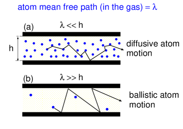
For the leakage of fluids one can usually assume laminar flow of Newtonian fluid characterized by a viscosity . This description is also valid for gases if the surface separation at the critical constriction is much larger than the gas molecule mean free path . However, this is not the case in the present application where the flow through the critical constriction is ballistic rather than diffusive, see Fig. 5. In Ref. [33, 34] we have presented an interpolation formula for gas flow through a narrow pore which correctly describes both the diffusive (large pore diameter) and ballistic (narrow pore diameter) limits. In the equation enters the viscosity , the mean free path and the average velocity of a gas molecules. We have used , and .
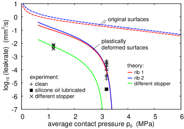
The solid and dashed lines in Fig. 6 shows the calculated leakage rate as a function of the average contact pressure using the plastically deformed surface (solid lines) and the original surface (dashed lines). The + symbols are the measured leakage rates using different (but nominally identical) clean syringes. The square symbol is for the same type of syringe, but with the glass barrel lubricated by silicone oil. The silicone oil block air flow channels and reduces the air leakage rate, and one may have expected an even larger reduction than observed. Note the crucial influence of the plastic deformation which for the relevant average contact pressure reduces the leakage rate by a factor of .
The maximum contact pressure for the rib contacts 1 and 2 is very close to the pressure where the contact area percolate. This result in the large fluctuations (by a factor of nearly 100) in the measured leakage rate between nominally identical syringes, and also in a large sensitivity in the calculated leakage rate to small variations in the system parameters, e.g., the penetration hardness.
The symbols in Fig. 6 are for a different Teflon coated rubber stopper studied in Ref. [9], where the rib contact regions are much wider and the contact pressure much smaller. For this stopper the Teflon coating was slightly smoother (see Fig. 7) than in this study, and when this is taken into account the theory prediction agrees very well with the measured data. This is shown by the green line in Fig. 6, which was calculated using the power spectrum of the plastically deformed surface obtained in the same way as for the rib 1 and 2. Note that the fluctuations in the measured data is much smaller than for the new stopper design, which is consistent with the fact that the contact pressure is well below the pressure where the contact area percolate.
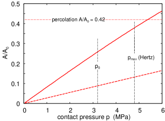
For a randomly rough surface the contact area percolate when (see Ref. [23]). When the contact area percolate no open flow channel occurs at the interface and the leakage rate vanish. Fig. 8 shows the contact area as a function of the contact pressure for rib 1. The solid line is for the plastically deformed surface and the dashed line for the originally (not deformed) Teflon surface. The dashed lines indicate the average and the maximum contact pressure assuming Hertz-like pressure distribution. Note that for the maximum contact pressure the contact area nearly percolate.
Container closure integrity is very important for syringes, so that no microorganism (bacteria and viruses) can penetrate from the outside to inside the syringe. The diameter of virus is in the range and it is clear that complete container closure integrity would imply that the most narrow junction (denoted critical junction) in the largest open (non-contact) interfacial channel should be at most . When this condition is satisfied, the fluid leakage is also negligible.
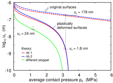
Fig. 9 shows the calculated surface separation at the critical constriction as a function of the average contact pressure using the plastically deformed surface (solid lines) and the original surface (dashed lines). The critical constriction is the most narrow constriction along the biggest open flow channels at the Teflon-glass interface. The separation of the surfaces at the critical constriction is , which implies container closure integrity.
The theory predict that the separation between the surfaces at the most narrow constrictions along the biggest fluid flow channels is so small () that also for the old design no bacterial ingress is possible, which has been confirmed experimentally.
4 Discussion
The study presented in this paper and in Ref. [9, 35] shows the importance of plastic flow in some applications to seals. The good agreement found here, and in Ref. [9], support the procedure we use to include the plastic deformation. The role of plastic deformation was studied for metallic seals in Ref. [35] where the theory showed that the plastic flow reduce the leakage rate with a factor of , resulting in water leakage rates in good agreement with experiments. We have shown in Ref. [36, 18] that plastic flow may modify the surface topography in different ways for metals and polymers, but at least for Teflon and steel the way we include plastic flow gives good results for both systems.
We note that the interfacial separations predicted by the theory for the new and old stopper design () are so small that gas leakage through molecular diffusion in the elastomer material[19, 20] may contribute in an important way to the measured leakage rate. In fact, for the syringe lubricated by silicone oil, where , this might be the dominant leakage mechanism. As a consequence the traditional way of container closure integrity studies (dye ingress or gas transport through the interface) is a subject of debate nowadays.
5 Summary and conclusion
We have performed air leakage experiments for the contact between a rubber stopper, laminated with a thin Teflon film, and a smooth cylindrical glass barrel. The measured leakrates where compared with theory predictions based on a theory involving gas flow through narrow constrictions taking into account the interfacial separation and mean-free path of the gas molecules. We used the Perssons contact mechanics theory to calculate the probability distribution of surface separation at the stopper/glass interface, and the Bruggeman effective medium theory to calculate the fluid flow resistance in the complex set of interconnected flow channels at the interface. We found that the plastic deformation of the Teflon surface reduces the interfacial separation by a factor of , and result in a reduction of the leakrate by a factor of . The measured leakage rates are in good agreement with the theory predictions, but exhibit large fluctuations because the contact is close to the percolation threshold where small variations in the system parameters can generate large changes in the leakage rate.
Acknowledgments:
We thank Martin Müser for useful comments on the manuscript. We thank Lucile Gontard for checking some roughness parameters.
References
- [1] B.N.J. Persson, Sliding Friction: Physical Principles and Applications, Springer, Heidelberg (2000).
- [2] E. Gnecco and E. Meyer, Elements of Friction Theory and Nanotribology, Cambridge University Press (2015).
- [3] J.N. Israelachvili, Intermolecular and Surface Forces, (Academic, London), 3rd Ed. (2011).
- [4] J.R. Barber, Contact Mechanics (Solid Mechanics and Its Applications), Springer (2018).
- [5] B.N.J. Persson, Contact mechanics for randomly rough surfaces, Surface Science Reports 61, 201 (2006).
- [6] B.N.J. Persson, O. Albohr, U. Tartaglino, A.I. Volokitin and E. Tosatti, On the nature of surface roughness with application to contact mechanics, sealing, rubber friction and adhesion, J. Phys.: Condens. Matter 17, R1 (2005)
- [7] Martin H Müser, Wolf B Dapp, Romain Bugnicourt, Philippe Sainsot, Nicolas Lesaffre, Ton A Lubrecht, Bo NJ Persson, Kathryn Harris, Alexander Bennett, Kyle Schulze, Sean Rohde, Peter Ifju, W Gregory Sawyer, Thomas Angelini, Hossein Ashtari Esfahani, Mahmoud Kadkhodaei, Saleh Akbarzadeh, Jiunn-Jong Wu, Georg Vorlaufer, Andras Vernes, Soheil Solhjoo, Antonis I Vakis, Robert L Jackson, Yang Xu, Jeffrey Streator, Amir Rostami, Daniele Dini, Simon Medina, Giuseppe Carbone, Francesco Bottiglione, Luciano Afferrante, Joseph Monti, Lars Pastewka, Mark O Robbins, James A Greenwood, Meeting the contact-mechanics challenge, Tribology Letters 65, 118 (2017).
- [8] AI Vakis, VA Yastrebov, J Scheibert, C Minfray, L Nicola, D Dini, A Almqvist, M Paggi, S Lee, G Limbert, JF Molinari, G Anciaux, R Aghababaei, S Echeverri Restrepo, A Papangelo, A Cammarata, P Nicolini, C Putignano, G Carbone, M Ciavarella, S Stupkiewicz, J Lengiewicz, G Costagliola, F Bosia, R Guarino, NM Pugno, MH Müser, Modeling and simulation in tribology across scales: An overview, Tribology International 125, 169-199 (2018).
- [9] B Lorenz, N Rodriguez, P Mangiagalli, BNJ Persson, Role of hydrophobicity on interfacial fluid flow: Theory and some applications, The European Physical Journal E 37, 1 (2014).
- [10] P.R. Nayak, Random process model of rough surfaces, J. Lubr. Technol. 93, 398 (1971).
- [11] G Carbone, B Lorenz, BNJ Persson, A Wohlers, Contact mechanics and rubber friction for randomly rough surfaces with anisotropic statistical properties, The European Physical Journal E 29, 275 (2009)
- [12] B.N.J. Persson, B. Lorenz, and A.I. Volokitin Heat transfer between elastic solids with randomly roughsurfaces, Eur. Phys. J. E 31, 3 (2010)
- [13] K. L. Johnson, Contact mechanics, Cambridge university press (1987).
- [14] Private communication with Brandon Krick and Gregory Sawyer (2021).
- [15] B.N.J. Persson: Theory of rubber friction and contact mechanics, Journal of Chemical Physics, 115, 3840 (2001).
- [16] B.N.J. Persson, Elastoplastic contact between randomly rough surfaces, Physical Review Letters 87, 116101 (2001).
- [17] B. Lorenz and B.N.J. Persson, On the dependence of the leak rate of seals on the skewness of the surface height probability distribution, EPL 90, 38002 (2010).
- [18] A Tiwari, A Almqvist, BNJ Persson, Plastic deformation of rough metallic surfaces, Tribology Letters 68, 1 (2020).
- [19] G. J. Van Amerongen, The Permeability of Different Rubbers to Gases and its Relation to Diffusivity and Solubility, Journal of Applied Physics 17, 972 (1946).
- [20] C. Huon, A. Tiwari, C. Rotella, P. Mangiagalli and B.N.J. Persson, Air, helium and water leakage in rubber O-ring seals with application to syringes, to be publisched (2021)
- [21] B. Lorenz and B.N.J. Persson, Leak rate of seals: Effective-medium theory and comparison with experiment, European Physics Journal E 31, 159 (2010).
- [22] B. Lorenz, B.N.J Persson Leak rate of seals: Comparison of theory with experiment, EPL 86, 44006 (2009).
- [23] W.B. Dapp, A. Lücke, B.N.J. Persson, and M.H. Müser Self-Affine Elastic Contacts: Percolation and Leakage, Phys. Rev. Lett. 108, 244301 (2012).
- [24] W.B. Dapp, M.H. Müser Fluid leakage near the percolation threshold, Scientific reports, 6(1), 1-8 (2016).
- [25] BNJ Persson Interfacial fluid flow for systems with anisotropic roughness, The European Physical Journal E43, 1 (2020).
- [26] A. Wang and M.H. Müser, Percolation and Reynolds Flow in Elastic Contacts of Isotropic and Anisotropic, Randomly Rough Surfaces, Tribology Letters volume 69, 1 (2021).
- [27] BNJ Persson, Comments on the Theory of Fluid Flow Between Solids with Anisotropic Roughness, Tribology Letters 69, 1 (2021).
- [28] M. Scaraggi, Lubrication of textured surfaces: A general theory for flow and shear stress factors, Phys. Rev. E 86, 026314 (2012).
- [29] M. Scaraggi, The friction of sliding wet textured surfaces: the Bruggeman effective medium approach revisited, Proc. R. Soc. A: Math. Phys. Eng. Sci. 471, 20140739 (2015).
- [30] C. Yang and B.N.J. Persson, Contact mechanics: contact area and interfacial separation from small contact to full contact, J. Phys.: Condens. Matter 20, 215214 (2008)
- [31] L. Afferrante, F. Bottiglione, C. Putignano, B.N.J. Persson, G. Carbone, Elastic contact mechanics of randomly rough surfaces: an assessment of advanced asperity models and Persson’s theory, Tribology Letters 66, 1 (2018).
- [32] A. Almqvist, C. Campana, N. Prodanov and B.N.J. Persson, Interfacial separation between elastic solids with randomly rough surfaces: comparison between theory and numerical techniques, Journal of the Mechanics and Physics of Solids 59, 2355 (2012).
- [33] A. Tiwari and B.N.J. Persson, Physics of suction cups, Soft Matter 15, 9482 (2019).
- [34] C. Huon, A. Tiwari, C. Rotella, P. Mangiagalli and B.N.J. Persson, Air, helium and water leakage in rubber O-ring seals with application to syringes, in preparation (2021).
- [35] FJ Fischer, K Schmitz, A Tiwari, BNJ Persson, Fluid leakage in metallic seals, Tribology Letters 68, 1 (2020).
- [36] Tiwari, A., Wang, A., Müser, M.H., Persson, B.N.J.: Contact mechanics for solids with randomly rough surfaces and plasticity, Lubricants 7, 90 (2019).