Crack and pull-off dynamics of adhesive, viscoelastic solids
Abstract
When quickly detaching an elastomer from a counterface, viscoelasticity dramatically increases the perceived adhesion relative to its adiabatic or equilibrium value. Here, we report simulations on the sticking contact between a rigid cylinder and a viscoelastic half space revealing a maximum in the work of adhesion at intermediate pull-off velocities. Maximum tensile forces yet increase monotonically with the pull-off speed and the crack-tip speed in accordance with the Persson-Brener approach. As predicted theoretically, the fracture mode transitions from interfacial crack propagation to quasi-uniform bond breaking with increasing range of adhesion.
We all know since childhood that the pain experienced when tearing off a bandage is small when pulling either very slowly or very quickly. In between these two limits, it hurts. Surely, one important reason for this phenomenon is that breaking an adhesive, viscoelastic interface is crucially affected by the interplay of the interfacial energy, the maximum tension of the media in contact, the frequency dependence of their mechanical properties, and the pull-off velocity [1, 2]. Similar comments can be made about the rupture and wear of rubber [3, 4] as well as the adhesion, cohesion, and friction involving related elastomers including, for example, pressure-sensitive adhesives [5], tapes [6], or cartilage [7]. Unfortunately, even the most elementary linearly viscoelastic, adhesive interfaces (for which fibrillation, cavitation, and other complex phenomena that matter for the bandage example [4, 5] can be neglected) defy a simple description of their dynamics.
The critical quantity in a viscoelastic fracture problem is the energy per unit area, , needed to advance a crack by a unit area as a function of the crack tip speed . Traditionally [1, 8, 9, 10, 11, 12, 13, 14], the attempt is made to determine from the solution of a self-consistent equation, which first needs to be derived for each combination of a given frequency-dependent elastic modulus and cohesive-zone model (CZM). The latter states how adhesive or cohesive stress changes locally with the interfacial separation, or, gap . However, as pointed out by de Gennes [15], certain universal features should apply given that the stress near crack tips generally obeys a small distance away from the crack tip [16], where is called the stress-intensity factor, see also Fig. 1(c). In the immediate vicinity of a fast moving crack and very far away from it, the contact mechanics are similar to that of an adiabatically moving crack, however, assuming the high- and low-frequency elastic modulus, and , at small and large , respectively. Unfortunately, the interesting, non-trivial intermittent region is where most energy can be dissipated, whereby this region may predominantly account for the increase of compared to its quasi-static or adiabatic value .
To quantify the viscous energy loss for a steadily moving crack, Persson and Brener [17] argued that the stress singularity near the crack tip is cut-off by the local maximum tension . This made them introduce a speed-dependent wave number cutoff , above which the elastomer no longer noticeably deforms. The cut-off reveals itself experimentally through a blunting of the crack tip at large crack-tip speeds. It can be obtained through the self-consistent equation
| (1) |
where the static cut-off wave number , whose relation to other characteristic distances and wave numbers is discussed in the supplemental material (SM), is the only adjustable parameter, and where
| (2) |
From this, , which turns out inversely proportional to , can be deduced through
| (3) |
An important advantage of the Persson-Brener approach is that a relatively simple self-consistent integral equation needs to be solved, in which can be arbitrarily complex without obstructing the calculation of . Despite this benefit, the Persson-Brener approach [18] yields a similar speed-dependence of the fracture energy as that determined from traditional solutions [11, 13, 19] of simple rheological models.
Neither the traditional nor the Persson-Brener approach have hitherto been verified against rigorous numerical solutions over a meaningfully large parameter range. One purpose of this article is to fill this gap. A further and equally important issue addressed here is the question how viscoelastic crack propagation affects the snap-off dynamics in single-asperity contacts. This includes a test of the prediction [20, 21] that the fracture mode changes from interfacial crack propagation to quasi-uniform bond breaking at small scales and an analysis of how the work of separation depends on the pull-off velocity.
A convenient set-up for our analysis is the contact between a rigid cylinder, which we approximate with a parabola having a (varying) radius of curvature , and a viscoelastic half space. During pull-off, the boundary lines between the contact and non-contact region constitute two linear cracks, which propagate inwards until an elastic snap-off instability occurs. For this situation analytical results relate the pull-off force to the crack propagation energy , which depends on the crack tip speed at the point of snap-off [22, 23, 24].
The model studied in this work, see also Fig. S1 in SM, assumes a regular three-element viscoelastic model, for which
| (4) |
and a recently proposed CZM [25], where is zero if exceeds the cut-off gap and
| (5) |
otherwise. Here, is the interfacial binding energy gained when cylinder and elastomer touch (). An advantage of the employed CZM over commonly used Dugdale-type models are that ours is twice differentiable, as real interactions are, whereby numerical solutions of the dynamics are quite robust.
Simulations were conducted using a house-written Green’s function molecular dynamics (GFMD) code, which has been described numerous times before, see, e.g., Appendix 2 in Ref. [26]. However, the used propagator was changed in order to reflect the dynamics of the standard three-element model leading to a similar approach as that pursued by Bugnicourt et al. [27]. To improve numerical stability, the interfacial stress and its time derivative, that is, the r.h.s. of Eq. (4) in Ref. [27], were low-pass filtered as described elsewhere [28].
The length of the periodically repeated simulation cell was generally set to , where took the values , 8, and 64. Note that three variables can be used to define the unit system. Throughout this work, we assume a unit system in which the contact modulus , , and the smallest define the units of stress, time, and length, respectively. Here, is the Poisson ratio, which is assumed to not depend on frequency. Real units can be produced by setting, e.g., MPa, mJ/m2, in which case the unit of length would be 10 nm. From a continuum prospective, it might be more meaningful to state the Tabor parameter, which would read , if the ratio was used as the range of interaction in the common definition of . With , the Tabor parameters realized in this study would range from for to for , which could be classified as medium to short-ranged adhesion. In comparison, Afferante and Violano studied effective surface energies in viscoelastic Hertzian contacts in the limit of long-range interaction, i.e., for , and the fixed ratio in a compelling, recent study [19].
Space was discretized into elements with lateral dimension , which was fine enough to prevent finite-discretization induced instabilities, also known as lattice trapping, for the current choice of parameters. They were , , and , so that was exactly one tenth of the maximum static elastic stiffness with . This means that quasi-static continuum mechanics of short-range adhesion is closely approached on lateral lengths exceeding but inadequate at smaller scales.
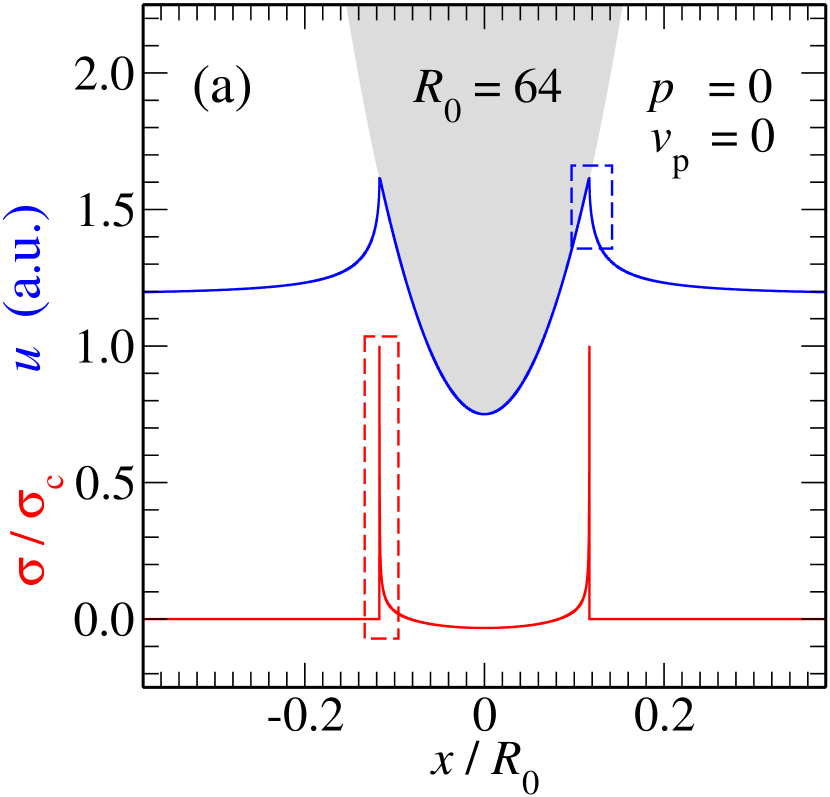
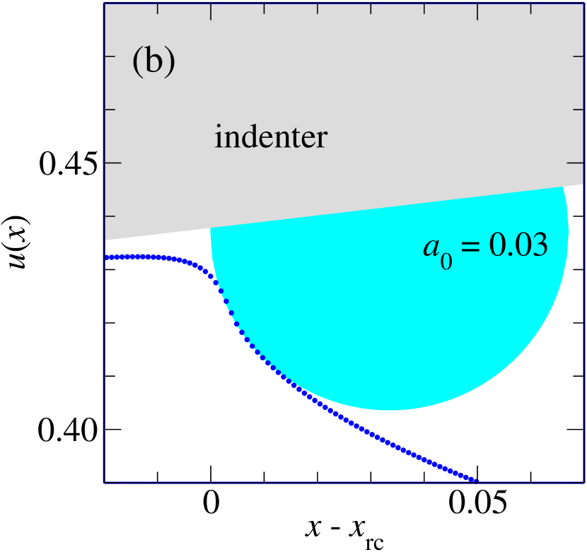
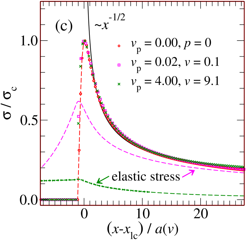
To further illuminate the model, Fig. 1(a) shows the overall contact geometry and the stress field for a force-free static contact and panel (b) a zoom into the displacement field showing our determination of the static crack-tip radius . Moreover, Fig. 1(c), see also Fig. S2 in SM, confirms that the interfacial stress in the vicinity of the crack tip obtained at different can be superimposed when scaling the distance from the crack tip with the ratio deduced from Eq. (1). For , the elastic stress, defined as the inverse Fourier transform of , coincides with . At intermediate , is still relatively close to in the immediate vicinity of the crack tip and approaches it asymptotically at large distances from the crack tip. However, elastic and interfacial stress differ substantially at large . Since relaxation is driven by the difference between elastic and interfacial stress, dissipation occurs predominantly far away from the cracks in the latter case.
Analytical results predict that the maximum tensile force, also called the pull-off force, , satisfies [22, 23, 24]. Treating the breaking of the adhesive bonds between the solids as the propagation of an opening interfacial crack also at the moment of pull-off, we therefore expect
| (6) |
where is the crack-tip velocity at the moment when the normal force reaches its maximum. In fact, Fig. 2 reveals close agreement between simulation and theory for how the pull-off force increases with pulling speed. The static pull-off forces, , needed to accurately normalize were deduced from mass-weighted GFMD simulations [29] using very small . They deviated at most by 0.1% from the just-stated, quasi-static continuum expression for .
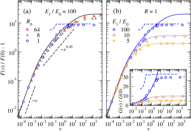
Persson-Brener theory (full lines in Fig. 2) match within the numerical precision in the linear-response regime at small velocities. This linear-response regime arises as a consequence of how the modeler (or nature!) discretizes the elastic manifold. For coarse discretization, lattice pinning occurs so that instabilities become unavoidable [30], which in turn lead to Coulomb friction. However, at fine discretization, “atoms” move continuously at all times under adiabatic driving and Stokes damping arises automatically. Power-law scaling of the damping force would only be expected down to infinitesimal small velocities right at the critical point (in the absence of thermal noise) separating the Stokes from the Coulomb regime [31]. There will still be extended velocity regimes, in which sub-linear small-velocity corrections to either or arise even if and thus ultimately cross over to Stokes, whenever stress singularity near crack tips extends down to small but not atomic scales.
Differences between Persson-Brener theory and simulations reach 30% at intermediate velocities and decrease again for large tip radii at large , where the viscoelastic fracture energy factor plateaus close to the predicted value of . The latter ratio can be directly deduced from the theory by combining Eqs. (1) to (3) and by realizing that . The close match between theory and simulation is an interesting result in its own right, also because the theory assumes steady-state crack propagation, while in reality, the crack-tip speed is not constant at fixed pull-off velocity. Moreover, even better agreement must be expected for systems with a broad distribution of relaxation times, as the sharp-wavenumber-cutoff approximation in the Persson-Brener approach should be most inaccurate for the three-element model with a single relaxation time.
Theory and simulation differ significantly in Fig. 2 for small tip radii when and are both large. This is due to the transition of the failure mode from crack propagation to quasi-uniform bond breaking, which was proposed to occur at small scales [20, 21]. The argument for the phenomenon is that the tensile load in a finite contact should be roughly limited by the product of the maximum tensile stress and the contact width . In fact, the dashed lines reflecting this estimate match the large-velocity limit for the , system quite well if the value for is the one observed in the simulations at the moment of maximum tensile force.
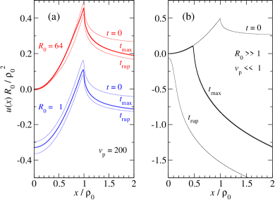
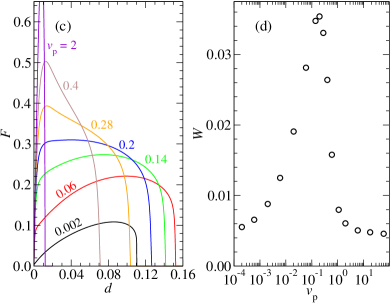
The suggested quasi-uniform bond breaking is also borne out from the displacement fields shown in Fig. 3(a): at large , the contact evidently fails by crack propagation while the displacement field moves almost homogeneously during failure for . Specifically, for contact is already lost at when the force reaches its maximum, while for , there is still contact near the origin directly after the moment of final rupture, which we define as the point in time right at which the tensile-load displacement curve assumes its most negative slope. At small velocities, all contacts studied here break in a similar way as shown for large in Fig. 3(b). This is because the Tabor parameter is greater than unity even for so that the adiabatic tip retraction is close to the continuum limit [32, 33].
The blue, dashed lines in Fig. 2 also reveal that the slope of the critical width , defined as the width of the contact at the moment of maximum force, changes discontinuously at a certain crack-tip velocity, which, however, is unrelated to the transition in the failure mode. Similar discontinuities in occur for all investigated systems. As no theory apparently predicts this transition, all currently existing analytical approaches to the crack-tip problem could be argued to be approximate.
To further illuminate the pull-off dynamics, Fig. 3(c) shows various load-displacement curves for . Their shape changes indeed abruptly near , for which has a very flat maximum. At that pull-off velocity, —the vertical distance moved to reach the maximum force—changes quite quickly from a value of order to , where the CZM assumes its maximum tensile stress.
Owing to the small forces needed to separate surfaces adiabatically and the small needed to break the contact at large , the work of separation turns out small in both limits. In between, viscous dissipation is largest leading to a pronounced maximum in , which is shown in Fig. 3(d). It can be said to arise, because a tensile force close to acts over relatively large pulling distances. Similar trends are found for larger system size when keeping and all other parameters constant as well as for regular Hertzian tips, for which does not have logarithmic system-size corrections, see also Fig. S4 in SM. Also flat, circular punches show a maximum in at intermediate , since both high- and low-velocity separation are easily found to be times punch area, at least as long as the range of adhesion remains short-ranged even when the elastomer assumes its high-frequency modulus.
The maximum in might appear counterintuitive, since monotonically increases with . However, only a small fraction of the initial contact is broken when the normal force assumes its maximum at large pulling velocities. Past that point, the crack tip velocity can quickly increase with time, in particular right before snap-off, as revealed in Fig. S3 in SM, so that the viscoelastic crack-propagation theory, which assumes slowly changing crack-tip speeds, no longer holds. A maximum loosely related to ours in occurs in the work needed to roll a cylinder a unit distance over a viscoelastic half space as a function of rolling speed [34, 35].
Our calculation of the work of separation does not include the energy loss due to the (visco-) elastic coupling between the center-of-mass mode of the elastomer’s surface facing the indenter and its other surface, which is typically driven in laboratory experiments. However, only the work of separation due to finite is dissipated in the vicinity of the contact so that we expect pull-off induced near-surface heating to be largest at intermediate velocities. This effect should also hold for interfaces that are more complex than the one investigated here. For example, the product of maximum stress and the time during which nerves in the vicinity of hair roots are exposed to large forces should be maximal at intermediate pull-off velocities, which might explain the sudden, but quickly decaying pain that we experience when pulling off a bandage with an intermediate velocity.
MHM acknowledges useful discussions with Sergey Sukhomlinov and Christian Müller.
References
- [1] W. G. Knauss. A review of fracture in viscoelastic materials. International Journal of Fracture, 196(1-2):99–146, November 2015.
- [2] C. Creton and M. Ciccotti. Fracture and adhesion of soft materials: a review. Reports on Progress in Physics, 79(4):046601, March 2016.
- [3] A. N. Gent. Adhesion and strength of viscoelastic solids. Is there a relationship between adhesion and bulk properties? Langmuir, 12(19):4492–4496, January 1996.
- [4] B. N. J. Persson, O. Albohr, G. Heinrich, and H. Ueba. Crack propagation in rubber-like materials. Journal of Physics: Condensed Matter, 17(44):R1071–R1142, October 2005.
- [5] R. Villey, C. Creton, P.-P. Cortet, M.-J. Dalbe, T. Jet, B. Saintyves, S. Santucci, L. Vanel, D. J. Yarusso, and M. Ciccotti. Rate-dependent elastic hysteresis during the peeling of pressure sensitive adhesives. Soft Matter, 11(17):3480–3491, 2015.
- [6] L. Afferrante and G. Carbone. The ultratough peeling of elastic tapes from viscoelastic substrates. Journal of the Mechanics and Physics of Solids, 96:223–234, November 2016.
- [7] G. Han, M. Eriten, and C. R. Henak. Rate-dependent adhesion of cartilage and its relation to relaxation mechanisms. Journal of the Mechanical Behavior of Biomedical Materials, 102:103493, February 2020.
- [8] R. A. Schapery. A theory of crack initiation and growth in viscoelastic media. International Journal of Fracture, 11(1):141–159, February 1975.
- [9] R. A. Schapery. A theory of crack initiation and growth in viscoelastic media ii. approximate methods of analysis. International Journal of Fracture, 11(1):369–388, June 1975.
- [10] M. Barber, J. Donley, and J. S. Langer. Steady-state propagation of a crack in a viscoelastic strip. Physical Review A, 40(1):366–376, July 1989.
- [11] C.-Y. Hui, D.-B. Xu, and E. J. Kramer. A fracture model for a weak interface in a viscoelastic material (small scale yielding analysis). Journal of Applied Physics, 72(8):3294–3304, October 1992.
- [12] G. Haiat, M.C. Phan Huy, and E. Barthel. The adhesive contact of viscoelastic spheres. Journal of the Mechanics and Physics of Solids, 51(1):69–99, January 2003.
- [13] J. A. Greenwood. The theory of viscoelastic crack propagation and healing. Journal of Physics D: Applied Physics, 37(18):2557–2569, September 2004.
- [14] J. A. Greenwood. Viscoelastic crack propagation and closing with lennard-jones surface forces. Journal of Physics D: Applied Physics, 40(6):1769–1777, March 2007.
- [15] P. G. de Gennes. Soft adhesives. Langmuir, 12(19):4497–4500, January 1996.
- [16] L. B. Freund. Dynamic Fracture Mechanics. Cambridge Uni- versity Press, Cambridge, 1998.
- [17] B. N. J. Persson and E. A. Brener. Crack propagation in viscoelastic solids. Physical Review E, 71(3):036123, March 2005.
- [18] N. Rodriguez, P. Mangiagalli, and B. N. J. Persson. Viscoelastic crack propagation: Review of theories and applications. In G. Heinrich, R. Kipscholl, and R. Stocek, editors, Fatigue Crack Growth in Rubber Materials. Springer, Cham., 2020.
- [19] L. Afferrante and G. Violano. On the effective surface energy in viscoelastic hertzian contacts. arXiv, cond-mat.soft, 2107.03796.
- [20] B.N.J Persson. Nanoadhesion. Wear, 254(9):832–834, May 2003.
- [21] H. Gao and H. Yao. Shape insensitive optimal adhesion of nanoscale fibrillar structures. Proceedings of the National Academy of Sciences, 101(21):7851–7856, May 2004.
- [22] M. Barquins. Adherence and rolling kinetics of a rigid cylinder in contact with a natural rubber surface. The Journal of Adhesion, 26(1):1–12, July 1988.
- [23] M. K. Chaudhury, T. Weaver, C. Y. Hui, and E. J. Kramer. Adhesive contact of cylindrical lens and a flat sheet. Journal of Applied Physics, 80(1):30–37, July 1996.
- [24] T. Liu, A. Jagota, and C.-Y. Hui. Adhesive contact of a rigid circular cylinder to a soft elastic substrate – the role of surface tension. Soft Matter, 11(19):3844–3851, 2015.
- [25] A. Wang, Y. Zhou, and M. H. Müser. Modeling adhesive hysteresis. Lubricants, 9(2):17, February 2021.
- [26] N. Prodanov, W. B. Dapp, and M. H. Müser. On the contact area and mean gap of rough, elastic contacts: Dimensional analysis, numerical corrections, and reference data. Tribology Letters, 53(2):433–448, December 2014.
- [27] R. Bugnicourt, P. Sainsot, N. Lesaffre, and A. A. Lubrecht. Transient frictionless contact of a rough rigid surface on a viscoelastic half-space. Tribology International, 113:279–285, September 2017.
- [28] S. V. Sukhomlinov and M. H. Müser. On the viscous dissipation caused by randomly rough indenters in smooth sliding motion. arXiv, cond-mat.soft, 2104.15056 (submitted to Applied Surface Science Advances).
- [29] Y. Zhou, M. Moseler, and M. H. Müser. Solution of boundary-element problems using the fast-inertial-relaxation-engine method. Physical Review B, 99(14):144103, April 2019.
- [30] D. Holland and M. Marder. Ideal brittle fracture of silicon studied with molecular dynamics. Physical Review Letters, 80(4):746–749, January 1998.
- [31] M. H. Müser. Nature of mechanical instabilities and their effect on kinetic friction. Physical Review Letters, 89(22):224301, November 2002.
- [32] D. Maugis. Adhesion of spheres: The JKR-DMT transition using a dugdale model. Journal of Colloid and Interface Science, 150(1):243–269, April 1992.
- [33] M. H. Müser. Single-asperity contact mechanics with positive and negative work of adhesion: Influence of finite-range interactions and a continuum description for the squeeze-out of wetting fluids. Beilstein Journal of Nanotechnology, 5:419–437, April 2014.
- [34] S. C. Hunter. The rolling contact of a rigid cylinder with a viscoelastic half space. Journal of Applied Mechanics, 28(4):611–617, December 1961.
- [35] J. S. van Dokkum and L. Nicola. Green’s function molecular dynamics including viscoelasticity. Modelling and Simulation in Materials Science and Engineering, 27(7):075006, August 2019.