Fault-tolerant operation of a logical qubit in a diamond quantum processor
Abstract
Solid-state spin qubits are a promising platform for quantum computation and quantum networks awschalom2018quantum ; chatterjee2021semiconductor . Recent experiments have demonstrated high-quality control over multi-qubit systems bradley2019ten ; nguyen2019quantum ; bourassa2020entanglement ; mkadzik2021precision ; he2019two ; xue2021computing , elementary quantum algorithms van2012decoherence ; van2019multipartite ; vorobyov2020quantum ; xue2021computing and non-fault-tolerant error correction unden_quantum_2016 ; waldherr_quantum_2014 ; cramer_repeated_2016 . Large-scale systems will require using error-corrected logical qubits that are operated fault-tolerantly, so that reliable computation is possible despite noisy operations preskill_reliable_1998 ; gottesman_stabilizer_1997 ; aliferis2005quantum ; terhal_quantum_2015 . Overcoming imperfections in this way remains a major outstanding challenge for quantum science preskill_reliable_1998 ; nickerson_topological_2013 ; nigg_quantum_2014 ; egan2020fault ; linke2017fault ; rosenblum2018fault ; campagne2020quantum ; andersen2020repeated ; marques2021logical ; chen2021exponential . Here, we demonstrate fault-tolerant operations on a logical qubit using spin qubits in diamond. Our approach is based on the 5-qubit code with a recently discovered flag protocol that enables fault-tolerance using a total of seven qubits chao2018 ; chamberland2018flag ; chao2020PRXQ . We encode the logical qubit using a novel protocol based on repeated multi-qubit measurements and show that it outperforms non-fault-tolerant encoding schemes. We then fault-tolerantly manipulate the logical qubit through a complete set of single-qubit Clifford gates. Finally, we demonstrate flagged stabilizer measurements with real-time processing of the outcomes. Such measurements are a primitive for fault-tolerant quantum error correction. While future improvements in fidelity and the number of qubits will be required, our realization of fault-tolerant protocols on the logical-qubit level is a key step towards large-scale quantum information processing based on solid-state spins.
Large-scale quantum computers and quantum networks will require quantum error correction to overcome inevitable imperfections gottesman_stabilizer_1997 ; preskill_reliable_1998 ; aliferis2005quantum ; terhal_quantum_2015 ; nickerson_topological_2013 . The central idea is to encode each logical qubit of information into multiple physical data qubits. Non-destructive multi-qubit measurements, called stabilizer measurements, can then be used to identify and correct errors gottesman_stabilizer_1997 ; preskill_reliable_1998 ; aliferis2005quantum ; terhal_quantum_2015 . If the error rates of all the components are below a certain threshold, it becomes possible to perform arbitrarily large quantum computations by encoding into increasingly more physical qubits preskill_reliable_1998 ; aliferis2005quantum ; terhal_quantum_2015 . A crucial requirement is that all logical building blocks, including the error-syndrome measurement, must be implemented fault tolerantly. At the lowest level, this implies that any single physical error should not cause a logical error.
Over the last years, steps towards suppressing errors through fault-tolerant quantum error correction have been made in various hardware platforms such as superconducting qubits rosenblum2018fault ; campagne2020quantum ; andersen2020repeated ; marques2021logical ; chen2021exponential , trapped-ion qubits nigg_quantum_2014 ; negnevitsky2018repeated ; egan2020fault , spin qubits in silicon xue2021computing ; he2019two ; mkadzik2021precision , and spin qubits in diamond waldherr_quantum_2014 ; cramer_repeated_2016 . Pioneering experiments have demonstrated codes that can detect but not correct errors Takita2017 ; linke2017fault ; andersen2020repeated ; marques2021logical , as well as non-fault-tolerant quantum error correction protocols that could correct some, but not all, types of errors knill_benchmarking_2001 ; waldherr_quantum_2014 ; nigg_quantum_2014 ; cramer_repeated_2016 ; chen2021exponential ; gong2021experimental ; campagne2020quantum . A recent experiment with trapped-ion qubits has demonstrated the fault-tolerant operation of an error correction code, albeit through destructive stabilizer measurements and post processing egan2020fault .
In this work, we realize fault-tolerant encoding, gate operations and non-destructive stabilizer measurements for a logical qubit of a quantum error correction code. Our logical qubit is based on the 5-qubit code, and we use a total of seven spin qubits in a diamond quantum processor (Fig. 1). Fault-tolerance is made possible through the recently discovered paradigm of flag qubits chao2018 ; chamberland2018flag ; chao2020PRXQ . First, we demonstrate a novel fault-tolerant encoding protocol based on repeated multi-qubit measurements which herald the successful preparation of the logical state. Then, we realize a complete set of transversal single-qubit Clifford gates. Finally, we demonstrate stabilizer measurements on the logical qubit and include a flag qubit to ensure compatibility with fault-tolerance. Our stabilizer measurements are non-destructive, the post measurement state is available in real time, and we use feedforward based on the measurement outcomes. These results demonstrate the key principles of fault-tolerant quantum error correction in a solid-state spin-qubit processor.
The logical qubit
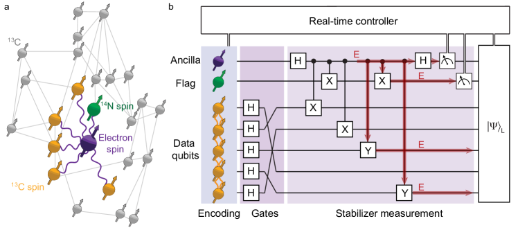
Stabilizer error correction codes use ancilla qubits to perform repeated stabilizer measurements that identify errors. A key requirement for fault-tolerance is to prevent errors on the ancilla qubits from spreading to the data qubits and causing logical errors (Fig. 1b) terhal_quantum_2015 ; chao2018 . The paradigm of flag fault-tolerance provides a solution with minimal qubit overhead chao2018 ; chamberland2018flag ; chao2020PRXQ . Ancilla errors that would cause logical errors are detected using additional flag qubits, so that they can be subsequently corrected (Fig. 1b).
Our logical qubit is based on the 5-qubit code, the smallest distance-3 code which can correct any single-qubit error laflamme_1996 ; knill_benchmarking_2001 . Any logical state is a simultaneous eigenstate of the four stabilizers , , , and , and the logical operators are and . Because any error on a single data qubit corresponds to a unique 4-bit syndrome, given as the eigenvalues of the stabilizers, arbitrary single-qubit errors can be identified and corrected. Combined with an ancilla qubit for stabilizer measurements and a flag qubit to capture harmful ancilla errors, this makes fault-tolerant error correction possible using 7 qubits in total chao2018 .
System: spin qubits in diamond
Our processor consists of a single nitrogen-vacancy (NV) centre and its surrounding nuclear spin environment at 4 Kelvin (Fig. 1a). These spins are high-quality qubits with coherence times up to seconds for the NV electron spin abobeih2018one and minutes for the nuclear spins bradley2019ten . The NV electron spin can be read out optically, couples strongly to all other spins, and is used as an ancilla qubit for stabilizer measurements (Methods) cramer_repeated_2016 ; bradley2019ten . We use the intrinsic 14N nuclear spin as the flag qubit. In this device, 27 13C nuclear-spin qubits and their lattice positions have been characterized, so that the 406 qubit-qubit interactions are known abobeih2019atomic . Each 13C qubit can be controlled individually due to their distinct couplings to the NV electron spin (Methods). Here, we use five of the 13C spin qubits as the data qubits to encode the logical qubit.
A challenge for controlling such a quantum processor is that the spins continuously couple to each other. We realize selective control gates through various echo sequences that isolate interactions between the targeted spins, while also protecting them from environmental decoherence. For all two-qubit gates, we use previously developed electron-nuclear gates, which are based on decoupling sequences on the electron spin (Methods) bradley2019ten . Furthermore, we introduce interleaved and asynchronous echo stages that cancel unwanted couplings between the data qubits (Methods). These additional echo stages are essential for the relatively long gate sequences realized here.
Non-destructive stabilizer measurements
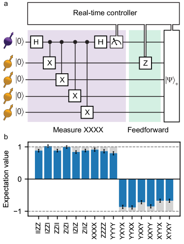
We start by demonstrating non-destructive 4-qubit stabilizer measurements with real-time feedforward operations based on the measurement outcomes (Fig. 2). Despite the central role of such measurements in many error-correction codes gottesman_stabilizer_1997 ; preskill_reliable_1998 ; aliferis2005quantum ; terhal_quantum_2015 , including the 5-qubit code, the Steane code and the surface code terhal_quantum_2015 , experimental implementations with feedforward have remained an outstanding challenge.
We benchmark the measurement by using it to deterministically create a 4-qubit entangled state. We prepare the state and measure the operator . This projects the qubits into the GHZ state , with the sign determined by the measurement outcome. We process the measurement outcomes in real time using a microprocessor and apply the required correction to deterministically output the state with a fidelity of . Because this result is obtained without any post-selection, it highlights that the post-measurement state is available for all measurement outcomes, satisfying one of the key requirements for error correction.
Fault-tolerant encoding
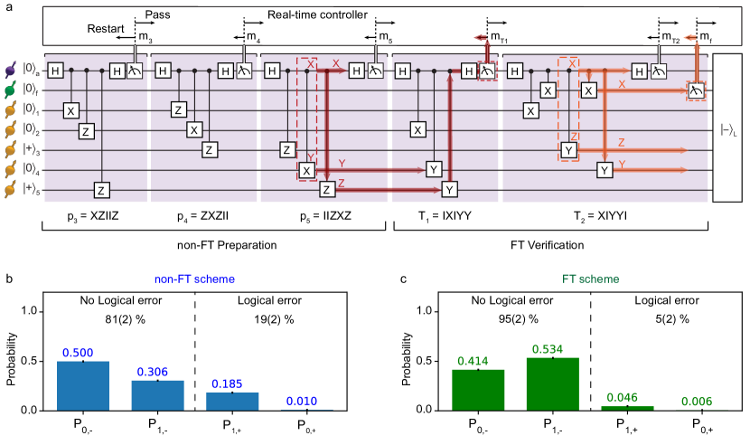
To prepare the logical qubit, we introduce a novel scheme that uses repeated stabilizer measurements and a flag qubit to herald successful preparation (Fig. 3a). In particular, we demonstrate the preparation of the logical state . This state is the unique eigenstate of 5 independent weight-3 logical operators namely , , , , . Therefore, one can prepare by initializing the data qubits into the product state , which is an eigenstate of and , and subsequently measuring to (Fig. 3a). This preparation scheme is not fault-tolerant because faults involving the ancilla qubit can cause weight-2 errors, which can result in logical errors (Fig. 3a). We refer to these steps as the non-FT encoding scheme.
We make the preparation circuit fault-tolerant by adding two stabilizer measurements, and with a flag qubit (Fig. 3a). Successful preparation is heralded by the following conditions: (1) the measurement outcomes of and are compatible with the measurement outcomes of the logical operators , i.e. and ; (2) the flag is not raised (i.e., the flag qubit is measured to be in ).
Otherwise the state is rejected. Further details and a proof of the fault-tolerance of this scheme are given in the Supplementary Information. We refer to this preparation as the FT encoding scheme.
To reduce the impact of ancilla measurement errors cramer_repeated_2016 ; van2019multipartite , we additionally require all stabilizer measurement outcomes to be (i.e., the NV electron spin is measured to be in ). These outcomes are more reliable (see Methods) bradley2019ten , increasing the fidelity of the state preparation, at the cost of a lower success probability (Supplementary Table 1).
We compare the non-FT and FT encoding schemes. We define the logical state fidelity as (see Methods)
| (1) |
where is the prepared state, and is the set of all single-qubit Pauli errors. The fidelity gives the probability that there is at most a single-qubit error in the prepared state, i.e. there is no logical error. We characterize the prepared state by tomographically measuring the 31 operators that define the target state (Supplementary Fig. 7 and Methods). We find that the FT encoding scheme () outperforms the non-FT scheme ().
To understand this improvement, we analyze the underlying error probability distributions (Figs. 3b,c). For the 5-qubit code, the state plus any number of Pauli errors is equivalent to either with at most one Pauli error (no logical error), or to with at most one Pauli error (a logical error). We calculate the overlaps between the prepared state and those states. The results show that the FT scheme suppresses logical errors, consistent with fault-tolerance preventing single faults propagating to multi-qubit errors. The overall logical state fidelity is improved, despite the higher probability of single-qubit errors due to the increased complexity of the sequence.
Fault-tolerant logical gates
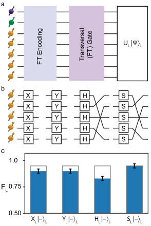
The 5-qubit code supports a complete set of transversal single-qubit Clifford gates, which are naturally fault-tolerant gottesman_stabilizer_1997 ; Yoder_2016 . We apply four transversal logical gates to (Fig. 4): , , the Hadamard gate , and the phase gate , where is a permutation of the data qubits (see Fig. 4b) gottesman_stabilizer_1997 ; Yoder_2016 . These permutations are fault-tolerant because we realize them by relabelling the qubits rather than by using SWAP gates Yoder_2016 .
Our control system performs the underlying single-qubit gates by tracking basis rotations and compiling them with subsequent gates or measurements (Methods). In the sequence considered here (Fig. 4a), such compilation does not increase the physical operation count, and there is no reduction of fidelity (Fig. 4c). For comparison, we also implement the ‘worst-case’ scenario where the logical gates are applied physically (Fig. 4c). This includes 5 single-qubit gates and the corresponding additional echo sequences between the state preparation and the measurement stage. Together, the demonstrated transversal logical gates enable the fault-tolerant preparation of all six eigenstates of the logical Pauli operators.
Fault-tolerant stabilizer measurements
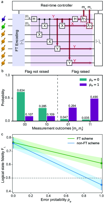
Finally, we demonstrate and characterize a flagged stabilizer measurement on the encoded state (Fig. 5a). Such measurements are a primitive for fault-tolerant quantum error correction protocols chao2018 . To ensure that the measurement is compatible with fault-tolerance, the two-qubit gates are carefully ordered and a flag qubit is added to capture ancilla errors that can propagate to logical errors chao2018 .
We prepare the logical state and measure the stabilizer (Fig. 5a). The resulting output consists of the post-measurement state and two classical bits of information from the ancilla and flag measurements (Fig. 5b). The logical state fidelity is given by the probability that the logical information can be correctly extracted (no logical error), when taking into account the flag measurement outcome. The interpretation of the error syndrome changes if the flag is raised (Methods). We find for the post measurement state without any post-selection. Higher logical state fidelities can be obtained by post-selecting on favourable outcomes, but this is incompatible with error correction.
To illustrate the benefit of the flag qubit we compare the logical state fidelities with and without taking the flag measurement outcome into account. Because ancilla errors that propagate to logical errors are naturally rare, no significant difference is observed (Fig. 5c). Therefore, we introduce a Pauli error on the ancilla qubit (Fig. 5a). This error propagates to the 2-qubit error . For the case without flag information, this error causes a logical flip (Methods), and the logical state fidelity drops below 0.5. In contrast, with the flag qubit, this non-trivial error is detected (Fig. 5b) and remains correctable, so that the logical state fidelity is partly recovered (Fig. 5c).
Conclusion
In conclusion, we have demonstrated encoding, gates and non-destructive stabilizer measurements for a logical qubit of an error correction code in a fault-tolerant way. Such fault-tolerant operations are a necessity for large-scale quantum computation in which error rates ultimately must be suppressed to extremely low levels.
Future challenges are to perform complete quantum error correction cycles, encode multiple logical qubits, realize universal fault-tolerant gates, and ultimately suppress logical error rates exponentially below physical error rates. While the demonstrated operations are of high fidelity—the experiments consist of up to 40 two-qubit gates and 8 mid-circuit ancilla readouts (Fig. 5a)—improvements in both the fidelities and the number of qubits will be required.
Improved gates might be realized through tailored optimal control schemes that leverage the precise knowledge of the system and its environment (Fig. 1a) dolde_high-fidelity_2014 . Coupling to optical cavities can further improve readout fidelities bhaskar2020experimental ; awschalom2018quantum . Scaling to large code distances and multiple logical qubits can be realized through already-demonstrated magnetic dolde_high-fidelity_2014 and optical pompili2021realization NV-NV connections that enable modular, distributed, quantum computation based on the surface code and other error correction codes nickerson_topological_2013 . Therefore, our demonstration of the building blocks of fault-tolerant quantum error correction is a key step towards quantum information processing based on solid-state spin qubits.
Methods
Sample.
We use a naturally occurring NV centre in a homo-epitaxially chemical-vapor-deposition (CVD) grown diamond with a natural abundance of 13C and a crystal orientation (grown by Element Six). A solid-immersion lens is used to enhance the photon-collection efficiency Robledo_Nature2011 . The NV center has been selected for the absence of 13C spins with hyperfine couplings 500 kHz. These experiments are performed at a temperature of 4 K where the electron-spin relaxation is negligible (s abobeih2018one ).
Qubits and coherence times. The NV electron-spin ancilla qubit is defined between the states () and (). The NV electron-spin coherence times are s, ms, and up to seconds under dynamical decoupling abobeih2018one . The 14N nuclear-spin flag qubit is defined between the states () and (). The 13C nuclear-spin data qubits in this device have been characterized in detail in previous work (Fig. 1a) abobeih2019atomic ; bradley2019ten ; jung2020deep . See Supplementary Tables 2-5 for the hyperfine parameters, coherence times, and qubit-qubit interactions for the qubits used here.
Magnetic field. A magnetic field of G is applied using a room-temperature permanent magnet on a XYZ translation stage. This applied field lifts the degeneracy of the states due to the Zeeman term (Supplementary Information). We stabilise the magnetic field to 3 mG using temperature stabilisation and an automatic re-calibration procedure (every few hours). We align the magnetic field along the NV axis using thermal echo sequences with an uncertainty of degrees in the alignment abobeih2019atomic .
Single- and two-qubit gates. Single-qubit gates and echo pulses are applied using microwave pulses for the NV electron spin ( transition, Hermite pulse shapes abobeih2018one ; warren1984effects , Rabi frequency of MHz) and using radio-frequency pulses for the 13C spin qubits (error function pulse shapes bradley2019ten , typical Rabi frequency of Hz) and the 14N spin qubit (error function pulse shapes, Rabi frequency kHz). The 13C spin qubits (data qubits) are distinguishable in frequency due to their hyperfine coupling to the NV electron spin (Supplementary Table 2).
Electron-nuclear two-qubit gates are realised using two different gate designs, depending on the properties of the targeted nuclear spin. For data qubits 1,2,4,5, two-qubit gates are realized through dynamical decoupling sequences of equally spaced -pulses on the electron spin of the form ( taminiau_universal_2014 ; bradley2019ten . This design requires a significant hyperfine component perpendicular to the applied magnetic field taminiau_universal_2014 . For data qubit 3 and the flag qubit (the 14N spin) the perpendicular hyperfine coupling is small and we perform two-qubit gates by interleaving the dynamical decoupling sequence with RF pulses bradley2019ten . Both gate designs simultaneously decouple the NV electron spin from the other qubits and the environment bradley2019ten . The parameters and fidelities for the two-qubit gates are given in Supplementary Table 4
Compilation of gate sequences. Our native two-qubit gates are electron-controlled nuclear-spin rotations and are equivalent to the CNOT gate up to single-qubit rotations (Supplementary Fig. 3). To implement the sequences shown in the figures, we first translate all gates into these native gates and compile the resulting sequence.
Echo sequences for the data qubits. To mitigate decoherence of the data qubits due to their spin environment, we use echo sequences that are interleaved throughout the experiments. These echo sequences ensure that the data qubits rephase each time they are operated on. Additionally, the sequence design minimizes the time that the ancilla electron spin is idling in superposition states, which are prone to dephasing. We use two echo stages between stabilizer measurements, as well as before and after the logical gates of Fig. 4, which provides a general and scalable solution for the timing of all gates and echoes (Supplementary Information).
An additional challenge is that, due to the length of the sequences (up to 100 ms), we need to account for the small unwanted interactions between the nuclear-spin data qubits. The measured coupling strengths show that the strongest couplings are between qubits 3 and 2 (16.90(4) Hz, and between qubits 3 and 5 (12.96(4) Hz) (Supplementary Table 5) abobeih2019atomic ). Such interactions can introduce correlated two-qubit errors that are not correctable in the distance-3 code considered here, which can only handle single-qubit errors in the code block.
To mitigate these qubit-qubit couplings, we decouple qubit 3 asynchronously from the other qubits (Supplementary Fig. 5). Ultimately, such local correlated errors can be suppressed entirely by larger distance codes.
Real-time control and feedforward operations. Real-time control and feedforward operations are implemented through a programmable microprocessor (Jaeger ADwin Pro II) operating on microsecond timescales. The microprocessor detects photon events coming from the detectors, infers the measurement outcomes, and controls both the subsequent sequences in the arbitrary waveform generator (Tektronix AWG 5014c) and the lasers for the ancilla qubit readout. The precise timing for quantum gates ( nanosecond precision) is based on the clock of the arbitrary waveform generator. Additionally, the microprocessor operates various control loops that prepare the NV center in the negative charge state, on resonance with the lasers, and in the focus of the laser beam (see Supplementary Information).
Readout of the ancilla qubit. The electron spin (ancilla qubit) is read out by resonantly exciting the to optical transition Robledo_Nature2011 . For one or more photons detected we assign the outcome, for zero photons we assign . The single-shot readout fidelities are and for and , respectively (average fidelity: ).
Uncontrolled electron-spin flips in the excited state cause dephasing of the nuclear spins through the hyperfine interaction. To minimize such spin flips we avoid unnecessary excitations by using weak laser pulses, so that a feedback signal can be used to rapidly turn off the laser upon detection of a photon (within 2 s). The resulting probability that the electron spin is in state after correctly assigning in the measurement is 0.992 cramer_repeated_2016 .
For measurements that are used for heralded state preparation, i.e. where we only continue upon a outcome (see e.g. Fig. 3), we use shorter readout pulses. This improves the probability that a outcome correctly heralds the state, at the cost of reduced success probability (see Supplementary Table 1).
System preparation and qubit initialization. At the start of the experiments we first prepare the NV center in its negative charge state and on resonance with the lasers. We then initialize the NV electron spin in the state through a spin pumping process (Fidelity ) Robledo_Nature2011 . We define the electron-spin qubit between the states and . We initialize the data qubits through SWAP sequences (Supplementary Fig. 4) into , and subsequent optical reset of the ancilla qubit (initialization fidelities , see Supplementary Table 4). The flag qubit is initialized through a projective measurement that heralds preparation in (initialization fidelity ). Other product states are prepared by subsequent single qubit gates.
Final readout of the data qubits. Tomographically measuring single- and multi-qubit operators of the data qubits is performed by mapping the required correlation to the ancilla qubit (through controlled rotations) and then reading out the ancilla qubit cramer_repeated_2016 . In order to provide best estimates for the measurements, we correct the measured expectation values (Fig. 2 and Supplementary Figs. 6,7) for infidelities in the readout sequence, see Bradley et al. bradley2019ten for the correction procedure.
Assessing the logical state fidelity. The logical state fidelity is defined in Eq. (1) and gives the probability that the state is free of logical errors. Said differently, is the fidelity with respect to the ideal 5-qubit state after a round of perfect error correction, or the probability to obtain the correct outcome in a perfect fault-tolerant logical measurement. While fault-tolerant circuits for logical measurement exist chao2018 , we do not experimentally implement these here. Instead, we extract from a set of tomographic measurements, as described in the following using as an example.
The logical state is the unique simultaneous eigenstate of the 5 weight-3 operators with eigenvalue . We can thus describe the state (with a Pauli error) as the projector
where is the measurement outcome of , and when anti-commutes with . This projector can be expanded as a summation of 31 multi-qubit Pauli operators (including a constant), which are listed in Supplementary Fig. 7. The logical state fidelity in Eq. (1) can then be written as
| (2) |
Here is the set of correctable errors for the 5-qubit code. To obtain experimentally, we measure this set of expectation values.
Logical state fidelity with flag. If the flag in the circuit in Fig. 5a is not raised, then a cycle of error correction would correct any single-qubit error on a logical state. The logical state fidelity is then given by Eq. (1), which we now refer to as . A raised flag leads to a different interpretation of the error syndrome (Supplementary Table 7) chao2018 .
For example, the error on ancilla in Fig. 5a leads to the output state , for which the eigenvalues of give the syndrome . Without flag, the corresponding single-qubit recovery is , which changes the syndrome back to all (Supplementary Table 7). This recovery leads to the remaining error , which is a logical error. However, taking the flag measurement outcome into account, the syndrome is interpreted differently and the recovery is so that no error is left (Supplementary Table 7).
For the cases where the flag is raised, the logical state fidelity with respect to is now given by:
| (3) |
with another set of correctable errors
| (4) |
A detailed derivation for this set of errors and their corresponding syndromes are given in the Supplementary Information.
The logical state fidelity after the stabilizer measurement (Fig. 5) is calculated as the weighted sum of the fidelities conditioned on the two flag outcomes:
| (5) |
with the probability that the flag is raised and and are defined above.
Finally, to construct the logical state fidelity as a function of (Fig. 5c), we measure with () and without () the ancilla error and calculate the outcomes for other error probabilities from their weighted sum:
| (6) |
Error distribution in the prepared state. The overlaps between the prepared state and the state with identity or a single-qubit error are written as and , respectively. These correspond to the cases that there is no logical error. The overlaps between the prepared state and the state with identity or a single-qubit error are written as and , respectively. In these cases there is a logical error. These overlaps are shown in Fig. 3b,c and calculated as ()
| (7) |
| (8) |
Acknowledgements. This work was supported by the Netherlands Organisation for Scientific Research
(NWO/OCW) through a Vidi grant and the Quantum Software Consortium programme (Project No. 024.003.037/3368). This project has received funding from the European Research Council (ERC) under the European Union’s Horizon 2020 research and innovation programme (grant agreement No. 852410). We gratefully acknowledge support from the joint research program “Modular quantum computers” by Fujitsu Limited and Delft University of Technology, co-funded by the Netherlands Enterprise Agency under project number PPS2007. This project (QIA) has received funding from the European Union’s Horizon 2020 research and innovation programme under grant agreement No 820445. This work was supported by a QuantERA grant for the QCDA consortium.
Note added. While finalizing this manuscript two related pre-prints appeared that demonstrate destructive stabilizer measurements with a flag qubit hilder2021fault , and flag fault-tolerant quantum error correction ryan2021realization with trapped-ion qubits.
Data availability.
The data that support the findings of this study are available from the corresponding author upon request.
Author contributions.
MHA, YW, and THT devised the experiments. MHA performed the experiments and collected the data. YW and BMT developed the fault-tolerant preparation scheme and its analysis. MHA, YW, JR, BMT, and THT analyzed the data. MHA, JR, SJHL and CEB prepared the experimental apparatus. MM and DJT grew the diamond sample. MHA, YW and THT wrote the manuscript with input from all authors. BMT and THT supervised the project.
References
- (1) Awschalom, D. D., Hanson, R., Wrachtrup, J. & Zhou, B. B. Quantum technologies with optically interfaced solid-state spins. Nat. Photon. 12, 516–527 (2018).
- (2) Chatterjee, A. et al. Semiconductor qubits in practice. Nat. Rev. Phys. 3, 157–177 (2021).
- (3) Bradley, C. E. et al. A ten-qubit solid-state spin register with quantum memory up to one minute. Phys. Rev. X 9, 031045 (2019).
- (4) Nguyen, C. et al. Quantum network nodes based on diamond qubits with an efficient nanophotonic interface. Phys. Rev. Lett. 123, 183602 (2019).
- (5) Bourassa, A. et al. Entanglement and control of single nuclear spins in isotopically engineered silicon carbide. Nat. Mater. 19, 1319–1325 (2020).
- (6) Mkadzik, M. T. et al. Precision tomography of a three-qubit electron-nuclear quantum processor in silicon. Preprint at https://arxiv.org/abs/2106.03082 (2021).
- (7) He, Y. et al. A two-qubit gate between phosphorus donor electrons in silicon. Nature 571, 371–375 (2019).
- (8) Xue, X. et al. Computing with spin qubits at the surface code error threshold. Preprint at https://arxiv.org/abs/2107.00628 (2021).
- (9) Van der Sar, T. et al. Decoherence-protected quantum gates for a hybrid solid-state spin register. Nature 484, 82–86 (2012).
- (10) van Dam, S. B., Cramer, J., Taminiau, T. H. & Hanson, R. Multipartite entanglement generation and contextuality tests using nondestructive three-qubit parity measurements. Phys. Rev. Lett. 123, 050401 (2019).
- (11) Vorobyov, V. et al. Quantum fourier transform for quantum sensing. Preprint at https://arxiv.org/abs/2008.09716 (2020).
- (12) Unden, T. et al. Quantum Metrology Enhanced by Repetitive Quantum Error Correction. Phys. Rev. Lett. 116, 230502 (2016).
- (13) Waldherr, G. et al. Quantum error correction in a solid-state hybrid spin register. Nature 506, 204–207 (2014).
- (14) Cramer, J. et al. Repeated quantum error correction on a continuously encoded qubit by real-time feedback. Nat. Commun. 7, 11526 (2016).
- (15) Preskill, J. Reliable quantum computers. Proc. R. Soc. A 454, 385–410 (1998).
- (16) Gottesman, D. E. Stabilizer Codes and Quantum Error Correction. Ph.D. thesis, California Institute of Technology (1997).
- (17) Aliferis, P., Gottesman, D. & Preskill, J. Quantum accuracy threshold for concatenated distance-3 code. Quantum Inf. Comput. 6, 97–165 (2006).
- (18) Terhal, B. M. Quantum error correction for quantum memories. Rev. Mod. Phys. 87, 307–346 (2015).
- (19) Nickerson, N. H., Li, Y. & Benjamin, S. C. Topological quantum computing with a very noisy network and local error rates approaching one percent. Nat. Commun. 4, 1756 (2013).
- (20) Nigg, D. et al. Quantum computations on a topologically encoded qubit. Science 345, 302–305 (2014).
- (21) Egan, L. et al. Fault-tolerant operation of a quantum error-correction code. Preprint at https://arxiv.org/abs/2009.11482 (2020).
- (22) Linke, N. M. et al. Fault-tolerant quantum error detection. Sci. Adv. 3, e1701074 (2017).
- (23) Rosenblum, S. et al. Fault-tolerant detection of a quantum error. Science 361, 266–270 (2018).
- (24) Campagne-Ibarcq, P. et al. Quantum error correction of a qubit encoded in grid states of an oscillator. Nature 584, 368–372 (2020).
- (25) Andersen, C. K. et al. Repeated quantum error detection in a surface code. Nat. Phys. 1–6 (2020).
- (26) Marques, J. et al. Logical-qubit operations in an error-detecting surface code. Preprint at https://arxiv.org/abs/2102.13071 (2021).
- (27) AI, G. Q. Exponential suppression of bit or phase errors with cyclic error correction. Nature 595, 383–387 (2021).
- (28) Chao, R. & Reichardt, B. W. Quantum error correction with only two extra qubits. Phys. Rev. Lett. 121, 050502 (2018).
- (29) Chamberland, C. & Beverland, M. E. Flag fault-tolerant error correction with arbitrary distance codes. Quantum 2, 53 (2018).
- (30) Chao, R. & Reichardt, B. W. Flag fault-tolerant error correction for any stabilizer code. PRX Quantum 1, 010302 (2020).
- (31) Abobeih, M. H. et al. Atomic-scale imaging of a 27-nuclear-spin cluster using a quantum sensor. Nature 576, 411–415 (2019).
- (32) Negnevitsky, V. et al. Repeated multi-qubit readout and feedback with a mixed-species trapped-ion register. Nature 563, 527–531 (2018).
- (33) Takita, M., Cross, A. W., Córcoles, A. D., Chow, J. M. & Gambetta, J. M. Experimental demonstration of fault-tolerant state preparation with superconducting qubits. Phys. Rev. Lett. 119, 180501 (2017).
- (34) Knill, E., Laflamme, R., Martinez, R. & Negrevergne, C. Benchmarking Quantum Computers: The Five-Qubit Error Correcting Code. Phys. Rev. Lett. 86, 5811–5814 (2001).
- (35) Gong, M. et al. Experimental exploration of five-qubit quantum error correcting code with superconducting qubits. Natl. Sci. Rev. (2021).
- (36) Laflamme, R., Miquel, C., Paz, J. P. & Zurek, W. H. Perfect quantum error correcting code. Phys. Rev. Lett. 77, 198–201 (1996).
- (37) Abobeih, M. H. et al. One-second coherence for a single electron spin coupled to a multi-qubit nuclear-spin environment. Nat. Commun. 9, 2552 (2018).
- (38) Yoder, T. J., Takagi, R. & Chuang, I. L. Universal fault-tolerant gates on concatenated stabilizer codes. Phys. Rev. X 6, 031039 (2016).
- (39) Dolde, F. et al. High-fidelity spin entanglement using optimal control. Nat. Commun. 5, 3371 (2014).
- (40) Bhaskar, M. K. et al. Experimental demonstration of memory-enhanced quantum communication. Nature 580, 60–64 (2020).
- (41) Pompili, M. et al. Realization of a multinode quantum network of remote solid-state qubits. Science 372, 259–264 (2021).
- (42) Robledo, L. et al. High-fidelity projective read-out of a solid-state spin quantum register. Nature 477, 574–578 (2011).
- (43) Jung, K. et al. Deep learning enhanced individual nuclear-spin detection. npj Quantum Information 7, 1–9 (2021).
- (44) Warren, W. S. Effects of arbitrary laser or nmr pulse shapes on population inversion and coherence. J. Chem. Phys 81, 5437–5448 (1984).
- (45) Taminiau, T. H., Cramer, J., Sar, T. v. d., Dobrovitski, V. V. & Hanson, R. Universal control and error correction in multi-qubit spin registers in diamond. Nat. Nanotech. 9, 171–176 (2014).
- (46) Hilder, J. et al. Fault-tolerant parity readout on a shuttling-based trapped-ion quantum computer. Preprint at https://arxiv.org/abs/2107.06368 (2021).
- (47) Ryan-Anderson, C. et al. Realization of real-time fault-tolerant quantum error correction. Preprint at https://arxiv.org/abs/2107.07505 (2021).