Magneto Optical Sensing beyond the Shot Noise Limit
Abstract
Magneto-optical sensors including spin noise spectroscopies and magneto-optical Kerr effect microscopies are now ubiquitous tools for materials characterization that can provide new understanding of spin dynamics, hyperfine interactions, spin-orbit interactions, and charge-carrier g-factors. Both interferometric and intensity-difference measurements can provide photon shot-noise limited sensitivity, but further improvements in sensitivity with classical resources require either increased laser power that can induce unwanted heating and electronic perturbations or increased measurement times that can obscure out-of-equilibrium dynamics and radically slow experimental throughput. Proof-of-principle measurements have already demonstrated quantum enhanced spin noise measurements with a squeezed readout field that are likely to be critical to the non-perturbative characterization of spin excitations in quantum materials that emerge at low temperatures. Here, we propose a truncated nonlinear interferometric readout for low-temperature magneto-optical Kerr effect measurements that is accessible with today’s quantum optical resources. We show that 10 sensitivity is achievable with optical power as small as 1 W such that a realistic = 83 mK can be maintained in commercially available dilution refrigerators. The quantum advantage for the proposed measurements persists even in the limit of large loss and small squeezing parameters.
I Introduction
Discovered in 1844, the Faraday effect describes the circular birefringence of light transmitted through a medium. Since then, magneto-optical effects have become the cornerstone of several families of characterization techniques. Faraday and Kerr (reflection) rotation measurements are now ubiquitous tools for characterizing magnetism at microscopic to interstellar length scales [1, 2]. Magneto-optical spin noise measurements have been demonstrated with broadband radio-frequency readout[3, 4], and Sagnac-interferometric magneto-optical spectroscopies have been employed to discriminate various time-parity symmetries[5]. While magneto-optical spectroscopies are now a workhorse for materials characterization, state-of-the-art measurements are still limited by the photon shot noise limit (SNL). The signal to noise ratio of such shot-noise-limited measurements scales with the square root of the laser power and the readout time, but this becomes an issue when non-perturbative measurements are desired and when probing a delicate quantum mechanical state at mK temperatures [6]. For instance, shot-noise-limited magneto-optical Kerr effect (MOKE) measurements offer sensitivity of order with 10 of laser power[7]. Resolving 10 nanoradian polarization rotation then requires either 1 mW of laser power with a 1 s measurement or 10 of laser power with a 100 s measurement, or some alternative balance between increased power and increased measurement time. Increased power will introduce substantial unwanted heating in low temperature measurements. Longer measurement times make experiments substantially more challenging, particularly as sensitivity requirements continue to increase.
In 1981, C.M. Caves showed that squeezed states of light enable sensitivity beyond the SNL in interferometric measurements [8]. Thirty years later, squeezed light is now an important resource for quantum sensing for a wide range of applications[9, 10, 11], with examples ranging from gravitational wave detection [12, 13] to plasmonic sensing[14, 15, 16, 11] to scanning probe microscopies [17, 18, 9], magnetometry[19, 20, 21, 22], Raman spectroscopy[23, 24, 25], and spin noise spectroscopy [26, 27]. Nonlinear interferometry, in which beamsplitters are replaced with nonlinear amplifiers, has also drawn interest in recent years as an alternative to conventional quantum sensing with squeezed states [28, 29, 30, 31]. These interferometric sensors can be designed to concentrate losses into the local oscillators, thus minimizing the detrimental effects of loss on squeezing. In addition, careful local oscillator (LO) design eliminates the need to tightly control spatial modes that proves troublesome in quantum sensors relying on multi-spatial-mode squeezed light sources [32, 17]. Nonlinear interferometry offers the potential to outperform classical interferometers by a factor proportional to the nonlinear gain of the amplifier [28, 29, 30], and its benefit can be traced to the amount of squeezing present in the nonlinear amplifier.
Recent experiments have shown that truncated nonlinear interferometers can be used to characterize the displacement of atomic-force-microscope microcantilevers without introducing excessive heating[18]. Such experiments take advantage of the squeezing generated by a nonlinear amplifier while minimizing laser induced heating by utilizing low-power or vacuum squeezed states together with high power local oscillators. Because the shot noise level is defined by the total power at the detector, including local oscillator power, unwanted photomodification and heating of the sample can be minimized without sacrificing the quantum advantage. A growing literature now describes the sensitivity of nonlinear [29, 30, 33] and truncated nonlinear interferometers [34, 35, 36]. Here, we define the fundamental limits of magneto-optical spectroscopies based on Faraday and Kerr rotation of light with classical readout fields, and we show how two-mode squeezed light can be used to obtain quantum enhanced sensitivity beyond classical limits. In a phase sensing configuration, the device corresponds to a truncated nonlinear interferometer. We characterize the effect of non-ideal homodyne detectors by incorporating a second-quantization treatment of the LOs. We find that, though the uncertainty of the polarization rotation measurement decreases fastest when both the probe and the probe LO power increase simultaneously, substantial quantum enhancement is still possible with vacuum or low power squeezed readout fields. This lays the foundation for ultra-low temperature magneto-optical spectroscopies.
II Polarization sensing with truncated SU(1, 1) interferometers
The squeezed MOKE described here centers on truncated SU(1, 1) interferometry (tSU(1, 1)), wherein we transduce the MOKE polarization rotation on a two-mode squeezed state to an optical phase shift and we readout that change in phase with dual homodyne detection. However, we note that this by no means the only approach. Quantum-enhanced polarization measurements with polarization-squeezed states of light have been carried out by Lucivero et al. for instance [26]. By transducing the polarization rotation to an optical phase shift, the signal becomes immune to polarization fluctuations in optics downstream before the detector. This is particularly beneficial in implementations utilizing free-space optical components that are polarization sensitive. For instance dielectric mirrors that help to minimize the loss in the optics train induce unwanted polarization rotation that is hard to correct for in the absence of the polarization to phase transduction described here and utilized in existing classical MOKE Sagnac interferometers[7].
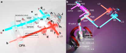
Figure 1 shows the proposed optical circuit. The inset illustrates a schematic for the MOKE tSU(1, 1) interferometer considered in this work. The interferometer consist of an optical parametric amplifier (OPA) that generates a two mode squeezed state, a MOKE microscope that induces a polarization rotation on the probe and conjugate beams generated by the OPA, a quarter-wave plate that converts that polarization rotation to a phase shift, and dual homodyne detectors that read out that phase shift. The OPA is characterized by a squeezing parameter (gain ). The a, b, c, d, e, f, g, h, , , , and are optical field operators, with a, b serving as the two OPA input modes. After the probe (conjugate) is mixed with the LO g (h), the modes and ( and ) are detected by a balanced photodetector. Beamsplitter interactions are included with efficiency and to allow for optical losses and in the probe and conjugate arms respectively and to allow for excess noise c and d to be coupled into each arm.
The polarization rotation can be transduced into a phase shift with two quarter-wave plates (QWPs) sandwiching the sample of interest. The first QWP converts the linearly polarized light field into circularly polarized light. Due to the Faraday effect in the sample, linearly polarized light acquires a polarization rotation while circularly polarized light field acquires a phase shift. The second QWP then converts the circularly polarized light back to linearly polarized light. The resulting phase shift of the light after this optical circuit is , where is the phase for an . This results in a 1:1 transduction of the polarization rotation into a phase shift. Since for any optical element that can be described by a member of SU(2), and , can be described by a product of two QWPs and a half wave plate (HWP) [37], the three real degrees of freedom for can be separately transduced to a phase shift. Though we focus on polarization rotation in cryogenic MOKE microscopies here, the same result can be extended to measurements of the ellipticity and circularity of light.
For the probe homodyne detector, the two outputs can be expressed as
| (1) | ||||
where m is the input field into the homodyne-detector beamsplitter coming from the sample. The intensity difference measurement can be written as af†af - an†an. A similar expression can be written for the conjugate arm. With the optical circuit shown in Figure 1 and with the simplification , the resulting joint rotated quadrature measurement operator is:
| (2) |
where . The uncertainty of the polarization rotation measurement with respect to measurement is [34, 38]:
| (3) |
III Limit of detection improvement
To quantify the quantum enhancement of the signal to noise ratio, we consider a classical interferometer with both the arms interacting with the sample (Supplementary Information). The photon numbers are normalized to the photon numbers in the case of tSU(1, 1), i.e., probe arm has , conjugate arm has , and their LOs have and , respectively. We define our limit of detection (LOD) equivalent to Anderson et al. [34] :
| (4) |
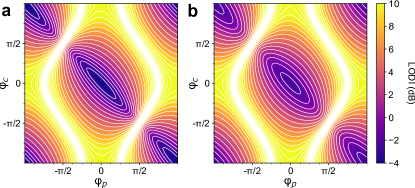
The LOD can then be calculated analytically with the following starting values: (or for a wavelength of 794 nm). LO (or 10 mW for the same wavelength). Initially, we define a conservative squeezing parameter of corresponding to gain G = 3.0 dB. With these values and only the probe photons interacting with the sample, the limit of detection improvement (LODI) ( = LODtSU(1,1) LODclassical) is dB, or dB when both the probe and the conjugate interact with the sample. For high precision numeric evaluation beyond complex256 data type, Python package mpmath[39] was used. Figure 3 (a) compares the resulting LODI for a truncated SU(1, 1) interferometer against a classical interferometer for polarization rotation sensing, as a function of and , the phases of probe and conjugate LOs . The optimal setting for and is a function of and occurs at (rad), (rad) for (rad). When , the basin of the contour becomes more flat, as shown in Figure 3 (b) with and the LODI deteriorates to 2.374 dB.
IV Dependence on Experimental Parameters
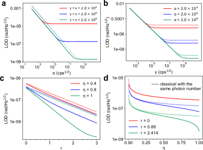
Figure 4 is a collection of LOD for tSU(1, 1) and classical interferometer as a function of various experimental parameters from , , and . Dashed plots are the classical case with the same amount of photons interacting with the sample on both the probe and the conjugate arm and the same amount of photons at the LOs.
-
1.
. As shown in Figure 4 (a), the LOD improvement appears at lower and that advantage disappears as approaches . The advantage at low in fact extends all the way to , which is corresponding to seeding only the vacuum states into the OPA though LOD is ill-defined at . We revisit the vacuum seeding in the the next Section.
-
2.
. In 4 (b), as increases, the LOD starts to improve for the tSU(1, 1) over classical interferometer as and the slope of the improvement drastically decreases when and saturates when the shot noise from the LOs dominates the detectors.
-
3.
. In Figure 4 (c), the improvement in LOD starts at , but the margin decreases as decreases.
-
4.
. As in Figure 4 (d), at , the LOD for the tSU(1, 1) and the classical case conincide with each other. The LOD improvement started to be visible as as long as . As increases, the LOD becomes increasingly sensitive to , especially at the limit. For example, when (G = 15 dB) and , the LOD improvement is 5.29 dB. But with G = 20 dB at and , the LODI is only 5.41 dB.
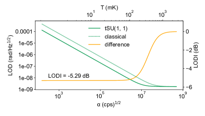
In order for magneto-optical microscopies to probe magnetic structure present in quantum materials at mK temperatures, the measurement must be non-perturbative; the laser readout should not heat the sample over a phase transition during the measurement. In order to understand the optimal sensitivity that can be achieved for a given probe photon number at mK temperatures, we modeled the temperature as a function of the probe photon number for the dilution refrigerator described in Ref. [6]. The system has cooling power of 1 mW at 100 mK at the mixing chamber plate, 200 W on the cold insertable probe, and less at the end of the cold finger, where the sample is mounted. Figure 5 illustrates the LOD and LODI as a function of and , with state-of-the-art squeezing parameter = 2.413 (G = 15 dB) and = 0.92 [40]. A consistent LODI of -5.29 dB extends to the low limit. At , the LODI is -5.27 dB, = 83 mK, and LOD 10 .
V Sensing with two mode squeezed vacuum
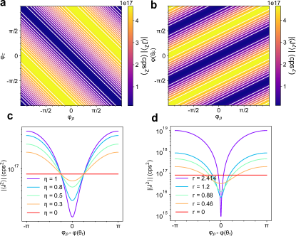
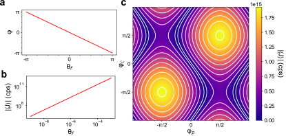
When neither of the two input ports of the OPA are seeded, the output of the OPA is a two mode squeezed vacuum. Though they individually are thermal states, the joint quadrature of the two exhibits quantum noise reduction as well as entanglement. It is therefore possible to be used for sensing. With the seeded photon , the vanishes as well as , where as and hence does not. Additionally, the resulting is a function of where if using the same transduction described earlier. This is not possible for the classical case, as the resulting does not depend on and only depends on the LO power. With one arm interacting with the sample, the is:
| (5) |
Figure 6 (a) represents as a function of and when , and Fig. 6 (b) represents as a function of and . has minima when and maxima when they are out of phase by . Figure 6 (c) represents as a function of at several values with . Figure 6 (d) represents as a function of at several values with . The quantum advantage for two-mode-squeezed-vacuum sensing exists as long as and . This makes the two mode squeezed vacuum extremely desirable for quantum sensing at extremely low-temperature, low-probe-power conditions.
VI Conclusion
In summary, we have described a clear path to quantum-enhanced MOKE at ultra low temperatures that is accessible with today’s quantum light sources. We have derived an analytical expression for the joint rotated quadrature detection operator for polarization rotation measurements using a tSU(1, 1) interferometer. We have shown that the tSU(1, 1) outperforms its classical counterpart MZI in polarization rotation measurements across the entire parameter space explored here. We further showed that the measurement can benefit from a strong LO when the probe photon number has to be limited to minimize heating. The calculation done here is automatically generated for any sample that can be described by an SU(2) group. The calculation for the Sagnac version is expect to hold the parity etc. The calculation here can be extended to the frequency domain via the dissipation fluctuation theorem. The treatment presented here assumed a single-spatial-mode squeezed light source, but it extends trivially to multi-spatial-mode squeezed light sources, which is critical to the detection of polar and longitudinal MOKE signals on segmented quadrant photodiodes. Thus, with today’s multi-spatial-mode squeezed light sources, it is possible to characterize polar and longitudinal MOKE signals with LOD 10 at temperatures of less than 100 mK.
Acknowledgements.
The connections between quantum sensing theory and condensed matter physics were sponsored by the U. S. Department of Energy, Office of Science, Basic Energy Sciences, Materials Sciences and Engineering Division. The foundations of the quantum sensing theory were supported by the U.S. Department of Energy, Office of Science, National Quantum Information Science Research Centers, Quantum Science Center. Postdoctoral (CEM) research support was provided by the Intelligence Community Postdoctoral Research Fellowship Program at the Oak Ridge National Laboratory, administered by Oak Ridge Institute for Science and Education through an interagency agreement between the U.S. Department of Energy and the Office of the Director of National Intelligence.Data Availability Statement
Data underlying the results presented in this paper may be obtained from the authors upon reasonable request.
References
- Jiang et al. [2013] W. Jiang, P. Upadhyaya, Y. Fan, J. Zhao, M. Wang, L.-T. Chang, M. Lang, K. L. Wong, M. Lewis, Y.-T. Lin, et al., “Direct imaging of thermally driven domain wall motion in magnetic insulators,” Physical Review Letters 110, 177202 (2013).
- Gray et al. [1998] A. D. Gray, T. L. Landecker, P. E. Dewdney, and A. R. Taylor, “A large-scale, interstellar faraday-rotation feature of unknown origin,” Nature 393, 660–662 (1998).
- Zapasskii [2013] V. S. Zapasskii, “Spin-noise spectroscopy: from proof of principle to applications,” Advances in Optics and Photonics 5, 131–168 (2013).
- Müller et al. [2010] G. M. Müller, M. Oestreich, M. Römer, and J. Hübner, “Semiconductor spin noise spectroscopy: Fundamentals, accomplishments, and challenges,” Physica E: Low-dimensional Systems and Nanostructures 43, 569–587 (2010).
- Kapitulnik et al. [2009] A. Kapitulnik, J. Xia, E. Schemm, and A. Palevski, “Polar kerr effect as probe for time-reversal symmetry breaking in unconventional superconductors,” New Journal of Physics 11, 055060 (2009).
- Lawrie et al. [2021] B. J. Lawrie, M. Feldman, C. E. Marvinney, and Y. Y. Pai, “Free-space confocal magneto-optical spectroscopies at millikelvin temperatures,” (2021), arXiv:2103.06851 [quant-ph] .
- Xia et al. [2006] J. Xia, P. T. Beyersdorf, M. M. Fejer, and A. Kapitulnik, “Modified sagnac interferometer for high-sensitivity magneto-optic measurements at cryogenic temperatures,” Applied Physics Letters 89, 062508 (2006).
- Caves [1981] C. M. Caves, “Quantum-mechanical noise in an interferometer,” Physical Review D 23, 1693–1708 (1981).
- Lawrie, Pooser, and Maksymovych [2020] B. Lawrie, R. Pooser, and P. Maksymovych, “Squeezing noise in microscopy with quantum light,” Trends in Chemistry 2, 683–686 (2020).
- Lawrie et al. [2019] B. J. Lawrie, P. D. Lett, A. M. Marino, and R. C. Pooser, “Quantum sensing with squeezed light,” ACS Photonics 6, 1307–1318 (2019).
- Lee et al. [2021] C. Lee, B. Lawrie, R. Pooser, K.-G. Lee, C. Rockstuhl, and M. Tame, “Quantum plasmonic sensors,” Chemical Reviews 121, 4743–4804 (2021).
- Aasi et al. [2013] J. Aasi, J. Abadie, B. Abbott, R. Abbott, T. Abbott, M. Abernathy, C. Adams, T. Adams, P. Addesso, R. Adhikari, et al., “Enhanced sensitivity of the ligo gravitational wave detector by using squeezed states of light,” Nature Photonics 7, 613 (2013).
- Ma et al. [2017] Y. Ma, H. Miao, B. H. Pang, M. Evans, C. Zhao, J. Harms, R. Schnabel, and Y. Chen, “Proposal for gravitational-wave detection beyond the standard quantum limit through epr entanglement,” Nature Physics 13, 776 (2017).
- Fan, Lawrie, and Pooser [2015] W. Fan, B. J. Lawrie, and R. C. Pooser, “Quantum plasmonic sensing,” Physical Review A 92, 053812 (2015).
- Dowran et al. [2018] M. Dowran, A. Kumar, B. J. Lawrie, R. C. Pooser, and A. M. Marino, “Quantum-enhanced plasmonic sensing,” Optica 5, 628–633 (2018).
- Pooser and Lawrie [2015a] R. C. Pooser and B. Lawrie, “Plasmonic trace sensing below the photon shot noise limit,” ACS Photonics 3, 8–13 (2015a).
- Pooser and Lawrie [2015b] R. C. Pooser and B. Lawrie, “Ultrasensitive measurement of microcantilever displacement below the shot-noise limit,” Optica 2, 393–399 (2015b).
- Pooser et al. [2020] R. Pooser, N. Savino, E. Batson, J. Beckey, J. Garcia, and B. Lawrie, “Truncated nonlinear interferometry for quantum-enhanced atomic force microscopy,” Physical Review Letters 124, 230504 (2020).
- Otterstrom, Pooser, and Lawrie [2014] N. Otterstrom, R. C. Pooser, and B. J. Lawrie, “Nonlinear optical magnetometry with accessible in situ optical squeezing,” Optics Letters 39, 6533–6536 (2014).
- Wolfgramm et al. [2010] F. Wolfgramm, A. Cere, F. A. Beduini, A. Predojević, M. Koschorreck, and M. W. Mitchell, “Squeezed-light optical magnetometry,” Physical Review Letters 105, 053601 (2010).
- Li et al. [2018] B.-B. Li, J. Bilek, U. B. Hoff, L. S. Madsen, S. Forstner, V. Prakash, C. Schäfermeier, T. Gehring, W. P. Bowen, and U. L. Andersen, “Quantum enhanced optomechanical magnetometry,” Optica 5, 850–856 (2018).
- Horrom et al. [2012] T. Horrom, R. Singh, J. P. Dowling, and E. E. Mikhailov, “Quantum-enhanced magnetometer with low-frequency squeezing,” Physical Review A 86, 023803 (2012).
- Michael et al. [2019] Y. Michael, L. Bello, M. Rosenbluh, and A. Pe’er, “Squeezing-enhanced raman spectroscopy,” npj Quantum Information 5, 1–9 (2019).
- de Andrade et al. [2020] R. B. de Andrade, H. Kerdoncuff, K. Berg-Sørensen, T. Gehring, M. Lassen, and U. L. Andersen, “Quantum-enhanced continuous-wave stimulated raman scattering spectroscopy,” Optica 7, 470–475 (2020).
- Casacio et al. [2021] C. A. Casacio, L. S. Madsen, A. Terrasson, M. Waleed, K. Barnscheidt, B. Hage, M. A. Taylor, and W. P. Bowen, “Quantum-enhanced nonlinear microscopy,” Nature 594, 201–206 (2021).
- Lucivero et al. [2016] V. G. Lucivero, R. Jiménez-Martínez, J. Kong, and M. W. Mitchell, “Squeezed-light spin noise spectroscopy,” Physical Review A 93, 053802 (2016).
- Wineland et al. [1992] D. J. Wineland, J. J. Bollinger, W. M. Itano, F. Moore, and D. Heinzen, “Spin squeezing and reduced quantum noise in spectroscopy,” Physical Review A 46, R6797 (1992).
- Hudelist et al. [2014] F. Hudelist, J. Kong, C. Liu, J. Jing, Z. Ou, and W. Zhang, “Quantum metrology with parametric amplifier-based photon correlation interferometers,” Nature Communications 5, 3049 (2014).
- Ou [2012] Z. Y. Ou, “Enhancement of the phase-measurement sensitivity beyond the standard quantum limit by a nonlinear interferometer,” Physical Review A 85, 023815 (2012).
- Jing et al. [2011] J. Jing, C. Liu, Z. Zhou, Z. Ou, and W. Zhang, “Realization of a nonlinear interferometer with parametric amplifiers,” Applied Physics Letters 99, 011110 (2011).
- Wang et al. [2021] H. Wang, Z. Fu, Z. Ni, X. Zhang, C. Zhao, S. Jin, and J. Jing, “Nonlinear interferometric surface-plasmon-resonance sensor,” Optics Express 29, 11194–11206 (2021).
- Treps et al. [2003] N. Treps, N. Grosse, W. P. Bowen, C. Fabre, H.-A. Bachor, and P. K. Lam, “A quantum laser pointer,” Science 301, 940–943 (2003).
- Anderson et al. [2017a] B. E. Anderson, B. L. Schmittberger, P. Gupta, K. M. Jones, and P. D. Lett, “Optimal phase measurements with bright- and vacuum-seeded su(1,1) interferometers,” Physical Review A 95, 063843 (2017a).
- Anderson et al. [2017b] B. E. Anderson, P. Gupta, B. L. Schmittberger, T. Horrom, C. Hermann-Avigliano, K. M. Jones, and P. D. Lett, “Phase sensing beyond the standard quantum limit with a variation on the su (1, 1) interferometer,” Optica 4, 752–756 (2017b).
- Gupta et al. [2018] P. Gupta, B. L. Schmittberger, B. E. Anderson, K. M. Jones, and P. D. Lett, “Optimized phase sensing in a truncated su (1, 1) interferometer,” Optics Express 26, 391–401 (2018).
- Prajapati and Novikova [2019] N. Prajapati and I. Novikova, “Polarization-based truncated su(1,1) interferometer based on four-wave mixing in rb vapor,” Opt. Lett. 44, 5921–5924 (2019).
- Simon and Mukunda [1990] R. Simon and N. Mukunda, “Minimal three-component su(2) gadget for polarization optics,” Physics Letters A 143, 165–169 (1990).
- Bachor and Ralph [2019] H. Bachor and T. Ralph, A Guide to Experiments in Quantum Optics (Wiley, 2019).
- Johansson et al. [2013] F. Johansson et al., mpmath: a Python library for arbitrary-precision floating-point arithmetic (version 0.18) (2013), http://mpmath.org/.
- Vahlbruch et al. [2016] H. Vahlbruch, M. Mehmet, K. Danzmann, and R. Schnabel, “Detection of 15 db squeezed states of light and their application for the absolute calibration of photoelectric quantum efficiency,” Phys. Rev. Lett. 117, 110801 (2016).