Improving Grasp Stability with Rotation Measurement
from Tactile Sensing
Abstract
Rotational displacement about the grasping point is a common grasp failure when an object is grasped at a location away from its center of gravity. Tactile sensors with soft surfaces, such as GelSight sensors, can detect the rotation patterns on the contacting surfaces when the object rotates. In this work, we propose a model-based algorithm that detects those rotational patterns and measures rotational displacement using the GelSight sensor. We also integrate the rotation detection feedback into a closed-loop regrasping framework, which detects the rotational failure of grasp in an early stage and drives the robot to a stable grasp pose. We validate our proposed rotation detection algorithm and grasp-regrasp system on self-collected dataset and online experiments to show how our approach accurately detects the rotation and increases grasp stability.
I INTRODUCTION
Robotic grasping is a long-studied problem and the foundation of many manipulation tasks [1]. Frequently-asked questions in robotic manipulation include how to grasp an arbitrary object stably, detect grasp failure promptly, and take precautions to avoid such failure. Traditional grasping research focused on detecting grasping locations based on the shape of the objects [2], [3] which is typically obtained from vision. However, those methods rarely considered objects’ physical properties, such as mass, mass distribution, surface friction, and rigidity. Such properties, which can attribute to significant differences in the physical interaction between robots and the target objects, are essential to decide the optimal grasps.
Tactile sensing provides promising solutions to the challenge. By detecting the contact area and contact force during grasping, tactile sensing gives effective feedback about the grasp outcome, which subsequently can be used to build a closed-loop grasping framework. The study of tactile-sensing-based grasp focuses on detecting and measuring slip [4], [5] to choose a proper grasping force to avoid object dropping. However, rotation is another common cause of grasp failure, that has not been well studied. This kind of failure happens when a robot grasps an object at locations far from the object’s center of gravity. As a result, the large torque at the contact can make the object rotate or make the grasp vulnerable to external impact. Increasing the gripping force does little to mitigate this type of failure. Instead, this problem can be corrected by choosing other grasp locations closer to the object’s center of gravity.
In this paper, we improve the grasp stability by proposing a model-based method to detect the rotation caused by torque using a tactile sensor. Our method can detect the rotational failure of grasp at an early stage and use tactile information to guide a robot to find a stable grasping location that is close to the object’s center of gravity. We apply our method to a vision-based tactile sensor called GelSight [6], which uses a piece of soft elastomer as the medium of contact and an embedded camera to track the deformation of the elastomer surface. The torque on the contact surface will cause torsion on the elastomer medium, which can be visualized as a rotational pattern of the markers painted on the elastomer surface. We measure the markers’ rotation angles and directions to estimate the torque, and show the stability of the grasp against the torsional load. Because our method is based on the physical feedback during the contact, it applies to a wide variety of arbitrary objects with unknown physical properties, such as mass distribution. With increased grasping stability, our method can help robots operate more robustly and reliably in real-world environments.
II RELATED WORK
II-A Grasping and Regrasping
Computer vision techniques have been employed in robotic manipulation tasks to synthesize grasp poses using visual data of objects and scenes either with model-based methods [7], [8] or learning-based methods [9], [10]. However, they do not infer the objects’ properties, such as mass distribution, friction coefficient, and rigidity. Lack of information of these properties can cause inaccurate or even incorrect grasping operations, which may further result in post-grasp effects like rotation, slippage, and even detachment from the gripper, which may ultimately lead to grasping failure. We use RGB-D data in our work to estimate the geometric center of the object as the initial grasping location and then use a tactile sensor’s feedback to adjust the grasp locations.
Tactile sensors can complement vision data by providing local information at the grasp location, such as measuring slippage [5], [11], force [12], grasp stability [13], [14], [15] and object’s Center of Mass (COM) [16], [17]. [9] combined tactile sensors with vision sensors to obtain better predictions of grasp outcomes using deep neural networks. [18] obtained grasp poses by probing a given workspace and localizing objects from tactile signals without using vision. [19] used tactile feedback to reduce uncertainty in contact position and orientation. However, grasp failure due to incorrect grasp locations is rarely studied using tactile sensors, and we address this problem through our work.
Regrasping has been used to improve grasp success rate by correcting grasp characteristics, such as pose and force, using feedback from additional sensors. In [20], the author proposed a method to simulate tactile images at different locations of the object from an initial grasp point, predict grasp success for each of these images, and choose the corresponding location with the highest predicted score for regrasping. [21] used a low-resolution pressure tactile sensor to detect grasp failure due to slip, and implemented an LSTM model trained on both tactile and force/torque data to sample a regrasp location achieving stable grasp. [22] solved a similar problem like ours to detect wrist moments when large objects are grasped at locations away from their COM. The aforementioned work used both force and torque information from a force/torque sensor to detect grasp instability and guide the robot towards the object’s COM. In our work, instead of using force/torque information, we detect similar instabilities in smaller household objects using only images from a tactile sensor.
II-B Slip Detection based on Tactile Sensing
One of the primary motivations of our work is the capability of tactile sensors to detect slippage. Several model-based [23], [24], [25] and learning-based [26], [27] methods have used tactile sensors to detect, classify and measure slip. Rotational slip can also result from an incorrect grasping location. Some early works such as [28] and [29] used force/torque tactile sensors to classify translational and rotational slip by analyzing contact area. [30] and [31] trained neural networks to classify linear and rotational slip from force/pressure sensor data and piezo-resistive sensor data. [32] discussed the concept of a contact centroid and proposed a method to obtain rotational spin about this point using remote force/torque sensor readings.
The GelSight sensor is a vision-based tactile sensor that provides high-resolution information of the contact region. When an object comes in contact with the gel, the gel surface deforms, and the markers on the gel undergo radial motion. By tracking these marker motions, users can study local phenomena like slippage and rotation in great detail. There have been some related studies [5], [33] to detect the occurrence of slip using Gelsight tactile sensors, but they are restricted to numerically identifying slip. We use the GelSight sensor in our analysis to track and analyze the rotational patterns of objects at the contact location. To the best of our knowledge, this is the first attempt at detecting rotation of objects and measuring rotation angle and its orientation using only a vision-based tactile sensor.
III METHOD
When grasping an object at a location away from the object’s center of gravity, the object undergoes rotation about the gripping point due to the moment applied by gravitational force. We show that it is possible to detect this rotation and measure it in real-time using images from the GelSight sensor. The GelSight sensor outputs tactile images with markers labeled on them. These markers trace the object’s movement when the sensor is in quasi-static contact with the object, hence providing high-resolution localized information in the contact region. When rotation occurs, it gives rotational patterns of markers on the GelSight surface. We analyze these patterns to determine the Center of Rotation (COR) and eventually calculate the rotation angle. We then show how this method can help a robot to reach a stable grasp pose.
III-A Contact Rotation Measurement Overview
Our algorithm proceeds through three steps: 1) Object Contact Detection: Initially, the system keeps looping to check the occurrence of contact between the sensor surface and the object. 2) Detection of Rotation Onset: It then tracks the markers on the GelSight image and keeps checking if rotational patterns occur on the surface. 3) Rotation Angle Measurement: If rotation starts, it then analyzes the marker motions and calculates the Center of Rotation(COR). The algorithm then gives a measure of the angle of rotation and its orientation about the calculated COR. The following subsections detail each step of the algorithm.
III-B Object Contact Detection
Precise contact detection is an essential pre-processing step for rotation detection. When a grasp occurs, the markers that contact the object can directly trace the objects’ motion. In the subsequent frames, these markers, designated as contact markers, can indicate whether the object undergoes rotation or remains stable. The remaining markers are designated as non-contact markers.
The grasping process takes time to complete and the contact area on the gel is dynamic. We first identify a stable contact state of the grasp and then the contact region in the image corresponding to it. To accommodate different situations, we determine a stable grasp state in two ways: soft stable contact and hard stable contact. After 10 frames from the start, if the change in the frame-frame markers’ motion magnitude is less than a set threshold, we say the contact is a soft stable contact. However, in some cases, there is hardly a stable contact stage and we designate the frame after 30 frames(1sec) as the hard stable contact.
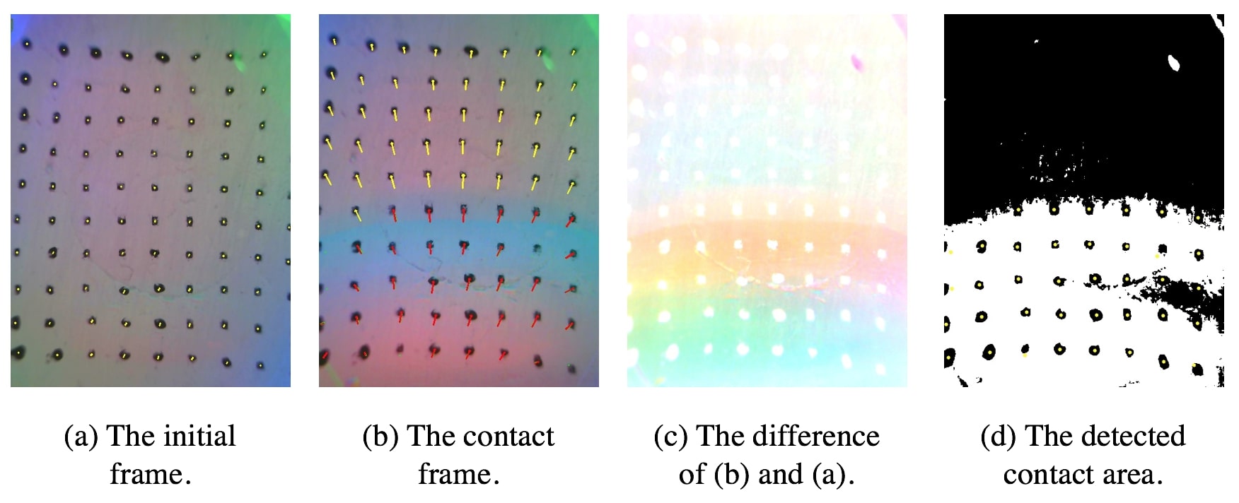
By the time the contact becomes stable, the illumination changes across the three color channels as seen in Fig. 2(a) and Fig. 2(b). We take the maximum of illumination change across R, G, and B channels at all pixel locations, as in Fig. 2(c), and then filter the resulting image to get the contact region as in Fig. 2(d).
III-C Detection of Rotation Onset
After detecting contact, the algorithm tries to identify the markers’ rotational patterns in the subsequent frames. If no such patterns are detected, the grasp is considered stable. Otherwise, we process the patterns to measure rotational displacement.
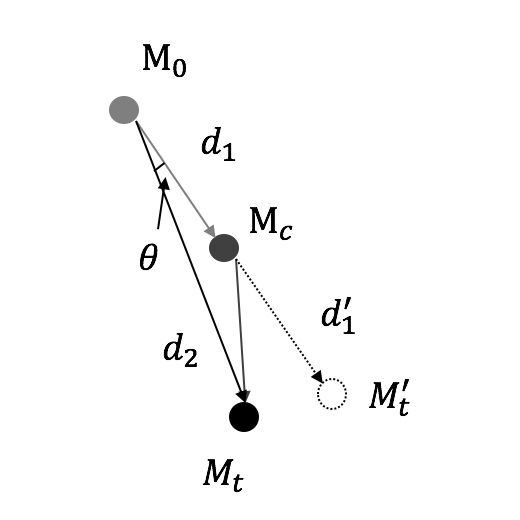
We calculate the relative motion change and angular change of the marker vectors w.r.t contact markers in any given frame after contact. If either of these changes crosses a fixed threshold, we say that the object is in rotation. The object’s translational motion will be considered separately in the following sections. For instance, in Fig. 3(a), for a certain marker, we check the value of angle between the motion from the initial frame to the stable contacting frame as and the motion from the initial frame to the current frame as . We check the magnitude of the motion from the stable contact frame to the current frame as well. If one of them goes beyond a threshold, we consider that as the onset of rotation, and start to measure the rotation angle.
III-D Rotation Angle Measurement
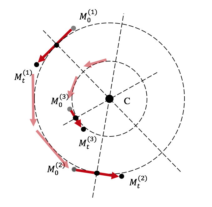
In this step, we detect the location of the center of rotation (COR) and measure rotational displacement about this center. We take the motion of markers from the initial frame and draw normals to each of them. The intersection point of these normal vectors would ideally be the COR. However, due to noise, they might not intersect at a single location. Hence, we formulate a least-squares solution to obtain the best estimation of COR.
Illustrated in Fig. 3(b), assuming the COR is , and one motion vector is from to , then the motion vector is perpendicular to the direction joining the COR and the mid point of the motion vector . Under the ideal situation with no sensor noise, the perpendicularity can be satisfied as
| (1) |
Therefore, the best estimation of COR can be solved with a set of motion vectors by forming in normal equation as
| (2) |
And the rotation center C is estimated by
| (3) |
The angle of rotation is calculated as the angle of
:
| (4) |
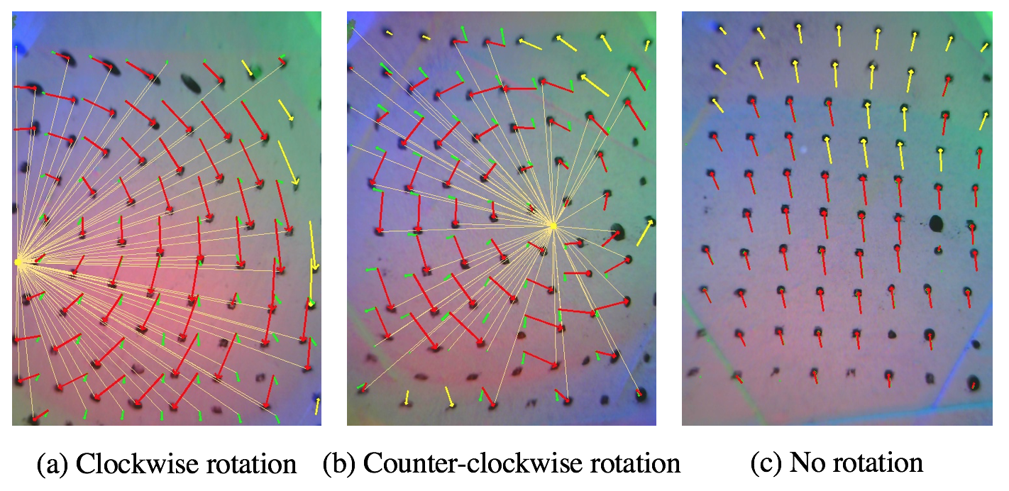
However, the angle calculated for each maker is an absolute rotation angle value, which does not have direction. We calculate the orientation of rotation by taking the moment of the motion w.r.t the COR. If the sign of the moment is positive, it is counter-clockwise and clockwise if negative.
The nature of the gel and its interaction with the objects can result in noise with some markers exhibiting orientation in the opposite direction to the object’s rotation direction. Therefore, we calculate the moments about COR for all the markers and do a majority vote to decide the final orientation of rotation. If a rotation occurs, one orientation group should dominate the others. However, if an object is grasped and remains static, it could be recognized as a rotation case due to the markers’ radial motion. In such a scenario, the number of markers in both groups are similar, which can distinguish false-positive cases from the real rotation cases with dominant numbers as described above.
Clockwise rotation and counter-clockwise rotation cases can be seen in Fig. 4(a) and (b), where we find the CORs for contact markers. A grasp can be considered stable in two cases: 1) no rotation of the object occurs, 2) low rotation with small rotation angles, set as 5∘ in our experiments.
III-E Special Cases
III-E1 Translational Displacement
One special case is the translational displacement during grasping. When the gripper lifts the object, the object undergoes translational movement due to the imbalance of friction and gravity if there is insufficient normal contact force. It is natural to increase the normal force [5] to avoid this displacement. Markers’ motion are mostly similar in direction for translation and dissimilar for rotation. We utilize this fact to distinguish between translational and rotational displacement in our analysis. We apply SVD decomposition on the motion of markers. If there is only one dominating direction, which reflects in only one large singular value, we say the motion is translation.
III-E2 Small Contact Area
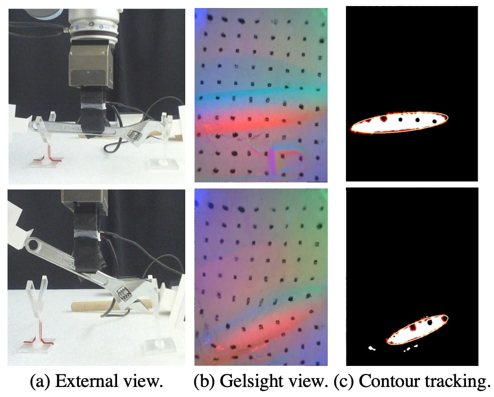
Another special case is when the contact happens only in a small area with objects that have irregular shapes. As seen in Fig. 5(b), the contact area is not flat but small with rich geometry, so it is hard to track markers inside the contact area. Alternatively, we measure the rotation by locating and tracking the contact area’s contour. Specifically, we track the relative angular change of the contour’s principal axis because the rotation of the area can be approximated by the rotation of the principal axis. Based on the construction of the tactile sensor, the lights come from the surrounding of the gel pad. So the contact area with huge gradients’ color value is more intense. We convert the RGB format into HSV format, filter and smooth the Value channel to extract the main contact area as shown in Fig. 5(c).
III-F Closed-loop control based on rotation measurement
We build a regrasp control framework to utilze the GelSight feedback to find a stable grasp position of an object. We setup an RGB-D camera to estimate the object’s size as a reference for regrasping adjustment step size.
III-F1 Object Size Estimation
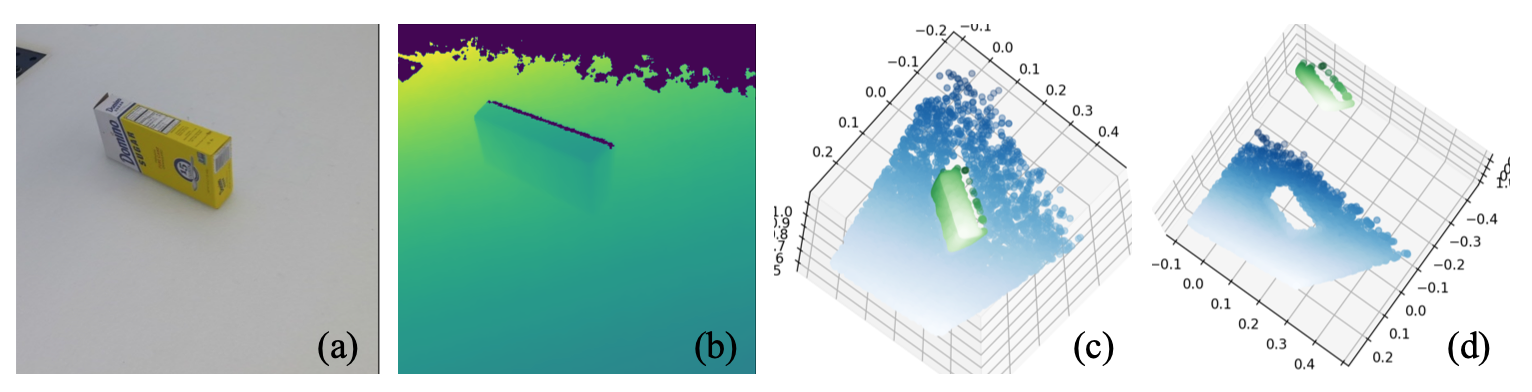
We use the real-scale point cloud generated from the RGB-D data to estimate the object’s size, as shown in Fig. 6. Given our experimental setting, where the background is a clean and flat table plane, the plane and the object can be segmented out with RANSAC simultaneously. We only estimate the length of the principal axis along the object because the gripper moves along that axis. To find the principal axis, we project the 3D point cloud of the object to the 2D table plane found from the RANSAC, and apply SVD decomposition to find the principal axis with the largest singular value which is the long axis. We take the 95% longest distance to the center point as the half of length to tolerate the potential outliers in the point cloud.
III-F2 Closed-loop Control
With the object’s length measured from vision, we design the regrasp algorithm as following. First, the robot starts with an initial grasp near the geometric center of object. If that grasp is ascertained as rotation, the robot will release the object and move along the object’s principal axis to the updated grasp location. The initial regrasp step size is , and then reduced to for the later regrasps. The initial and adjusted step sizes are heuristic but this configuration is verified to be effective in the experiments where the robot could reach a stable grasp pose in a few steps. If the rotation orientation changes during two regrasps, it means that the robot has passed the Center of Gravity. The robot then takes the updated step in the backward direction, and we know that the Center of Gravity is between the two grasp locations. We will then further reduce the step size by a factor of 0.5 for a finer adjustment. With this coarse-to-fine grasp adjustment design, our algorithm can quickly find the Center of Gravity within a few grasp trials.
IV EXPERIMENTS
We conduct two sets of experiments: offline grasp experiments on contact rotation detection, and closed-loop regrasp experiments based on the rotation measurement results. In the offline experiments, we grasp and lift different objects at different points in a dataset and then evaluate our rotation measurement algorithm by comparing against the ground truth. In the closed-loop regrasp experiments, we integrate the feedback of the GelSight sensor to update grasp locations until a stable grasp is attained.
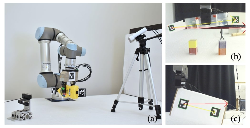
We set up a 6 DOF robot arm (UR5e by Universal Robots) and a parallel jaw gripper (WSG50 by Weiss) to perform grasps. We mount a GelSight sensor on one side and a 3D printed finger(PLA) on the other side. An Azure Kinect camera faces the object from a top view. We then place an external USB camera on the object’s side view to obtain ground truth of objects’ rotation angles and orientation. The setup is shown in Fig. 8 (a).
IV-A Contact Rotation Measurement on Offline Data
Dataset Collection: We collect data about the rotation of objects to test the rotation detection algorithm’s performance. Data includes time-synchronized image sequences from both the GelSight sensor and an external USB camera. The USB camera is placed on the object’s side view to capture the Aruco markers and further measure the rotation of the objects as the ground truth. As illustrated in the Fig. 8 (b) and (c), two Aruco markers are attached parallel to the object’s long axis. Under this setting, the rotation is 2D on the plane of the Aruco markers. This is consistent with the rotational displacement detected from the Gelsight, which is attached on a parallel gripper where only 2D rotational displacements take place in between. Given the real size of the Aruco markers and intrinsic parameters of the camera, the pose of Aruco markers can be estimated using the Perspective-n-Point (PnP) algorithm. We set the initial direction from one marker to another in the first frame, and then calculate the direction change on the Aruco markers’ plane as the rotation ground truth for the following frames. If the algorithm detects rotation and the angle measurement is above 5∘, we consider it an unstable grasp.
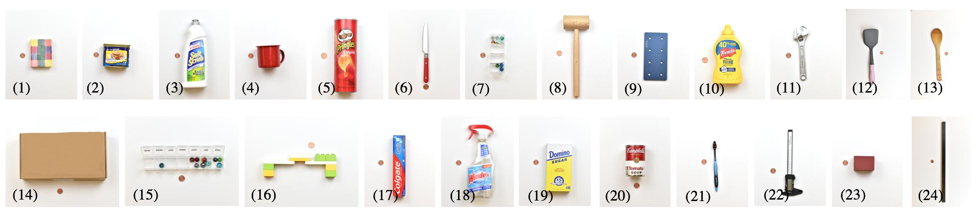
We perform 142 grasps on the first 14 objects, as seen in Fig. 7, at multiple locations with gripping speeds varying from 30-50 mm/s and a gripping force of 30 N. The robot goes uniformly over different locations on the objects along their centroidal axis and grasps at each point. At each grasp, the robot lifts the object upwards to a height of 5 cm and places it back. While the robot lifts the objects, the GelSight sensor and the external USB camera record images at 30 fps. In total, we collected 142 grasp data points with 98 of them labeled as rotational cases and 44 labelled as stable grasps, including translational slip cases using Aruco markers’ relative positions.
Accuracy of rotation detection: We compare the measured rotation angles from the GelSight images with the ground truth of objects’ rotation measured from the external camera. Some examples are shown in Fig. 9. The positive value of angles in the diagrams represent clockwise rotation, and negative values represent counter-clockwise rotation. We also evaluate the rotation onset detection delay which can be seen as vertical lines in the figures.
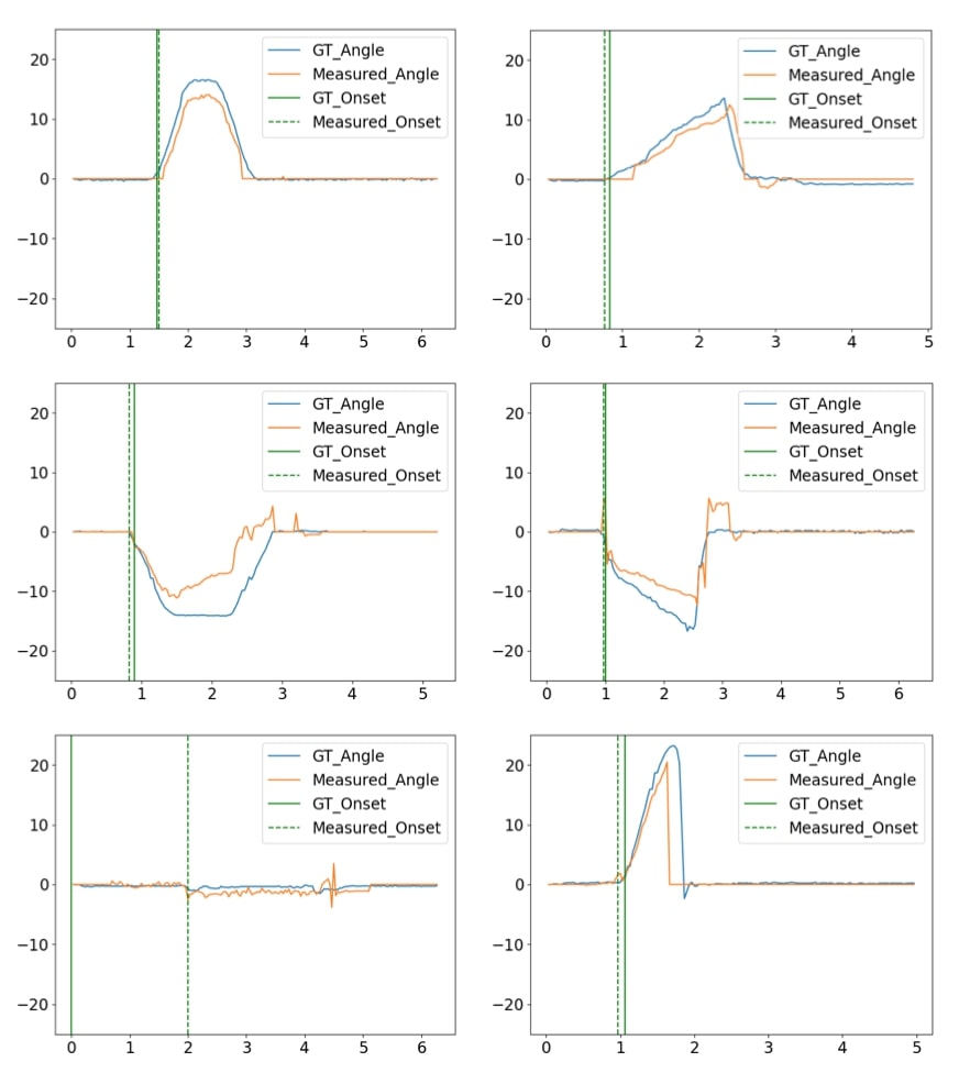
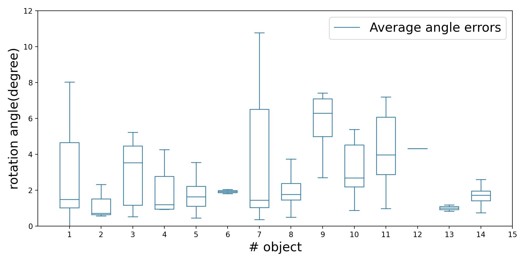
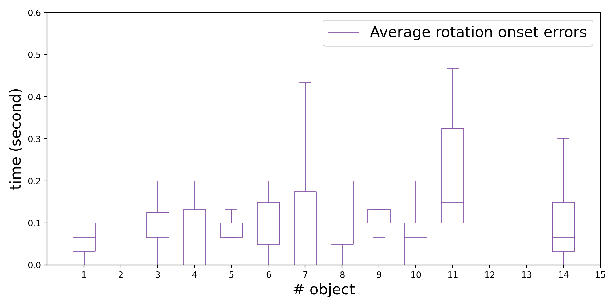
To numerically evaluate all rotation measurement results, we estimate the mean of the absolute error between the ground truth and the measured angle for each lifting frame in each grasp trial. The lifting frame starts from the rotation onset time stamp and ends when the object detaches from the tactile sensor. The overall average error in rotation angle measurement is 3.96∘. However, from our observation during experiments, for cases where the rotation angles are large, the angles measured are smaller than the ground truth values. This comes from the rotational slip occurring between the contact of the gel’s surface and the object. This can also be attributed to the adhesion between the gel and the object, which impedes the rotation. Unfortunately, due to the design of the sensor, these two scenarios are unavoidable. Therefore, we also evaluate the angle errors for the rotation angles under 10∘ to eliminate these effects. For rotation angles under 10∘, the average angle error is 2.69∘. The statistics of average angle error for all experiments can be seen in Fig. 10. When contour tracking is used in angle measurement, the average angle error is 3.33∘ for the general case and 2.33∘ for the case of rotation measurement under 10∘. As the numbers imply, both contour tracking and marker motion tracking give similar performance in measuring the rotation angle. Moreover, we evaluate the average time delay for rotation onset detection, as in Fig. 11. The overall error is 4.22 frames, which is around 0.14 seconds.
For classification between stable and rotational cases, in general, 134 cases out of 142 cases are classified correctly, where the success rate is 94.37%. Among them, 41 successful classifications out of 44 are stable cases with a success rate of 93.18%, and 93 successful classifications out of 98 are rotational cases with a success rate of 94.90%.
Most failures come from the imperfect grasping where the contact area is located at the margin of the image. As a result, the contact is only partially visible, and even disappears after lifting, making it hard to track either the markers or the contours.
IV-B Closed-Loop Regrasping Experiment
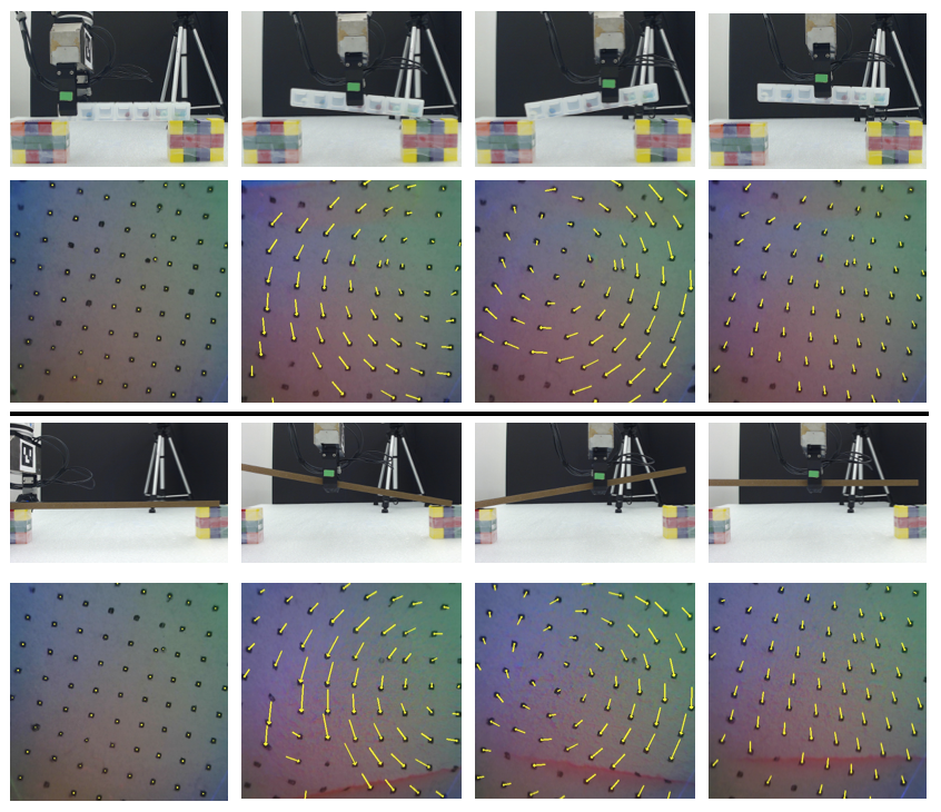
We follow the closed-loop regrasp framework using adaptive step size as proposed in III-F2. For each object, the robot starts near the geometric center of the object. The robot grasps the object at each grasp location and attempts to lift the object to a maximum height of 5 cm. Simultaneously, the rotation measurement algorithm analyzes each frame from the GelSight sensor. If it detects rotation greater than 5∘, it raises a preemptive signal to the robot through ROS. The robot then places the object back on the table. If no preemptive signal is sent till the maximum height of 5 cm, the robot then waits for 3s to check for rotation. If rotation is detected in either of the above two ways, the robot’s step size is updated according to the control framework proposed in III-F2. However, if rotation is not detected at this stage, the robot further lifts the object by 3 cm and holds it for 5s to indicate that a stable grasp pose has been achieved. The process is illustrated in Fig. 12. We manually label whether rotation occurred in a particular grasp. For a single object, we define a grasping loop as the object being grasped at multiple locations until it reaches the stable grasp pose. We conducted a total of 109 closed-loop regrasping experiments on 18 objects, at gripping speeds varying from 40-50 mm/s and maximum gripping force varying from 30-60 N. The rotation detection algorithm takes 0.045 s to process each frame while the manipulation happens.
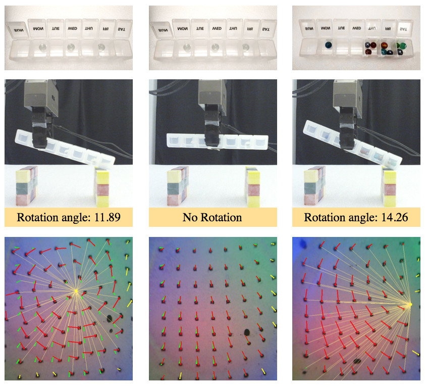
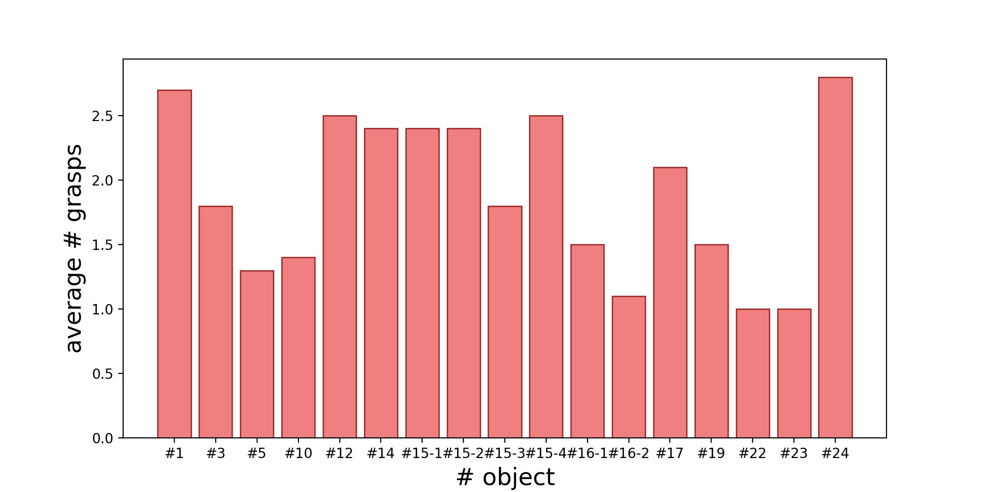
Results: In 105 out of the 109 experiments, the algorithm could drive the robot towards the object’s centroid and avoid rotations above a set threshold of 5∘, with a success rate of 96.3%. In 3 cases, the algorithm misclassified rotation as a stable grasp pose, and in 1 case a stable grasp pose as rotation. The primary reason for this failure is that the contacted area is small in the GelSight sensor’s FOV during the grasp resulting in very few contact markers being detected. In cases like a pills box with uneven distribution of marbles as shown in Fig. 12, our proposed method can drive the robot to a stable grasp pose in 2 regrasps on an average. Also, for objects like a spatula or vernier callipers(13, 22 in Fig. 7) with uneven mass distribution, our method can detect the centre of gravity in 1.5 regrasps on average. These objects are difficult to grasp stably using vision information alone due to their uneven mass distributions; however, our method proves to be efficient in detecting center of gravity for them. On average, the robot took one regrasp to reach the center of gravity for all the experimental objects. The average number of grasps for each object in the closed-loop experiments can be seen in Fig. 13. It took a maximum of 3 regrasps to reach the stable grasp pose across the set of objects.
V CONCLUSIONS
Rotational displacement during grasping is a common grasp failure, in which the robot grasps an object at a location far from its center of gravity. In this paper, we present an approach to detect rotational grasp failure from tactile sensing and a closed-loop regrasp system to stabilize the grasp. The method is based on measuring the rotation angle of the soft tactile sensor’s surface from tactile images, which directly correlates to the torque at the grasp surface. With the feedback of the rotation detection from tactile sensing, the robot attempts multiple regrasps and reaches a stable grasp location in the end to prevent huge rotation from happening.
In the future work, we plan to explore how learning based techniques can perform on the similar task of rotation measurement. In order for closed-loop regrasp control to work on objects of varied dimensions and shapes, we plan to include object detection and size estimation from external visual equipment and guide grasping. Also, we wish to explore control frameworks for multi-fingered robotic arms equipped with tactile sensors using our proposed method for measuring rotation. We believe higher camera fps and lower latency can help in scaling our proposed method to industrial applications.
References
- [1] A. Bicchi and V. Kumar, “Robotic grasping and contact: a review,” in Proceedings 2000 ICRA. Millennium Conference. IEEE International Conference on Robotics and Automation. Symposia Proceedings (Cat. No.00CH37065), vol. 1, 2000, pp. 348–353 vol.1.
- [2] K. Shimoga, “Robot grasp synthesis algorithms: A survey,” The International Journal of Robotics Research, vol. 15, no. 3, pp. 230–266, 1996.
- [3] J. Bohg, A. Morales, T. Asfour, and D. Kragic, “Data-driven grasp synthesis—a survey,” IEEE Transactions on Robotics, vol. 30, no. 2, pp. 289–309, 2014.
- [4] J. M. Romano, K. Hsiao, G. Niemeyer, S. Chitta, and K. J. Kuchenbecker, “Human-inspired robotic grasp control with tactile sensing,” IEEE Transactions on Robotics, vol. 27, no. 6, pp. 1067–1079, 2011.
- [5] W. Yuan, R. Li, M. A. Srinivasan, and E. H. Adelson, “Measurement of shear and slip with a gelsight tactile sensor,” in 2015 IEEE International Conference on Robotics and Automation (ICRA), 2015, pp. 304–311.
- [6] M. K. Johnson and E. H. Adelson, “Retrographic sensing for the measurement of surface texture and shape,” in 2009 IEEE Conference on Computer Vision and Pattern Recognition, 2009, pp. 1070–1077.
- [7] A. T. Miller, S. Knoop, H. I. Christensen, and P. K. Allen, “Automatic grasp planning using shape primitives,” in 2003 IEEE International Conference on Robotics and Automation (Cat. No.03CH37422), vol. 2, 2003, pp. 1824–1829 vol.2.
- [8] A. Collet, D. Berenson, S. S. Srinivasa, and D. Ferguson, “Object recognition and full pose registration from a single image for robotic manipulation,” in 2009 IEEE International Conference on Robotics and Automation, 2009, pp. 48–55.
- [9] R. Calandra, A. Owens, M. Upadhyaya, W. Yuan, J. Lin, E. H. Adelson, and S. Levine, “The feeling of success: Does touch sensing help predict grasp outcomes?” arXiv preprint arXiv:1710.05512, 2017.
- [10] A. Saxena, J. Driemeyer, J. Kearns, C. Osondu, and A. Y. Ng, Learning to Grasp Novel Objects Using Vision. Berlin, Heidelberg: Springer Berlin Heidelberg, 2008, pp. 33–42.
- [11] J. W. James, N. Pestell, and N. F. Lepora, “Slip detection with a biomimetic tactile sensor,” IEEE Robotics and Automation Letters, vol. 3, no. 4, pp. 3340–3346, 2018.
- [12] R. Calandra, A. Owens, D. Jayaraman, J. Lin, W. Yuan, J. Malik, E. H. Adelson, and S. Levine, “More than a feeling: Learning to grasp and regrasp using vision and touch,” IEEE Robotics and Automation Letters, vol. 3, no. 4, pp. 3300–3307, 2018.
- [13] D. Cockbum, J. Roberge, T. Le, A. Maslyczyk, and V. Duchaine, “Grasp stability assessment through unsupervised feature learning of tactile images,” in 2017 IEEE International Conference on Robotics and Automation (ICRA), 2017, pp. 2238–2244.
- [14] Y. Bekiroglu, R. Detry, and D. Kragic, “Learning tactile characterizations of object- and pose-specific grasps,” in 2011 IEEE/RSJ International Conference on Intelligent Robots and Systems, 2011, pp. 1554–1560.
- [15] J. Kwiatkowski, D. Cockburn, and V. Duchaine, “Grasp stability assessment through the fusion of proprioception and tactile signals using convolutional neural networks,” in 2017 IEEE/RSJ International Conference on Intelligent Robots and Systems (IROS), 2017, pp. 286–292.
- [16] J. Kwiatkowski, J. Lavertu, C. Gourrat, and V. Duchaine, “Determining object properties from tactile events during grasp failure,” in 2019 IEEE 15th International Conference on Automation Science and Engineering (CASE), 2019, pp. 1692–1698.
- [17] C. G. Atkeson, C. H. An, and J. M. Hollerbach, “Rigid body load identification for manipulators,” in 1985 24th IEEE Conference on Decision and Control, 1985, pp. 996–1002.
- [18] A. Murali, Y. Li, D. Gandhi, and A. Gupta, “Learning to grasp without seeing,” in Proceedings of the 2018 International Symposium on Experimental Robotics, J. Xiao, T. Kröger, and O. Khatib, Eds. Cham: Springer International Publishing, 2020, pp. 375–386.
- [19] R. Krug, A. J. Lilienthal, D. Kragic, and Y. Bekiroglu, “Analytic grasp success prediction with tactile feedback,” in 2016 IEEE International Conference on Robotics and Automation (ICRA), 2016, pp. 165–171.
- [20] F. R. Hogan, M. Bauza, O. Canal, E. Donlon, and A. Rodriguez, “Tactile regrasp: Grasp adjustments via simulated tactile transformations,” in 2018 IEEE/RSJ International Conference on Intelligent Robots and Systems (IROS), 2018, pp. 2963–2970.
- [21] Q. Feng, Z. Chen, J. Deng, C. Gao, J. Zhang, and A. Knoll, “Center-of-mass-based robust grasp planning for unknown objects using tactile-visual sensors,” in 2020 IEEE International Conference on Robotics and Automation (ICRA), 2020, pp. 610–617.
- [22] D. Kanoulas, J. Lee, D. G. Caldwell, and N. G. Tsagarakis, “Center-of-mass-based grasp pose adaptation using 3d range and force/torque sensing,” International Journal of Humanoid Robotics, vol. 15, no. 04, p. 1850013, 2018.
- [23] M. T. Francomano, D. Accoto, and E. Guglielmelli, “Artificial sense of slip—a review,” IEEE Sensors Journal, vol. 13, no. 7, pp. 2489–2498, 2013.
- [24] Q. Zhuo, L. Tian, P. Fang, G. Li, and X. Zhang, “A piezoelectret-based approach for touching and slipping detection in robotic hands,” in 2015 IEEE International Conference on Cyber Technology in Automation, Control, and Intelligent Systems (CYBER), 2015, pp. 918–921.
- [25] J. Reinecke, A. Dietrich, F. Schmidt, and M. Chalon, “Experimental comparison of slip detection strategies by tactile sensing with the biotac® on the dlr hand arm system,” in 2014 IEEE International Conference on Robotics and Automation (ICRA), 2014, pp. 2742–2748.
- [26] K. Van Wyk and J. Falco, “Calibration and analysis of tactile sensors as slip detectors,” in 2018 IEEE International Conference on Robotics and Automation (ICRA), 2018, pp. 2744–2751.
- [27] L. Li, F. Sun, B. Fang, Z. Huang, C. Yang, and M. Jing, “Learning to detect slip for stable grasping,” in 2017 IEEE International Conference on Robotics and Biomimetics (ROBIO), 2017, pp. 430–435.
- [28] Y. Yamada and M. R. Cutkosky, “Tactile sensor with 3-axis force and vibration sensing functions and its application to detect rotational slip,” in Proceedings of the 1994 IEEE International Conference on Robotics and Automation, 1994, pp. 3550–3557 vol.4.
- [29] C. Melchiorri, “Slip detection and control using tactile and force sensors,” IEEE/ASME Transactions on Mechatronics, vol. 5, no. 3, pp. 235–243, 2000.
- [30] Z. Su, K. Hausman, Y. Chebotar, A. Molchanov, G. E. Loeb, G. S. Sukhatme, and S. Schaal, “Force estimation and slip detection/classification for grip control using a biomimetic tactile sensor,” in 2015 IEEE-RAS 15th International Conference on Humanoid Robots (Humanoids), 2015, pp. 297–303.
- [31] M. Meier, F. Patzelt, R. Haschke, and H. J. Ritter, “Tactile convolutional networks for online slip and rotation detection,” in Artificial Neural Networks and Machine Learning – ICANN 2016, A. E. Villa, P. Masulli, and A. J. Pons Rivero, Eds. Cham: Springer International Publishing, 2016, pp. 12–19.
- [32] A. Bicchi, “Intrinsic contact sensing for soft fingers,” in Proceedings., IEEE International Conference on Robotics and Automation, 1990, pp. 968–973 vol.2.
- [33] S. Dong, W. Yuan, and E. Adelson, “Improved gelsight tactile sensor for measuring geometry and slip,” 2017 IEEE/RSJ International Conference on Intelligent Robots and Systems (IROS), pp. 137–144, 2017.