Scaling Theory of Three-Dimensional Magnetic Reconnection Spreading
Abstract
We develop a first-principles scaling theory of the spreading of three-dimensional (3D) magnetic reconnection of finite extent in the out of plane direction. This theory addresses systems with or without an out of plane (guide) magnetic field, and with or without Hall physics. The theory reproduces known spreading speeds and directions with and without guide fields, unifying previous knowledge in a single theory. New results include: (1) Reconnection spreads in a particular direction if an x-line is induced at the interface between reconnecting and non-reconnecting regions, which is controlled by the out of plane gradient of the electric field in the outflow direction. (2) The spreading mechanism for anti-parallel collisionless reconnection is convection, as is known, but for guide field reconnection it is magnetic field bending. We confirm the theory using 3D two-fluid and resistive-magnetohydrodynamics simulations. (3) The theory explains why anti-parallel reconnection in resistive-magnetohydrodynamics does not spread. (4) The simulation domain aspect ratio, associated with the free magnetic energy, influences whether reconnection spreads or convects with a fixed x-line length. (5) We perform a simulation initiating anti-parallel collisionless reconnection with a pressure pulse instead of a magnetic perturbation, finding spreading is unchanged rather than spreading at the magnetosonic speed as previously suggested. The results provide a theoretical framework for understanding spreading beyond systems studied here, and are important for applications including two-ribbon solar flares and reconnection in Earth’s magnetosphere.
I Introduction
Magnetic reconnection is a fundamental process that converts magnetic energy into kinetic and thermal plasma energy through a change in magnetic topology [1, 2]. It mediates eruptive solar flares [3] and geomagnetic substorms [4] and is thought to be an important process in numerous settings in high-energy astrophysics [e.g., [5, 6] and references therein]. Early models treated reconnection as two-dimensional (2D) [7, 8, 9], but naturally-occurring reconnection is a 3D process [e.g., [10, 11]].
One way the 3D nature of reconnection is manifested is that the x-line where the magnetic field topology changes has a finite extent in the direction normal to the plane of reconnection. [Note, we use the term "x-line" to refer simply to the line along which reconnection takes place, regardless of whether it is a separator, quasi-separator or a squashed 3D null point [12]. We do not use the term to mean a line of x-points, which can arise in 2D systems but is topologically unstable in 3D.] Spatially confined reconnection regions for which the extent of the region undergoing reconnection does not change in time have been studied theoretically and numerically (Refs. [13, 14, 15, 16, 17, 18, 19] and Pyakurel et al., submitted). Alternately, the region undergoing reconnection can elongate, which we synonymously call spreading, over time. Such behavior has been observed in the solar corona during two-ribbon solar flares [20, 21, 22, 23, 24, 25, 26, 27, 28] and prominence eruptions [29], at Earth’s magnetopause [30, 31, 32], in Earth’s magnetotail [4, 33, 34, 35], and in laboratory reconnection experiments [36, 37, 38, 39], and is thought to occur in the production of extremely extended reconnection events in the solar wind [40, 41, 17]. Studying how reconnection spreads, which is the focus of the present study, is important in many settings because it impacts secondary processes such as particle acceleration and the global efficiency of the release of large-scale magnetic energy.
There have been many numerical studies of 3D reconnection spreading in various settings. During anti-parallel quasi-2D reconnection, the consensus is that spreading occurs in the direction perpendicular to the reconnection plane at the speed and direction of the current carriers [42, 43, 13, 44, 45, 46, 47, 15, 48]. If one species carries all the current, the spreading is unidirectional; if both species carry some current the spreading is bidirectional.
A number of physical mechanisms for spreading have been suggested. It was argued [42] that spreading of collisionless reconnection is caused by electrons convecting the reconnected magnetic into the region not undergoing reconnection [see also [49, 13]]. They argued it was caused by a shock-like “reconnection wave” and motivated the result using linear theory. The electron magnetohydrodynamic (eMHD) induction equation is
| (1) |
where is the magnetic field, is the number density, is the proton charge, is the current density, and is the speed of light. Linearizing around the out of plane current profile, the perturbed reconnected (normal) magnetic field is governed by
| (2) |
This shows that the magnetic field of the x-line is convected at a velocity associated with the current carriers, assumed to be electrons in their work. When ions carry some of the current, spreading occurs at the speed of the current carriers in their respective directions [13, 45, 47]. If the thickness of the current sheet is , then in the reference frame in which the electrons carry all the current, the spreading speed scales as
| (3) |
where is the upstream reconnecting magnetic field strength, is the ion inertial scale, is the Alfvén speed based on , and is the ion mass. The functional dependence on was confirmed in simulations [13], and it was similarly shown that the relevant speed of the current carriers is that of the initial current sheet thickness rather than the kinetic-scale thickness after reconnection has started [45, 50]. Interestingly, if electrons carry all the current for anti-parallel reconnection, it was shown that reconnection does not spread in the resistive-MHD model [47]. Moreover, reconnection can merely convect without the region undergoing reconnection elongating in the out of plane direction [13].
An alternate mechanism for collisionless anti-parallel reconnection spreading was presented, based on pressure instead of magnetic field [43, 47]. The region where reconnection occurs was found to be of lower plasma pressure than the non-reconnecting regions. The low pressure convects with the current carriers into the non-reconnecting regions, inducing inwards flow which causes reconnection sequentially in the out of plane direction. A related model was developed to explain observations of impulsive reconnection in the Magnetic Reconnection eXperiment (MRX) [38, 39]. In their experiment, the initial conditions had an electron flow gradient in the out of plane direction. This gradient requires an inflow in an adjacent non-reconnecting region to preserve mass continuity, producing a sequential onset of reconnection.
Spreading of magnetic reconnection is qualitatively different when there is a background out of plane (guide) magnetic field, which commonly is present in reconnection in solar flares [28], the solar wind [51], and the dayside magnetopause [31]. Laboratory experiments showed that, for a strong guide field, the spreading is bidirectional with a speed given by the Alfvén speed based on the guide field strength rather than the speed of the current carriers [36]:
| (4) |
Two-fluid simulations found the same scaling with the out-of-plane (guide) magnetic field [46, 52]. The spreading has been described as being mediated by Alfvén waves [46], whistler waves and flow induced waves [52], and kinetic Alfvén waves [50]. Recently, it was shown in simulations of guide field reconnection with asymmetric plasma conditions that spreading in current sheets thinner than ion scales is bidirectional at the Alfvén speed, but is at the current carrier speed for thicker current sheets [50]. The different behavior for different current sheet thicknesses was attributed to the reduced tearing instability growth rate for wider current sheets. A guide field can also impede the spreading of reconnection due to the presence of multiple oblique x-lines [53].
This study presents a number of new results on the fundamental physics of the spreading of reconnection of finite extent. We generalize the theory of anti-parallel reconnection spreading [42], showing that it can be interpreted in the form of a scaling analysis and showing that the same theory can be used to derive from first principles the scaling of the spreading speed in the strong guide field limit, thereby uniting the understanding of reconnection spreading under a single first principles approach. New results include: (1) We argue that the key physical aspect of x-line spreading is the induction of an x-line topology in the non-reconnecting region [see also Jain et al. (2013)[48]], which is carried out by the gradient in the electric field in the outflow direction at the interface between the reconnecting and non-reconnecting regions. If an x-line topology is not induced in a given direction, reconnection does not spread in that direction. (2) The physical cause of reconnection spreading without and with a guide field are different, with convection at the Hall scale and MHD-scale magnetic field bending, respectively, playing key roles. We validate the theoretical results using 3D two-fluid and resistive-MHD numerical simulations, for both anti-parallel and guide field reconnection. (3) The theory explains why anti-parallel reconnection in the resistive-MHD model does not spread [47]. (4) We find that a determining factor for whether a current sheet spreads or convects with a fixed length in a numerical simulation is the aspect ratio of the domain, which we suggest is controlled by the amount of free magnetic energy in the system. (5) Finally, we perform a test of whether the results obtained herein are dependent on the manner in which reconnection is excited in the system. This is important because it has been suggested [54] that reconnection spreads at the fast magnetosonic speed rather than the speed of the current carriers. Physically, this mechanism could occur if reconnection is initiated through a pressure pulse squeezing the current sheet. As simulations typically initiate reconnection using a magnetic perturbation, it is important to assess whether the speed of the spreading depends on the way in which reconnection is seeded. Using a pressure pulse to initiate reconnection, we find that anti-parallel reconnection spreads at the current carrier speed rather than the magnetosonic speed.
The layout of this paper is as follows. In Sec. II, we discuss the theory of 3D reconnection spreading and derive a number of key implications about the physical cause of reconnection spreading and applications to collisionless and collisional systems with and without a guide field. In Sec. III, we discuss our numerical simulation setup. In Sec. IV, we discuss the results of our simulations. We offer conclusions and discuss new insights as a result of this work in Sec. V.
II Theory of reconnection spreading
II.1 General considerations
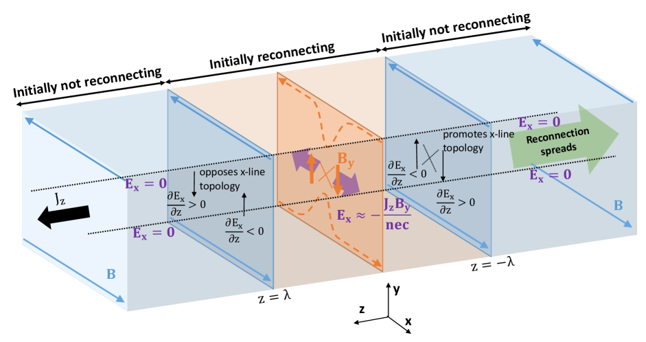
We use a coordinate system in which is the direction of the initial current, the current sheet is centered around , and is the direction of the equilibrium reconnecting magnetic field, with for and for . We use a reference frame where the electrons fully carry the out of plane current. The asymptotic reconnecting magnetic field strength is , there may be a guide field of strength , and the current sheet has an initial thickness . The system is sketched schematically in Fig. 1 for the case without a guide field. The plane is shown with two dotted lines. At a given time, reconnection is occurring in a localized part of the current sheet with finite out of plane extent , shown with orange shading in the figure, while the parts of the system shaded blue are not undergoing reconnection.
As in the model reviewed in the Introduction, we consider the time evolution of the reconnected magnetic field . To generalize the previous approach [42], we begin from Faraday’s law, , where is the electric field. At the interface between reconnecting and non-reconnecting regions, gradients in the direction exceed gradients in the direction, so the term that dominates production is [see also [48]]
| (5) |
A scaling analysis allows us to find a characteristic out of plane spreading speed , given by
| (6) |
where the spatial finite difference is evaluated at the boundary between the reconnecting and non-reconnecting regions, and we associate with the speed of the spreading . We retain the minus sign, as it gives information about the direction of propagation.
We first make contact with previous work. For anti-parallel collisionless reconnection, it was argued that reconnection spreading occurs via out of plane convection by the electrons. The electric field associated with this is , from the Hall term. Using this in Eq. (6) and taking at the interface between reconnecting and non-reconnecting regions gives
| (7) |
This reproduces the result that reconnection spreads at the speed and direction of the current carriers in Eq. (2). In our approach, the result follows from a scaling analysis rather than linear theory.
In what follows, we argue that Eq. (6) is useful for predicting the spreading speed beyond only anti-parallel reconnection. More generally, the component of the net electric field in the outflow direction is given by the generalized Ohm’s law
| (8) |
where is the (ion) bulk flow velocity, is the (scalar) electron pressure, is the electron mass, and is the resistivity. The right hand side includes the convection term, Hall term, electron pressure gradient term, electron inertia term, and resistive term in order of appearance. We show that in different settings, different terms can dominate. We find the electron pressure gradient and electron inertia terms do not impact spreading in current sheets at or above ion inertial scale thicknesses.
Before considering specific systems, we elucidate what our approach reveals about the physical mechanism for reconnection spreading. Previous work [42] suggested the evolution of is what determines spreading. Physically, in order to seed an x-line in a plane in which there is initially no x-line, one needs to generate a normal magnetic field with a bipolar structure of the proper polarity [see also [48]]. If the coordinate of the x-line is , then an x-line is seeded if for and for for the assumed directionality. From Eq. (5), the signs of the gradient of the electric field at the ends of the region undergoing reconnection determine whether is locally positive or negative for and , which determines whether an x-line develops over time in the non-reconnecting region. We argue the sign of the gradient of the electric field in the outflow direction is a more fundamental interpretation of how reconnection spreads via convection.
We note a subtlety that is important for numerical studies of reconnection spreading and may be important in naturally occurring reconnection. Many theoretical developments of reconnection spreading, including the treatment in this section, are based on the propagation of a small into regions not previously undergoing reconnection. However, the presence of is not synonymous with the onset of reconnection. Rather, the presence of triggers the tearing instability which makes grow in time, and it is only after getting to large amplitudes that steady reconnection is set up. Thus, there is a time delay between when spreads into a region not undergoing reconnection and when reconnection begins in earnest. This has been seen in previous simulation studies [42], and more recently has been noted as an important factor in the spreading of reconnection in thick current sheets for which the time scale of the tearing instability is longer [50]. For the present study, the time delay between the appearance of and the onset of full-fledged reconnection is the same at all locations, so the spreading speed of reconnection is unchanged by the delay. Consequently, in this study, it is sufficient to study the spreading speed of the normal magnetic field as a proxy for the spreading speed of the onset of full-fledged magnetic reconnection.
II.2 Spreading of collisionless anti-parallel reconnection
We exploit the results of the previous subsection to develop new insight on the physics of spreading for anti-parallel collisionless (Hall) reconnection. In Fig. 1, the dark blue arrows represent magnetic field lines within the blue shaded regions in which reconnection is not taking place, which are straight because there is no reconnection to bend them towards the plane. In contrast, the dashed orange arrows depict the projection of a representative reconnecting magnetic field line in the plane within the orange shaded region where reconnection is occurring, which bend in towards the x-line. As previously noted [42, 13], the out of plane current is carried in the direction by electrons convecting in the direction. Thus, the x-line topology governed by , depicted by the thick vertical orange arrows in the region undergoing reconnection, is convected in the direction and reconnection spreads in that direction (the green arrow) in this reference frame.
We reinterpret this in terms of the electric field and the induced magnetic field in the non-reconnecting regions. In the region where reconnection is taking place, the out of plane current (the thick black arrow) in the presence of the reconnected magnetic field (the thick orange arrows, negative for , positive for ) produces a non-zero component of the Hall electric field in the outflow direction , pointing away from the x-line as denoted by the purple arrows. This is relatively uniform between and , but at the boundaries of the reconnecting region at , there is a non-zero out of plane gradient . From Faraday’s law, this produces a in the adjacent non-reconnecting planes, positive for and and negative for and , represented by the four thin black arrows in the planes. For the non-reconnecting plane adjacent to the boundary, there is initially no , so the presence of a generates a magnetic field that seeds an x-line topology (shown as an X with black dotted lines), thus promoting the spreading of the x-line in the direction of electron convection, as expected. In contrast, in the non-reconnecting plane adjacent to , has the opposite polarity, which serves to weaken the existing , and thus the x-line and therefore reconnection do not spread in the direction. This provides an alternate, but equivalent, understanding of why reconnection does not spread in the direction of the current in the reference frame in which the electrons carry the current.
II.3 Lack of spreading of anti-parallel reconnection in resistive-MHD
In collisional reconnection described by resistive-MHD, the Hall, electron pressure, and electron inertia terms are dropped from the generalized Ohm’s law [Eq. (8)]. Then, the only terms that can produce an are , and . For anti-parallel collisional reconnection in the reference frame in which the electrons carry the out of plane current, and are both zero. Thus, there is no spreading in collisional reconnection due to convection in the reference frame in which the electrons carry the out of plane current. This result is consistent with previous resistive MHD simulations [47], and provides a first-principles reason for the absence of spreading in this case. We point out that the resistive term, with , can in principle cause spreading. This spreading is bidirectional, as magnetic diffusion of at the boundary between the reconnecting and non-reconnecting region induces an x-line topology in the non-reconnection part. Using , where is the length scale of the transition between the reconnecting and non-reconnecting regions, Eq. (6) gives
| (9) |
i.e., the diffusion velocity across the boundary. This mechanism may be relevant for spreading in collisional plasmas, such as the chromosphere or some laboratory experiments. However, for most settings of heliophysical interest, the resistivity is exceedingly small, so the spreading due to resistivity is small on dynamical time scales.
II.4 Spreading of guide field reconnection
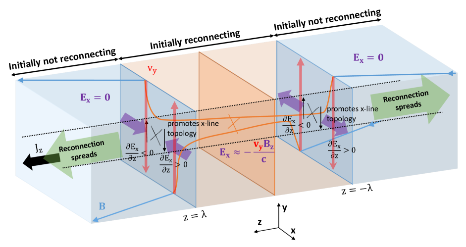
The physical cause of reconnection spreading with a non-zero guide field is fundamentally different than with no guide field. For simplicity, we consider the limit where the guide field is much larger than the reconnecting magnetic field, , and that the current sheet is not sufficiently thicker than the ion gyroscale, at which point the mechanism for reconnection spreading can change because of the guide field dependence of guide field reconnection on the growth rate of the collisionless tearing instability [50]. Figure 2 shows a sketch of reconnection spreading in the large guide field limit. As in Fig. 1, blue regions are not initially undergoing reconnection. The magnetic field in this region is shown with dark blue lines, depicted with a strong component. The region initially undergoing reconnection with length is shown in orange. As reconnection occurs, the upstream magnetic field in this region convects inward towards the neutral line, shown in dark orange lines. This bends the upstream magnetic field, introducing a kink in the magnetic field localized near the interface of the reconnecting and non-reconnecting regions. This kinked magnetic field provides a curvature force, which drives a bulk flow in the vertical () direction, depicted as red arrows near the planes. The flow, therefore, has a quadrupolar structure in the plane. The normal flow in a region with a guide field produces a convective electric field , depicted by the purple arrows. It is strongest in a thin region near the interface, and also has a quadrupolar structure in the plane. Since has a gradient in the direction, Faraday’s law implies that is generated in that region, with the sign of being given by Eq. (5). The induced fields are depicted by the thin black arrows at . At both edges, the magnetic topology generated by the induced is of an x-line, so the x-line spreads in both out-of-plane directions. This is consistent with the known result that guide field reconnection spreads bidirectionally. We stress that this sketch of the physics is valid for both collisionless and collisional reconnection. Essentially, this bending of the magnetic field line is physically similar to a rotational discontinuity or launching an Alfvén wave. For collisionless reconnection in current sheets at gyroscales, this field line bending becomes a kinetic Alfvén wave, as was previously elucidated [50].
We now perform a scaling analysis to obtain the spreading speed in the strong guide field limit. The bulk flow in the direction due to the curvature force from the bent upstream magnetic field is described by the momentum equation
| (10) |
In writing this, we use that the large guide field limit implies in the convection electric field in Ohm’s law, as both the out of plane bulk flow and the reconnected field are small during the early stages of reconnection.
A scaling analysis on this equation gives
| (11) |
where we have taken between adjacent reconnecting and non-reconnecting planes and as per equation (6). Then, the relevant term in Eq. (8) gives as
| (12) |
and using this result in Eq. (6) reveals
| (13) |
This reproduces the known result that reconnection with a large guide field spreads bidirectionally at the Alfvén speed based on the guide field in Eq. (4).
III Simulation Setup
Simulations are carried out using the two-fluid code F3D [55], which updates the continuity, momentum, induction, and pressure equations, and can include the Hall, resistive, and electron inertia terms in the generalized Ohm’s law. Time is stepped forward using the trapezoidal leapfrog algorithm [56] and spatial derivatives are fourth order finite differences. For simulations with the Hall term, lengths are normalized to the ion inertial scale , time is normalized to the inverse ion cyclotron frequency , velocities to the Alfvén speed , electric fields to , and temperatures to , where is the initial upstream reversing magnetic field magnitude, is the initial upstream density, and is Boltzmann’s constant. When the Hall term is absent, the only differences to the normalizations are that lengths are normalized to an arbitrary length , times are normalized to , and resistivity is normalized to .
The computational domain has dimensions , where and correspond to the outflow and inflow directions in 2D, respectively, and is perpendicular to the 2D reconnecting plane. Boundary conditions are triply periodic, and the system size is chosen to be large enough that the boundaries do not impact the relevant dynamics. The grid scale is . The lower resolution in the out-of-plane direction has been used before [13, 46], and is justified since out-of-plane dynamics in our setup change more slowly than dynamics in the reconnection plane. When electron inertia is included, the ion-to-electron mass ratio is , and we expect the relevant results are independent of this value, since previous work on the spreading of anti-parallel reconnection has shown that the dynamics of x-line spreading are insensitive to the mass ratio [13] and the terms in Ohm’s law that contribute to reconnection spreading in the theory (the Hall and convection electric fields) are independent of the mass ratio.
The initial conditions consist of two oppositely directed current sheets. The -component of the initial magnetic field is given by , where is the initial current sheet thickness. When a guide field is included, it is uniform. The initial density is uniform with a value of 1, and a non-uniform temperature varying from 1 to 1.5 is used to balance magnetic pressure in the current sheet. The plasma pressure is provided fully by ions and is treated as adiabatic, while the electrons are assumed cold at all times. The electrons carry all of the initial current.
The resistivity is identically zero for simulations employing the Hall term, and is 0.004 for the resistive-MHD simulations. Fourth-order diffusion is included in all equations with coefficients and a larger diffusion coefficient in the direction because the grid scale is larger. The time step is for all simulations with no guide field. For simulations with a guide field, a smaller time step of and a larger fourth-order diffusion coefficient are used to account for the faster dynamics in the out of plane direction. The diffusion coefficient and time step values are varied in trial simulations to ensure they do not play any significant role in the numerics.
We employ simulations with initial thickness . We repeat the simulation of anti-parallel reconnection with different uniform current sheet thicknesses and and the guide field simulation with to confirm that in all cases, the local physics remain qualitatively similar to their counterparts and that the spreading speeds are consistent with previous work [13]. When a guide field is included, we use , which is sufficient to be in the large guide field limit.
Unless otherwise stated, we initialize the simulations with a coherent perturbation in the magnetic field. To do so, the component of the perturbed vector potential is defined as
| (14) |
for and 0 for , where is a constant and the envelope has the form
| (15) |
where defines the initial half-extent of the coherent perturbation in the out of plane direction. We use unless stated otherwise. The resulting magnetic perturbation seeds an x-line/o-line pair in the plane for only the upper current sheet at , localized to . We perturb only the upper current sheet because doing so prolongs the timescale for the interaction between the two current sheets due to flows in the -direction and thus ensures the reconnection occurring in the upper sheet at later times is purely due to reconnection spreading in the upper sheet. To ensure the spreading has no dependence on , we perform a suite of simulations with an anti-parallel field configuration with with varying of and , with all other parameters held the same. We find that affects the initial extent of the reconnection region in the direction at the time of onset, which is to be expected, but the spreading of reconnection is unaffected. Incoherent noise in the and components of the magnetic field at the level is also used to break symmetry, which prevents secondary magnetic islands from staying in the initial x-line location [55].
IV Results
IV.1 Anti-parallel collisionless reconnection spreading
We begin by testing the theory in Sec. II.2. To do so, we need to verify the structure and the dominant contributor of the electric field and the time evolution of the magnetic field near the boundary of the initial reconnecting region.
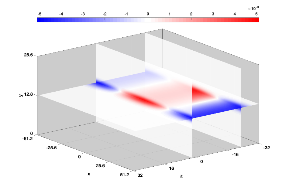
We investigate the electric and magnetic field structure at , when the perturbed is spreading out from its initial location, but before full-fledged reconnection is going at its steady rate (which occurs closer to ), as discussed in Section II.1. Figure 3 shows the net electric field component . Planar cuts through the upper (perturbed) current sheet and through the reconnecting planes at and near the boundaries of where reconnection occurs are shown. These planes are selected because the x-line seeded by the perturbation is initially between , but this region drifts in the direction, the direction of electron convection. The initial convection of the perturbed region before reconnection spreads is consistent with the behavior observed in Fig. 1 of Huba and Rudakov (2002)[42], though it was not discussed in their study.
The red-white-blue color map for the electric field ranges from to . The two zeroes of in the reconnecting region (in white) at and coincide with the x-line and o-line, respectively. The electric field is qualitatively similar at later times when the x-line is significantly longer in extent in the direction. The bipolar structure of points outwards from the x-line, consistent with the sketch in Fig. 1. The largest contributor to is the Hall term , as expected [42]. It has a maximum magnitude of 0.005 and is two orders of magnitude larger than the next largest contribution from the convection term .
| Anti-Parallel | ||||
|---|---|---|---|---|
| -0.00045 | 0.00045 | 0.00048 | -0.00048 | |
| -0.00056 | 0.00058 | 0.00056 | -0.00056 |
| Guide Field 3 | ||||
|---|---|---|---|---|
| 0.00050 | 0.00026 | -0.00053 | -0.00027 | |
| 0.00041 | 0.00035 | -0.00043 | -0.00038 |
To quantitatively confirm that the induction of is caused by , we compute the out of plane gradient at both boundaries of the reconnecting region to the left and right of the initial x-line, and , respectively. We use least squares to fit a line to as a function of through the center line of the upper current sheet from and to approximate . We calculate the local time derivative at the midpoint of the specified ranges in , determined with a time-centered difference between and . The results are gathered in Table 1. The similarity between the two terms shows that the main contribution to comes from , as expected.
The signs of in the plane are negative at and positive at , to the left and right of the zero of , respectively. This serves to promote an x-line topology in the plane. In contrast, at , the signs of oppose the formation of an x-line, consistent with our explanation of why reconnection does not spread in the direction. These results confirm our theoretical predictions for anti-parallel collisionless reconnection spreading.
IV.2 Guide field collisionless reconnection spreading
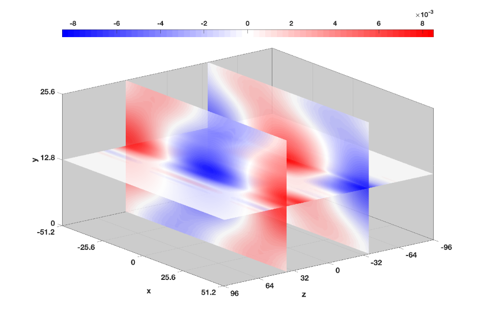
We now discuss the large guide field case. Figure 4 shows the net electric field component at for a simulation with guide field , again when the perturbed is spreading out from its initial location, but before full-fledged reconnection is going at its steady rate. Planar cuts are shown at through the upper (perturbed) current sheet and the and planes near the boundaries between the reconnecting and non-reconnecting regions. The two zeroes of at the intersections of the planes (in white) are again located at approximately and , coinciding with the x-line and o-line, respectively. Note, has a much larger extent in the direction than for the anti-parallel case, which is localized within an ion inertial scale. That extends far beyond the current sheet to MHD scales is typical of reconnection with a large guide field. When reconnection is occurring, ion inflows extend into the upstream region, well outside the current layer to MHD scales. In the absence of a guide field , the associated convection electric field in the upstream region is negligible. This is because the only contribution to is the quadrupolar Hall magnetic field, which is very small at MHD scales upstream of the diffusion region. This explains why is localized to the current layer in the case without a guide field (see Fig. 3). However, if there is a large guide field , the electric field is non-zero, both at Hall scales and beyond the current layer into MHD scales because of the ion inflow, as is seen in Fig. 4
The largest contributor to the electric field during the initial spreading phase is the convection term , which has a maximum magnitude of 0.009 and is three times larger than than the next largest contribution from . The quadrupolar structure of points inwards towards the x-line at and outwards from the x-line at , consistent with the sketch in Fig. 2.
We note that there is a small amplitude oscillatory signature at the leading edges of the signal. This is reminiscent of low amplitude oscillatory behavior observed in Jain and Buchner’s (2017) study[52] in the outermost edges of the reconnecting region, although in our simulation we do not see the larger amplitude oscillations they observed in between. Understanding these differences is outside of the scope of the present study. Regardless, due to the smallness of this oscillatory signal in our study ( compared to for the non-oscillatory signal), it is not playing any significant role in the spreading. To quantitatively confirm the induction of is caused by the convective electric field, we compute at both boundaries of the reconnecting region to the left and right of the initial x-line, and respectively, using a similar approach as the previous subsection, at and . We then compare to at the midpoint of the specified ranges and , computed as in the previous subsection. The results are gathered in Table 2. The similarity between the two quantities shows that the main contribution to comes from , as we predict in our scaling of Eq. (12) for the large guide field limit. The signs of show that develops with a negative sign at and a positive sign at , to the left and right of the zero of , respectively, at both and . This implies the magnetic topology is that of an x-line at both and planes, consistent with the model for why the x-line spreads in both the and directions.
Additionally, we test the prediction that the bulk flow is driven by the curvature force due to the bent upstream magnetic field at the boundaries of the reconnecting region by directly computing the left and right hand sides of Eq. (10) with simulation data. For the right hand side, we first compute at near the ends of the reconnecting region through , using a least squares fit of as a function of from both and and to the left and right of the x-line at and , respectively. Then, the numerical estimate for the curvature force term is (in code units). The left hand side is then computed locally at the midpoints and with a time-centered difference between and . The results are gathered in Table 3. The similarity of the two terms is strong evidence that the curvature force drives the bulk flows near the boundaries of the reconnection region in guide field reconnection. In summary, our simulation results confirm the predictions about the electric and magnetic fields in guide field reconnection in Section II.4.
| Momentum Eqn. | ||||
|---|---|---|---|---|
| -0.00021 | 0.00024 | 0.00026 | -0.00043 | |
| -0.00021 | 0.00014 | 0.00023 | -0.00045 |
IV.3 Spreading of collisional reconnection in resistive-MHD
Here, we study the spreading of collisional reconnection in resistive-MHD to test the predictions in Sec. II.3. For these simulations, the initial out-of-plane length scale in of the transition is from Eq. (15) and , so Eq. (9) gives a predicted spreading speed of (in code units). For the duration of the simulations carried out here, the distance reconnection would spread from resistive effects is expected to be negligible. Consequently, we expect no spreading for anti-parallel reconnection, but spreading will occur for guide field reconnection.
We carry out two 3D simulations using the resistive-MHD model. One has no guide field, and one has guide field . The initial current sheet thickness is . All other system properties and initialization parameters are the same as described in Sec. III. For the anti-parallel reconnection simulation, we find that reconnection does not spread up to the simulated time (not shown). If spreading were to occur at the speed of the current carriers , we would expect reconnection would spread a distance in the simulated time. This would be clearly observable, as this is longer than the computational domain in the direction. The region undergoing reconnection also does not convect in the out of plane direction, as the electrons initially carry all the current. These findings are consistent with previous results [47]. The region undergoing reconnection also does not convect in the out of plane direction, as the electrons initially carry all the current. With , reconnection spreads bidirectionally (not shown), as in the collisionless two-fluid simulation. This confirms that, for the parameters of our study, there is no spreading for anti-parallel reconnection in which electrons carry the current within the resistive-MHD model, that MHD physics drives the spreading when there is a guide field, and that collisions play no important role in reconnection spreading.
IV.4 Dependence of spreading on system aspect ratio
An interesting result arises from comparing our anti-parallel collisionless reconnection simulation with (used to confirm the results from the simulation do not depend on the current sheet thickness) with previous knowledge. In particular, we find that reconnection spreads with , while a previous study found that reconnection with a current sheet of that thickness developed a reconnecting region of finite extent in the direction and simply convected at the speed of the current carriers rather than spread [13]; see the dashed lines of their Fig. 3a. Similar behavior was observed in other studies of Hall reconnection spreading in relatively thick current sheets [15].
The difference between the present and previous simulations is that the prior studies used a square computational domain in the plane, whereas our domain is twice as big in the direction than in the direction. We repeat our simulation with a current sheet of thickness in a square computational domain with , as in Shay et al. (2003)[13]. We also find the x-line remains a fixed length and convects rather than spreads.
We demonstrate our result graphically using a plot of the reconnected magnetic field . For a given plane we find the reconnection region by first finding the zeroes of through the symmetry line of the current sheet in the plane and determine if the magnetic topology is that of an x-line or an o-line. For a current in the direction, changing from positive to negative with increasing is an x-line and from negative to positive is an o-line. If there are multiple x-lines, we define the primary one as that with the largest out-of-plane current . The strength of the reconnected field increases from zero away from the reconnection region until the downstream edge of the electron diffusion region. At every plane of constant and at every time , we use the average magnitude of at the left and right downstream edges of the electron diffusion region as a proxy for the appearance of reconnection and denote this quantity as .
For the distance from the x-line to the downstream edges of the electron diffusion region, we note that the collisionless reconnection rate is typically [e.g., [57, 58, 59]], which is also comparable to the aspect ratio of the diffusion region , where is its thickness (in the direction) and is its length (in the direction). The thickness of the electron diffusion region [2] is the electron inertial scale , so one expects the length of the electron diffusion region to be approximately . For this study, since . We validate this choice by visual inspection of cuts of , confirming this choice of reasonably represents where the strength of the reconnected magnetic field is near its first maximum. Consequently, we compute the average reconnected field magnitude at the downstream edges of the electron diffusion region for each plane as
| (16) |
where is the location of the x-line in the plane in question.
This plot shows reconnection spreads, in contrast to the results in a square computational domain in which the x-line convects without spreading [Fig. 3a of Shay et al. (2003)[13]].
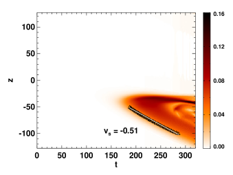
The average reconnected field for the upper current sheet is shown as a stack plot of time and out-of-plane coordinate for the rectangular computational domain in Fig. 5. The time delay between the spreading of and the onset of full-fledged reconnection is apparent as the white space on the left side of the plot; the reconnection does not begin at until even though the perturbed would have reached that location by . The triangular shape of is representative of reconnection that is spreading, and not convecting with a fixed extent. A reconnecting x-line that is merely convecting without spreading would appear as a diagonal stripe, with a fixed extent in the -direction. An example of this is in Fig. 3(a) of Shay et al. (2013)[13]; the dashed lines there show a reconnecting x-line that convects with a fixed length. The interior structures within the overall triangular region are due to magnetic islands that arise after reconnection at that location has reached its steady state. To calculate the spreading speed, we define onset at a given plane to be when exceeds 0.04. Onset times for individual planes are plotted in Fig. 5 as black triangles for a chosen interval in . The spreading speeds are simply the slope of the collection of points denoting the onset time. We determine this slope using a least squares fit. We find the spreading speed is , consistent with Eq. (3), as expected. Moreover, in a separate simulation with with the same square domain, we find that fast reconnection does not occur in the simulated time, whereas reconnection does occur in the rectangular cross section domain and spreads at the current carrier speed rather than merely convecting.
These results suggest that the aspect ratio of the reconnecting plane of the computational domain contributes to whether reconnection spreads or convects. We hypothesize that reconnection in the square domain stops because the reconnection runs out of free magnetic energy relatively quickly, while in the rectangular domain there is more free energy and thus the reconnection persists longer, consistent with the stack plot. This is only a single simulation, though, so future work is needed to test this hypothesis.
IV.5 Dependence on perturbation structure
To test whether the results obtained here are dependent on the manner in which reconnection is initiated in the system, we carry out an anti-parallel reconnection simulation with current sheet thickness , with the Hall effect and electron inertia turned on. Instead of perturbing the current sheet with a coherent perturbation of the magnetic field [see Eq. (14)], we perturb the system with localized regions of higher plasma pressure localized just upstream of the current sheet. This perturbation is designed to drive flow towards the current sheet in a localized region to seed an x-line. The pressure perturbation we employ has the form
| (17) | |||
where is the amplitude of the upstream pressure perturbation, is the desired coordinate of the x-line, is the extent of the pressure perturbation in the direction, is the location of the center of the current sheet being perturbed, is the thickness of the pressure perturbation in the direction, is the distance upstream of the current layer on each side that the pressure perturbation is centered, and is the same envelope in Eq. (15) enforcing localization in between .
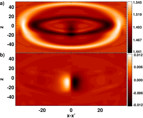
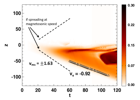
The pressure perturbation launches a pulse that propagates out in all directions. The ion pressure in a cut through at is shown in Fig. 6(a). The leading edge of the pressure pulse at this time is at , so its velocity is approximately 35 / 20 . This compares favorably to the fast magnetosonic speed, , as expected. The pressure pulse drives flow toward the current sheet which initiates reconnection, as desired, and the reconnection does spread in time. The reconnected magnetic field in the same plane at the same time is shown in Fig. 6(b). The figure shows that reconnection spreads unidirectionally in the direction of the current carriers, not bidirectionally. The average reconnected field at is shown as a stack plot in Fig. 7. Using the same method described in Sec. IV.4, the reconnection spreading velocity is found to be , represented as a white line. This is consistent with the velocity of the current carriers, which is -1 for this simulation. For reference, two dashed black lines are sketched representing what the boundaries of the structure in the stack plot would be if reconnection were to spread bidirectionally at the fast magnetosonic speed , showing clear disagreement.
We conclude that perturbing the current sheet using a coherent perturbation in the magnetic field does not introduce a bias in our theoretical model for anti-parallel reconnection spreading, at least for the simulation presented here. More research is needed to see whether there are scenarios in which reconnection can spread with the fast magnetosonic speed, as has been previously suggested [54].
V Discussion and Conclusions
We study the out-of-plane spreading of 3D magnetic reconnection that begins localized in the out of plane direction. We build off of a previously developed analysis [42] for the spreading of anti-parallel collisionless reconnection. It describes the unidirectional spreading as caused by electrons convecting the reconnected magnetic field out of the reconnection plane (which they dubbed a “reconnection wave”), and quantified by the Hall term in the electron-MHD induction equation.
In this study, we re-envision the previous model using a scaling analysis of Faraday’s law using the full generalized Ohm’s law rather than a linear analysis. We show that the same analytical approach can be used in a unified manner to describe the spreading of collisionless reconnection with a guide field, resulting in the known spreading speed given by the Alfvén speed and spreading bidirectionally [36, 46]. The same approach also provides an explanation for why anti-parallel reconnection in resistive-MHD does not spread [47].
Importantly, this new interpretation provides an alternate, first-principles understanding of the mechanism of reconnection spreading. In this approach, reconnection spreading occurs when the x-line extends, which requires the seeding of an x-line in the non-reconnecting region [see also Jain et al. (2013)[48]]. Thus, if the normal () component of the magnetic field is induced in a way that produces an x-line topology, then reconnection spreads. The normal magnetic field subsequently grows in time due to the tearing instability [see also Li et al. (2020)[50]] until steady-state reconnection is reached, with some time delay after enters the region previously not undergoing reconnection. If no x-line topology is induced at the interface between reconnecting and non-reconnecting regions, then the x-line does not spread in that direction. The induction of the normal magnetic field is controlled by the out of plane gradient of the component of the electric field in the outflow direction (). For anti-parallel reconnection in which electrons carry the current, the Hall term dominates the contribution due to electron convection. For reconnection with a strong guide field, spreading is caused by the bending of the upstream magnetic field, which occurs predominantly at the boundary between the reconnecting and non-reconnecting regions. This sets up a strong magnetic curvature force driving flows in the direction. There is an associated electric field due to convection through the guide field , which induces the necessary to produce an x-line topology in both directions. This mechanism relies only on MHD physics, showing that collisional guide field reconnection can spread similar to collisionless guide field reconnection.
The scaling analysis has other important implications. It reveals that collisions can cause reconnection to spread bidirectionally at the diffusion speed, which could be important for collisional reconnection in the laboratory and some settings in the Sun. However, in most settings where collisionality is quite weak, collisions play no important role in reconnection spreading. We confirm the validity of each of these analytical results using 3D two-fluid and resistive MHD numerical simulations.
Our simulation study also reveals two other important aspects of reconnection spreading. First, we find that reconnection with current sheets wider than the ion inertial scale spread (for current sheets up to thicknesses of ), which differs from prior work in which reconnection convected with a fixed extent without spreading [13, 15]. We hypothesize that the reason for the difference is that the prior work employed a computational domain with a square reconnecting geometry, while ours employ a rectangular geometry. The difference is likely caused by the additional free magnetic energy in the rectangular domain. Assessing this more carefully should be the subject of future research.
Second, our simulation of anti-parallel reconnection with a perturbation in the plasma pressure to force reconnection instead of using a magnetic perturbation still results in reconnection spreading with the direction and speed of the current carriers. It does not spread at the faster magnetosonic speed, as has been previously postulated [54]. Future research with other simulation setups are needed to more thoroughly test this prediction.
The results of the present study has a number of important implications. The analysis carried out here makes it clear that spreading with and without a guide field are dominated by different physics. Consequently, the MHD description is sufficient to describe the speed and bidirectionality of the spreading in reconnection with a strong guide field. In contrast, the MHD description does not properly describe the spreading of anti-parallel reconnection, at least for the uniform resistivity profile employed in the present study. This has important implications for global 3D modeling in coronal and magnetospheric settings. Global MHD simulations have historically been quite common in both settings. Our results suggest that care is needed when the reconnection is anti-parallel in such settings.
Another implication is that the present research provides a formalism to understand reconnection in more general settings than studied here. For example, reconnection spreading studies have been carried out for current sheets of uniform thickness. However, this is unlikely to be the case in many applications, such as the propagation of reconnection between two solar active regions in sympathetic flares, or in Earth’s magnetotail or dayside magnetopause. The theory here can be used to understand spreading in such systems, as will be the topic of a forthcoming study (Arencibia et al., in preparation).
The theory presented here assumes reconnection spreads solely by inducing the x-line topology in non-reconnecting regions. An alternate model is that a pressure minimum in the reconnecting region is convected into the non-reconnecting region, generating an inflow to initiate reconnection and thus elongate the x-line [43, 47, 38]. We note this model would predict that anti-parallel reconnection in resistive MHD would convect at the speed of the current carriers. However, numerical simulations in this work and in Nakamura et al. (2012)[47] show no evidence of this. This suggests that induction of the reconnecting magnetic field in the out of plane direction, not the pressure gradient between reconnecting and non-reconnecting regions, is the essential ingredient for spreading.
Our result may also be important in the context of recent results [31, 50] that the spreading of asymmetric guide field reconnection at Earth’s dayside magnetopause occurs at Alfvénic speeds bidirectionally for thin current sheets, but at the slower speed of the current carriers for thicker current sheets. They argued that the reason is that the tearing instability is slower in thicker current sheets, and showed this hypothesis organizes when the spreading is Alfvénic or dominated by current carriers. Then, information about the onset time [alternately the growth time of the linear tearing mode [50]] is needed to find the time until reconnection onsets. If too slow, other spreading mechanisms could be faster. In particular, the present analysis suggests that different spreading mechanisms are additive, so convection of the reconnected magnetic field by the current carriers remains an active effect due to the Hall term in the generalized Ohm’s law even if the convection term that drives spreading in thin current sheets is small for thicker current sheets. More research is needed to understand the interplay between the multiple possible spreading mechanisms.
There are many avenues for future studies. For applications to the corona or magnetosphere, simulations in a 3D box may not faithfully capture the geometry of the system, including plasma and magnetic field asymmetries at the dayside magnetopause [50], curvature of the large-scale magnetic fields, and density stratification in the corona. As has been previously pointed out [28], some two-ribbon flare spreading events with nearly anti-parallel magnetic fields spread in the direction opposite to that of the inferred current carriers. This may be related to the global magnetic field configuration not captured in the treatment here. More work is needed to understand spreading in fundamentally 3D reconnection geometries [11]. Also, as discussed earlier, it is important to study the relationship between reconnection regions spreading vs. convecting as a function of system parameters, including the computational domain size, the perturbation size and wavenumber [48], the current sheet thickness, and when the gradient in the thickness of the current sheet is very large [19]. Further work is also needed to understand how the spreading is impacted by the mechanism that reconnection is seeded, especially with a guide field. As anomalous resistivity has been invoked to explain reconnection in the solar corona [60, 61], it is also important to study spreading in with this dissipation mechanism.
Acknowledgements.
Support is gratefully acknowledged from NSF Grants AGS-1460037, AGS-1602769, and PHY-1804428, NASA Grant NNX16AG76G, DOE Grant DE-SC0020294 (PAC) and NASA Grants NNX17AI25G, 80NSSC20K0198 and 80NSSC20K1813 (MAS). We acknowledge helpful conversations with M. Hasan Barbhuiya, James Drake, Heli Hietala, Haoming Liang, Dana Longcope, Tai Phan, Jiong Qiu, Kathy Reeves, and Luke Shepherd. Computational resources supporting this work were provided by the NASA High-End Computing (HEC) Program through the NASA Advanced Supercomputing (NAS) Division at Ames Research Center and by the National Energy Research Scientific Computing Center (NERSC), a DOE Office of Science User Facility supported by the Office of Science of the U.S. Department of Energy under Contract No. DE-AC02-05CH11231. The data that support the findings of this study are available from the corresponding authors upon reasonable request.References
- Dungey [1953] J. W. Dungey, “Conditions for the occurrence of electrical discharges in astrophysical systems,” Phil. Mag. 44, 725 (1953).
- Vasyliunas [1975] V. M. Vasyliunas, “Theoretical models of magnetic field line merging, 1,” Rev. Geophys. 13, 303 (1975).
- Priest and Forbes [2000] E. Priest and T. Forbes, Magnetic Reconnection (Cambridge University Press, 2000).
- McPherron, Russell, and Aubry [1973] R. L. McPherron, C. T. Russell, and M. P. Aubry, “Phenomenological model for substorms,” J. Geophys. Res. 78, 3131 (1973).
- Uzdensky [2011] D. A. Uzdensky, “Magnetic Reconnection in Extreme Astrophysical Environments,” Space Sci. Rev. 160, 45–71 (2011), arXiv:1101.2472 [astro-ph.HE] .
- Uzdensky [2016] D. A. Uzdensky, “Radiative Magnetic Reconnection in Astrophysics,” in Magnetic Reconnection: Concepts and Applications, Astrophysics and Space Science Library, edited by W. Gonzalez and E. Parker (Springer International Publishing, Cham, 2016) pp. 473–519.
- Sweet [1958] P. A. Sweet, “The neutral point theory of solar flares,” in Electromagnetic Phenomena in Cosmical Physics, edited by B. Lehnert (Cambridge University Press, New York, 1958) p. 123.
- Parker [1957] E. N. Parker, “Sweet’s mechanism for merging magnetic fields in conducting fluids,” J. Geophys. Res. 62, 509 (1957).
- Petschek [1964] H. E. Petschek, “Magnetic field annihilation,” in Proc. AAS-NASA Symp. Phys. Solar Flares, NASA-SP, Vol. 50 (1964) pp. 425–439.
- Pontin [2011] D. I. Pontin, “Three-dimensional magnetic reconnection regimes: A review,” Adv. Space Res. 47, 1508 (2011).
- Lukin and Linton [2011] V. S. Lukin and M. G. Linton, “Three-dimensional magnetic reconnection through a moving magnetic null,” Nonlinear Processes in Geophysics 18, 871 (2011).
- Priest [2014] E. Priest, Magnetohydrodynamics of the Sun (Cambridge University Press, New York, 2014).
- Shay et al. [2003] M. A. Shay, J. F. Drake, M. Swisdak, W. Dorland, and B. N. Rogers, “Inherently three-dimensional magnetic reconnection: A mechanism for bursty bulk flows?” Geophys. Res. Lett. 30, 1345 (2003).
- Linton and Longcope [2006] M. G. Linton and D. W. Longcope, “A model for patchy reconnection in three dimensions,” Ap. J. 642, 1177 (2006).
- Meyer III [2013] J. C. Meyer III, Structure of the Diffusion Region in Three Dimensional Magnetic Reconnection, Ph.D. thesis, University of Delaware (2013).
- Sasunov et al. [2015] Y. L. Sasunov, V. S. Semenov, M. F. Heyn, N. V. Erkaev, I. V. Kubyshkin, K. Y. Slivka, D. B. Korovinskiy, and M. L. Khodachenko, “A statistical survey of reconnection exhausts in the solar wind based on the Riemannian decay of current sheets,” Journal of Geophysical Research (Space Physics) 120, 8194–8209 (2015).
- Shepherd et al. [2017] L. S. Shepherd, P. A. Cassak, J. F. Drake, J. T. Gosling, T.-D. Phan, and M. A. Shay, “Structure of exhausts in magnetic reconnection with an x-line of finite extent,” Ap. J. 848, 90 (2017).
- Liu et al. [2019] Y.-H. Liu, T. C. Li, M. Hesse, W. J. Sun, J. Liu, J. Burch, J. A. Slavin, and K. Huang, “Three-Dimensional Magnetic Reconnection With a Spatially Confined X-Line Extent: Implications for Dipolarizing Flux Bundles and the Dawn-Dusk Asymmetry,” Journal of Geophysical Research: Space Physics 124, 2819–2830 (2019).
- Huang et al. [2020] K. Huang, Y.-H. Liu, Q. Lu, and M. Hesse, “Scaling of magnetic reconnection with a limited x-line extent,” Geophysical Research Letters 47, e2020GL088147 (2020).
- Isobe et al. [2002] H. Isobe, T. Yokoyama, M. Shimojo, T. Morimoto, H. Kozu, S. Eto, N. Narukage, and K. Shibata, “Reconnection rate in the decay phase of a long duration event flare on 1997 May 12,” Ap. J. 566, 528 (2002).
- Lee and Gary [2008] J. Lee and D. E. Gary, “Parallel Motions of Coronal Hard X-Ray Source and H Ribbons,” ApJ 685, L87 (2008).
- Qiu [2009] J. Qiu, “Observational analysis of magnetic reconnection sequence,” Ap. J. 692, 1110 (2009).
- Qiu et al. [2010] J. Qiu, W. Liu, N. Hill, and M. Kazachenko, “Reconnection and energetics in two-ribbon flares: A revisit of the Bastille Day flare,” Ap. J. 725, 319 (2010).
- Liu et al. [2010] C. Liu, J. Lee, J. Jing, R. Liu, N. Deng, and H. Wang, “MOTIONS OF HARD X-RAY SOURCES DURING AN ASYMMETRIC ERUPTION,” ApJL 721, L193–L198 (2010).
- Cheng, Kerr, and Qiu [2011] J. X. Cheng, G. Kerr, and J. Qiu, “HARD X-RAY AND ULTRAVIOLET OBSERVATIONS OF THE 2005 JANUARY 15 TWO-RIBBON FLARE,” ApJ 744, 48 (2011).
- Tian et al. [2015] H. Tian, P. R. Young, K. K. Reeves, B. Chen, W. Liu, and S. McKillop, “Temporal Evolution of Chromospheric Evaporation: Case Studies of the M1.1 Flare on 2014 September 6 and X1.6 Flare on 2014 September 10,” ApJ 811, 139 (2015).
- Graham and Cauzzi [2015] D. R. Graham and G. Cauzzi, “Temporal Evolution of Multiple Evaporating Ribbon Sources in a Solar Flare,” ApJL 807, L22 (2015).
- Qiu et al. [2017] J. Qiu, D. W. Longcope, P. A. Cassak, and E. R. Priest, “Elongation of Flare Ribbons,” ApJ 838, 17 (2017).
- Tripathi, Isobe, and Mason [2006] D. Tripathi, H. Isobe, and H. E. Mason, “On the propagation of brightening after filament/prominence eruptions, as seen by SoHO-EIT,” Astron. Astrophys. 453, 1111 (2006).
- Zhou et al. [2017] M. Zhou, M. Ashour-Abdalla, X. Deng, Y. Pang, H. Fu, R. Walker, G. Lapenta, S. Huang, X. Xu, and R. Tang, “Observation of Three-Dimensional Magnetic Reconnection in the Terrestrial Magnetotail,” Journal of Geophysical Research (Space Physics) 122, 9513–9520 (2017).
- Zou et al. [2018] Y. Zou, B. M. Walsh, Y. Nishimura, V. Angelopoulos, J. M. Ruohoniemi, K. A. McWilliams, and N. Nishitani, “Spreading Speed of Magnetopause Reconnection X-Lines Using Ground-Satellite Coordination,” Geophys. Res. Lett. 45, 80–89 (2018).
- Zou et al. [2019] Y. Zou, B. M. Walsh, Y. Nishimura, V. Angelopoulos, J. M. Ruohoniemi, K. A. McWilliams, and N. Nishitani, Local time extent of magnetopause reconnection using space–ground coordination, Annales Geophysicae 37, 215–234 (2019).
- Nagai [1982] T. Nagai, “Observed magnetic substorm signatures at synchronous altitude,” J. Geophys. Res. 87, 4405 (1982).
- Nagai et al. [2013] T. Nagai, I. Shinohara, S. Zenitani, R. Nakamura, T. K. M. Nakamura, M. Fujimoto, Y. Saito, and T. Mukai, “Three-dimensional structure of magnetic reconnection in the magnetotail from geotail observations,” Journal of Geophysical Research: Space Physics 118, 1667–1678 (2013).
- Hietala, Eastwood, and Isavnin [2014] H. Hietala, J. P. Eastwood, and A. Isavnin, “Sequentially released tilted flux ropes in the earth’s magnetotail,” Plasma Phys. Control. Fusion 56, 064011 (2014).
- Katz et al. [2010] N. Katz, J. Egedal, W. Fox, A. Le, J. Bonde, and A. Vrublevskis, “Laboratory observation of localized onset of magnetic reconnection,” Phys. Rev. Lett. 104, 255004 (2010).
- Egedal et al. [2011] J. Egedal, N. Katz, J. Bonde, W. Fox, A. Le, M. Porkolab, and A. Vrublevskis, “Spontaneous onset of magnetic reconnection in toroidal plasma caused by breaking of 2D symmetry,” Phys. Plasmas 18, 111203 (2011).
- Dorfman et al. [2013] S. Dorfman, H. Ji, M. Yamada, J. Yoo, E. Lawrence, C. Myers, and T. D. Tharp, “Three-dimensional, impulsive magnetic reconnection in a laboratory plasma,” Geophys. Res. Lett. 40, 1 (2013).
- Dorfman et al. [2014] S. Dorfman, H. Ji, M. Yamada, J. Yoo, E. Lawrence, C. Myers, and T. D. Tharp, “Experimental observation of 3-D, impulsive reconnection events in a laboratory plasma,” Physics of Plasmas 21, 012109 (2014).
- Phan et al. [2006] T. D. Phan, J. T. Gosling, M. S. Davis, R. M. Skoug, M. Oieroset, R. P. Lin, R. P. Lepping, D. J. McComas, C. W. Smith, H. Reme, and A. Balogh, “A magnetic reconnection X-line extending more than 390 Earth radii in the solar wind,” Nature 439, 175 (2006).
- Gosling et al. [2007] J. T. Gosling, S. Eriksson, L. M. Blush, T. D. Phan, J. G. Luhmann, D. J. McComas, R. M. Skoug, M. H. Acuna, C. T. Russell, and K. D. Simunac, “Five spacecraft observations of oppositely directed exhaust jets from a magnetic reconnection X-line extending > 4.26 km in the solar wind at 1 AU,” Geophys. Res. Lett. 34, L20108 (2007).
- Huba and Rudakov [2002] J. D. Huba and L. I. Rudakov, “Three-dimensional Hall magnetic reconnection,” Phys. Plasmas 9, 4435 (2002).
- Huba and Rudakov [2003] J. D. Huba and L. I. Rudakov, “Hall magnetohydrodynamics of neutral layers,” Phys. Plasmas 10, 3139 (2003).
- Karimabadi et al. [2004] H. Karimabadi, D. Krauss-Varban, J. D. Huba, and H. X. Vu, “On magnetic reconnection regimes and associated three-dimensional asymmetries: Hybrid, Hall-less hybrid, and Hall-MHD simulations,” J. Geophys. Res. 109, A09205 (2004).
- Lapenta et al. [2006] G. Lapenta, D. Krauss-Varban, H. Karimabadi, J. D. Huba, L. I. Rudakov, and P. Ricci, “Kinetic simulations of x-line expansion in 3D reconnection,” Geophys. Res. Lett. 33, L10102 (2006).
- Shepherd and Cassak [2012] L. S. Shepherd and P. A. Cassak, “Guide field dependence of 3D X-line spreading during collisionless magnetic reconnection,” J. Geophys. Res. 117, A10101 (2012).
- Nakamura et al. [2012] T. K. M. Nakamura, R. Nakamura, A. Alexandrova, Y. Kubota, and T. Nagai, “Hall magnetohydrodynamic effects for three-dimensional magnetic reconnection with finite width along the direction of the current,” J. Geophys. Res. 117, 03220 (2012).
- Jain et al. [2013] N. Jain, J. Büchner, S. Dorfman, H. Ji, and A. S. Sharma, “Current disruption and its spreading in collisionless magnetic reconnection,” Phys. Plasmas 20, 112101 (2013).
- Hesse, Kuznetsova, and Birn [2001] M. Hesse, M. Kuznetsova, and J. Birn, “Particle-in-cell simulations of three-dimensional collisionless magnetic reconnection,” J. Geophys. Res. 106, 29831–29841 (2001).
- Li et al. [2020] T. Li, Y.-H. Liu, M. Hesse, and Y. Zou, “Three-dimensional x-line spreading in asymmetric magnetic reconnection,” Journal of Geophysical Research: Space Physics 125, e2019JA027094 (2020).
- Gosling et al. [2005] J. T. Gosling, R. M. Skoug, D. J. McComas, and C. W. Smith, “Direct evidence for magnetic reconnection in the solar wind near 1 AU,” J. Geophys. Res. 110, A01107 (2005), 10.1029/2004JA010809.
- Jain and Büchner [2017] N. Jain and J. Büchner, “Spreading of electron scale magnetic reconnection with a wave number dependent speed due to the propagation of dispersive waves,” Physics of Plasmas 24, 082304 (2017).
- Schreier et al. [2010] R. Schreier, M. Swisdak, J. F. Drake, and P. A. Cassak, “Three-dimensional simulations of the orientation and structure of reconnection X-lines,” Phys. Plasmas 17, 110704 (2010).
- Vorpahl [1976] J. A. Vorpahl, “The triggering and subsequent development of a solar flare,” ApJ 205, 868 (1976).
- Shay et al. [2004] M. A. Shay, J. F. Drake, M. Swisdak, and B. N. Rogers, “The scaling of embedded collisionless reconnection,” Phys. Plasmas 11, 2199 (2004).
- Guzdar et al. [1993] P. N. Guzdar, J. F. Drake, D. McCarthy, A. B. Hassam, and C. S. Liu, “Three-dimensional fluid simulations of the nonlinear drift-resistive ballooning modes in tokamak edge plasmas,” Phys. Fluids B 5, 3712–3727 (1993).
- Shay et al. [1999] M. A. Shay, J. F. Drake, B. N. Rogers, and R. E. Denton, “The scaling of collisionless, magnetic reconnection for large systems,” Geophys. Res. Lett. 26, 2163–2166 (1999).
- Birn et al. [2001] J. Birn, J. F. Drake, M. A. Shay, B. N. Rogers, R. E. Denton, M. Hesse, M. Kuznetsova, Z. W. Ma, A. Bhattacharjee, A. Otto, and P. L. Pritchett, “GEM magnetic reconnection challenge,” J. Geophys. Res. 106, 3715 (2001).
- Liu et al. [2017] Y.-H. Liu, M. Hesse, F. Guo, W. Daughton, H. Li, P. A. Cassak, and M. A. Shay, “Why does steady-state magnetic reconnection have a maximum local rate of order 0.1?” Phys. Rev. Lett. 118, 085101 (2017).
- Ugai and Tsuda [1977] M. Ugai and T. Tsuda, “Magnetic field line reconnexion by localized enhancement of resistivity, 1, evolution in a compressible mhd fluid,” J. Plasma Phys. 17, 337 (1977).
- Sato and Hayashi [1979] T. Sato and T. Hayashi, “Externally driven magnetic reconnection and a powerful magnetic energy converter,” Phys. Fluids 22, 1189 (1979).