Eavesdropping with Intelligent Reflective Surfaces:
Threats and Defense Strategies
Abstract
Intelligent reflecting surfaces (IRSs) have several prominent advantages, including improving the level of wireless communications security and privacy. In this work, we focus on this aspect and envision a strategy to counteract the presence of passive eavesdroppers overhearing transmissions from a base station towards legitimate users. Unlike most of the existing works addressing passive eavesdropping, the strategy we consider has low complexity and is suitable for scenarios where nodes are equipped with a limited number of antennas. Through our performance evaluation, we highlight the trade-off between the legitimate users’ data rate and secrecy rate, and how the system parameters affect such a trade-off.
Index Terms:
Intelligent reflecting surfaces, smart radio environment, secrecy rateI Introduction
It is expected that future generation of mobile communications (6G) will exploit THz frequencies (e.g., 0.1–10 THz [1, 2]) for indoor as well as outdoor applications. THz communications can indeed offer very high data rates, although over short distances, due to harsh propagation conditions and severe path loss. To circumvent these problems, massive MIMO (M-MIMO) communication and beamforming techniques can be exploited to concentrate the transmitted power towards the intended receiver. Further, the use of intelligent reflecting surfaces (IRSs) [3] has emerged as a way to enable smart radio environments (SRE) [4], i.e., to control and adapt the radio environment to the communication between a transmitter and a receiver, aiming at optimizing the performance.
IRSs are passive beamforming devices, composed of a large number of low-cost antennas, that receive signals from sources, customize them by basic operations, and then forward it toward desired directions [5, 6, 7]. As discussed in [8], IRSs can be efficiently used to improve the security and privacy of wireless communications, as they can make the channel better for legitimate users, and worse for malicious ones.
As an example, the authors of [9] target the case of aligned eavesdroppers, lying between the transmitter and the legitimate receiver: in this case, the authors envision avoiding direct transmissions, and using IRSs to maximize the secrecy rate. Jamming is an effective, even if harsh, method to improve privacy by making the eavesdropper’s channel worse: as an example, [10] envisions using IRSs to both serve legitimate users and jam the malicious one, maximizing the secrecy rate subject to power constraints. In MIMO scenarios, passive eavesdroppers can be blinded through standard beamforming techniques, thanks to the so-called secrecy-for-free property of MIMO systems with large antenna arrays. Several recent works, including [11], aim at achieving the same security level against active attackers, by leveraging filtering techniques and the fact that legitimate and malicious node are statistically distinguishable from each other. In a similar scenario, [12] presents an alternating optimization that jointly optimizes both transmitter and IRS parameters in order to maximize the secrecy rate.
In this work, we investigate the secrecy performance of IRS-based communications, considering the presence of a malicious receiver passively overhearing the downlink transmission intended for a legitimate user. Unlike previous works, we consider a low-complexity scheme to make the system robust to eavesdropping, which leverages the key observation that, in virtually all real-world scenarios, IRSs point towards a UE. It follows that we can study the way IRSs are used to steer the signal, as opposed to the standard approach of optimizing the complex coefficients of the matrices describing the behavior of terminals and IRSs. The result is a very significant reduction of the solution space to explore, hence, of the complexity of the decision-making process as a whole.
The rest of the paper is organized as follows. Sec. II introduces the model of the system under study and behavior of the malicious node. Sec. III presents the problem formulation and the configuration-switch strategy adopted in the system, while Sec. IV shows the relevant tradeoffs. Finally, Sec. V concludes the paper.
II System Model
We consider a wireless network operating in the THz bands, composed of:
-
•
a base station (BS) whose uniform linear array (ULA) of antennas has isotropic elements and transmitting streams, one for each legitimate user;
-
•
legitimate users (UE), each equipped with an ULA composed of isotropic antenna elements;
-
•
IRSs (); the -th IRS includes antenna elements (or meta-atoms), arranged in a square grid or uniform planar array (UPA). The IRSs contribute to the BS-UEs communication by appropriately forwarding the BS signal toward the users. Notice that, given legitimate UEs, at any time instant only IRSs are used.
-
•
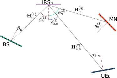
a passive eavesdropper (or malicious node, MN), whose ULA is composed of isotropic antenna elements. The goal of the MN is to eavesdrop the communication from the BS towards one of the legitimate UE, by intercepting the signals reflected by the IRSs. To do so, the MN exploits the directivity provided by its ULA by pointing it towards the IRS serving the UE that the MN wants to eavesdrop.
In the remainder of this section, we characterize the main elements of the system we consider, namely, the channel and IRSs (Sec. II-A), the nodes and their behavior (Sec. II-B), the metrics we consider (Sec. II-C), and the time dimension (Sec. II-D).
II-A Channel and IRS
The elements of the ULAs and of the IRSs are assumed to be separated by where is the wavelength of the signal carrier. We assume that no line-of-sight (LoS) path exists between the BS and the UEs. However, communication is made possible by the ability of the IRSs to reflect the BS signal towards the users [13]. All IRSs and user nodes, including the MN, are assumed to have the same height above ground, as depicted in Figure 1. This assumption allows simplifying the discussion and the notation while capturing the key aspects of the system. In the following, we detail the communication chain as well as the channel model.
Communication channel. While in many works dealing with GHz communications, the channel matrix connecting two multi-antenna devices is often modeled according to Rayleigh or Rice distributions, in the THz bands the channel statistic is not yet completely characterized. Moreover, at such high frequencies the signal suffers from strong free-space attenuation, and is blocked even by small solid obstacles. In practice, the receiver needs to be in line-of-sight (LoS) with the transmitter to be able to communicate. Also, recent studies [14] highlight that already at sub-THz frequencies all scattered components and multipath effects can be neglected. This conclusion is also supported by the fact that, typically, both the transmitter and the receiver employ massive beamforming techniques in order to concentrate the signal energy along a specific direction and compensate for high path losses. In such conditions, the channel matrix between any two devices can thus be modeled as:
| (1) |
where the scalar takes into account large scale fading effects due to, e.g., obstacles temporarily crossing the LoS path between transmitter and receiver. The coefficient instead accounts for the attenuation and phase rotation due to propagation. More specifically, let be the distance between the transmitting and the receiving device and be the array gain of one of them. Then the expression for is given by:
| (2) |
where is the effective area of the other device. Finally, and are norm-1 vectors representing, respectively, the spatial signatures of the receive and transmit antenna arrays. The spatial signature of a ULA composed of (BS,UE,MN) isotropic elements spaced by and observed from an angle (measured with respect to a direction orthogonal to the ULA), is given by the size- vector , whose -th element is given by
| (3) |
This relation applies to devices equipped with ULAs such as the BS, the UEs and the MN. However, it can also be applied to IRSs since their planar configuration can be viewed as a superposition of several ULAs.
IRS characterization. IRSs are made of meta-atoms (modeled as elementary spherical scatterer) whose scattered electromagnetic field holds in the far-field regime [15, 16]. The -th IRS, , is composed of meta-atoms arranged in an square grid. The area of the -th IRS is, thus, given by . The meta-atom at position in the -th IRS applies a (controlled) continuous phase shift, to the signal impinging on it. In many works that assume rich scattering communication channels, such phase-shifts are independently optimized in order to maximize some performance figures. However, under the channel model in (1), phase-shifts are related to each other [17, 18] according to the linear equation:
| (4) |
where and control, respectively, the direction and the phase of the reflected signal. For simplicity, we arrange the phase shifts in the diagonal matrix
where , denotes the Kronecker product, and is the identity matrix of size . As an example, let be the angle of arrival (AoA) of the BS signals on the -th IRS and let be the direction of the -th IRS as observed from the -th IRS (see Figure 1). Then, in order to let the -IRS reflect the BS signal towards the -th UE, we set [13]
| (5) |
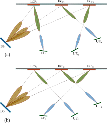
In a practical case, a given IRS serves a single UE; thus, we define as permutation a mapping between the set of UEs and the set of IRSs:
Under this map, IRS forwards the BS signal towards the -th UE and, by symmetry, the -th UE points its beam towards the -th IRS. The number of possible permutations (or maps) is then and its set is denoted by . Moreover, we also denote by the matrix of the -IRS phase-shifts under the permutation . An example of possible permutations for a network composed of IRSs and UEs is depicted in Figure 2.
II-B Network nodes
Base station. The BS transmit a signal with bandwidth and wavelength . Such signal contains data streams, one for each UE. Let be the zero-mean unit variance Gaussian complex i.i.d. random symbol generated for the -th stream at a given time. Also, let , be the beamforming vector employed for transmitting . Then, the signal transmitted by the BS is given by:
| (6) |
where , . We assume that the total transmit power is limited by , where denotes the Frobenius norm.
Legitimate receivers (UEs). The signal received by the -th UE under the -th map is given by
| (7) |
where is additive Gaussian complex noise, whose power spectral density is . is the signal bandwidth and is the beamforming vector at the -th UE. According to the channel model in (1), is the channel connecting the BS to the -th IRS and is the channel matrix connecting the -th IRS to the -th UE. In particular, we have , , , , and . In the above expressions, denotes the Kronecker product and is an all-ones column vectors of size . Notice that, by assuming that all network nodes have the same height over the ground, the -th IRS can be viewed as a superposition of identical ULAs. Thus, its spatial signature can be written in compact form by using the Kronecker product, as indicated above.
The angles , , , and are specified in Figure 1. Furthermore, and where and are, respectively, the distance between the BS and the -th IRS, and the distance between the -th IRS and the -th UE.
We assume that the UE ULA is only capable of analog beamforming. Thus, the norm-1 vector is defined as where , i.e., the beam generated by the -th UE ULA points to the -th IRS. By collecting in the vector the signals received by the UEs and by recalling (6), we can write
| (8) | |||||
where and .
Malicious node. By eavesdropping the communication, the MN acts as an additional receiver. When the -th map is applied and the MN ULA points to the -th IRS, the received signal can be written similarly to (7), as
| (9) | |||||
where is the channel matrix connecting the -th IRS to the MN, , , (see Figure 1). Also, where is the distance between the MN and the -th IRS. Finally, represents the additive noise at the receiver and is the norm-1 beamforming vector.
II-C Metrics of interest
For each combination of IRS-to-UE assignment, we are interested in deriving two main metrics, namely, the SINR (hence, the data rate) and the secrecy rate.
The SINR achieved at each UE depends on the precoding strategy employed at the BS, i.e., on the choice of the precoder . For example, the zero-forcing (ZF) precoder permits to remove the inter-user interference while providing good (although not optimal) performance. Under the -th map, , the ZF precoder is obtained by solving for the equation where is an arbitrary positive diagonal matrix and the scalar should be set so as to satisfy the power constraint . Its expression is given by:
| (10) |
where is the Moore-Penrose pseudo-inverse of . Then, the SINR at the -th UE is given by,
| (11) |
Similarly, we can write the SINR at the MN when the latter points its ULA to the -th IRS while eavesdropping the -th data stream, as
| (12) |
where is the -th column of whose expression is given by (10). The data rate for UE under the -map can be computed as
| (13) |
Finally, the secrecy rate (SR) obtained when the MN eavesdrops the -th stream by pointing its antenna to the -th IRS, under the -map, is given by
| (14) |
The operator in (14) is required since, under certain circumstances, might be larger than .
II-D Permutations and time
We define a set of IRS-to-UE assignments as a permutation; intuitively, each permutation corresponds to one way to serve the users. Given the set of all possible permutations, the BS chooses a set of permutations to activate, as well as a criterion that legitimate nodes shall follow to determine the next permutation to move to. In other words, legitimate nodes will always know the next permutation to use (e.g., because they follow the same hash chain [19]), while the eavesdropper can not. We further assume that all chosen permutations are used with equal probability, and that they are notified to legitimate users in a secure manner, while the eavesdropper has no way of knowing the next permutation in advance. As noted earlier, hash chains allow to attain both goals.
Concerning time, we normalize everything to the time it takes to receivers (legitimate or not) to switch from one configuration to another, and call that one time unit. The BS also sets the number of time units the legitimate users should stay with each permutation. As for the eavesdropper, we consider the most unfavorable scenario for the legitimate users and assume that MN has already estimated the probability with which its victim is served by each IRS, and that it can leverage such information.
III Problem Formulation and Solution Concept
In this section, we formulate the problem of optimizing the decisions made by the BS, i.e., the choice of the permutations to use and the time to wait before switching to the next permutation, in order to obtain the best possible secrecy rate and the required data rate.
Given the set of permutations, we can indicate with the IRS used to serve user under permutation . We also know the rate , i.e., the rate experienced by user under combination , as well as , i.e., the secrecy rate obtained under permutation when the victim is user and the eavesdropper is listening to IRS . Further, let identify the eavesdropping victim.
Given , we have to decide which permutations to use, by setting binary variables ; also, let be the set of used permutations. From the decisions , we can write the probability that user is served through IRS under any of the chosen permutation, i.e.,
| (15) |
The second decision to make is the time for which each permutation is applied before switching to a new one. If the time needed for switching permutation is equal to one time unit and the communication is paused during such switching time, (i.e., every ), the average rate for each legitimate user is given by:
| (16) |
As expected, (16) tells us that having a small , i.e., switching between permutations too frequently, hurts the performance.
Moving to the eavesdropper, its objective is to have the smallest possible secrecy rate (SR) for its victim . There are two strategies it can follow towards this end:
-
•
static: always pointing to the IRS that is most frequently used to serve the victim , i.e., , or
-
•
dynamic: “invest” time units to try all IRSs, identify the one serving the victim , and then point towards it.
In the first case, the resulting SR is given by:
| (17) |
while in the latter case, the SR is:
| (18) |
if , and otherwise.
The quantity within square brackets in (18) comes from the fact that, for each permutation (i.e., each time units), the eavesdropper spends units trying all IRSs (during which the secrecy rate will be , i.e., complete secrecy), and units experiencing the minimum secrecy rate across all IRSs.
In both cases, SR values are subordinate to the fact that the BS is transmitting – clearly, if there is no transmission, there can be no secrecy rate. Also notice how we must write SR values as dependent upon the eavesdropping victim : indeed, the eavesdropper knows who its victim is, while legitimate users do not.
The eavesdropper will choose the strategy that best suits it, i.e., results in the lowest secrecy rate. It follows that the resulting secrecy rate is:
The network high-level goal is to maximize the secrecy rate, so long as all legitimate users get at least an average rate :
| (19) |
| (20) |
It is interesting to remark how objective (19) must be stated in a max-min form: indeed, since the BS does not know who the eavesdropping victim is, it aims at maximizing the secrecy rate in the worst-case scenario, in which the node with the lowest SR is indeed the victim.
Owing to the complexity of choosing the optimal set of permutations to use, in the following we will study three heuristics to make such a decision, based upon (i) data rate, (ii) IRS usage, or (iii) random. Indeed, as further discussed next, our goal is to investigate the trade-off existing between secrecy rate and system throughput when a switching-configuration scheme is adopted at the IRS in order to achieve the above objective.
IV Performance Evaluation
In this section, we seek to characterize and understand the possible trade-offs between the data rate and secrecy rate, and how the decisions we make, i.e., the choice of and , influence both.
In order to obtain clear, easy-to-interpret results, we focus on a small scale scenario including:
-
•
one BS, placed at coordinates , equipped with antennas; in our setting the transmit power is dBm, the signal wavelength mm, (corresponding to the carrier frequency 100 GHz), the signal bandwidth is GHz, and dBm/Hz. Moreover, in (10) we set so that all UEs experience the same SNR.
-
•
UEs, randomly distributed over a m2 surface, and equipped with antennas;
-
•
IRSs of size meta-atoms, randomly placed over the northern wall;
-
•
an eavesdropper, randomly placed within 1 m from its intended victim, which is always UE (i.e., ). The eavesdropper is also equipped with antenna elements.
As , there are possible permutations. Since we assume that no direct LoS communication is possible between the BS and the UEs, each UE is always associated with an IRS that forwards to the UE the signal from the BS. Finally we conside and, for simplicity, ignore fading effects.
Throughout our performance evaluation, we compare the following approaches to choose the set :
-
•
best rate: the permutations with the highest data rate are selected;
-
•
uniform IRS usage: the permutations are chosen so that each UE is served by each IRS with (approximately) the same probability, with ties broken by selecting the highest-rate permutation;
-
•
random: permutations are chosen at random, with uniform probability.
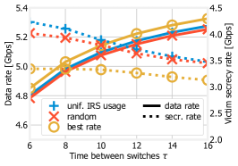
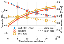
Figure 3 shows the data rate and secrecy rate, represented by solid and dotted lines respectively, as a function of the interval between configuration changes, and for different numbers of active permutations, i.e., different values of . A first aspect we observe is that moving towards larger values of , i.e., a higher number of active permutations, decreases the data rate while increasing the secrecy rate. The reason for the former effect can be seen from the expression of the average rate expression (16), which is maximum when only one permutation is active, namely, the one with the highest rate. Conversely, having more active permutations makes the work of the malicious node harder, hence, it results in a higher secrecy rate.
Furthermore, it is possible to see how the average rate (solid lines in the plots) increases for higher values of , i.e., when permutations are kept for a longer time. This is consistent with (16); intuitively, if the same network configuration is kept for a longer time, the effect of configuration switches is less significant. For similar reasons, the secrecy rate (dotted lines in the plots) decreases as increases: once the eavesdropper has identified the best IRS to point to, a higher value of means that it has more time to successfully intercept the communication.
Comparing the different approaches to choose , it is possible to once more observe the intrinsic conflict between data rate and secrecy rate. The best rate approach results, predictably, in the highest data rate, but also in a very low secrecy rate. On the other hand, the uniform IRS usage approach yields a very good secrecy rate, at the cost of a data rate which barely exceeds that of random.
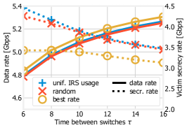
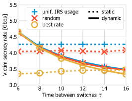
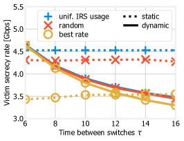
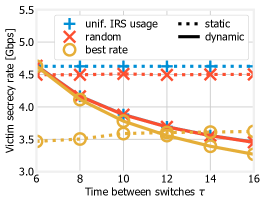
We now focus on the eavesdropper and its behavior. To this end, Figure 4 portrays the secrecy rate resulting from the two eavesdropping strategies discussed in Sec. III, namely, static (dotted lines) and dynamic (solid lines). It is clear that the dynamic strategy results in a very high secrecy rate when is small, i.e., permutations are changed frequently, and becomes more advantageous (for the eavesdropper) as increases. Such a behavior makes intuitive sense: the dynamic strategy is predicated on investing time units to find out the best IRS to point to, and doing so is pointless if the configuration will change soon afterwards. As for the static strategy, the resulting secrecy rate does not depend, as per (17), upon , hence, its performance is relatively constant.
Interestingly, the value of for which the curves in Figure 4 overlap, i.e., the eavesdropper will move from the static to the dynamic strategy, depends upon the number of active permutation, as well as upon the approach followed to choose them. This further highlights the nontrivial way in which the decisions of the legitimate and malicious nodes interact, even in comparatively simple scenarios like the one we consider.
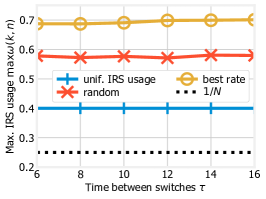
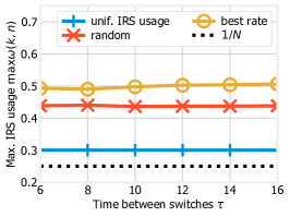
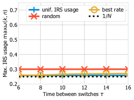
Last, Figure 5 depicts the maximum IRS usage, i.e., the quantity ; such a quantity appears in (17), hence, it is linked to how strong the static strategy is. Intuitively, keeping as low as possible makes the static strategy less beneficial for the eavesdropper; since, as per Figure 4, the static strategy is often the most effective, doing so has the potential to increase the overall secrecy rate, especially for low values of . Indeed, we can see from Figure 5 that the uniform IRS usage strategy results in the smallest maximum IRS usage, which correspond to the highest secrecy rates in Figure 3 and Figure 4.
This further confirms the notion emerging from our whole performance evaluation, namely, that selecting multiple active permutations and frequently switching between them is necessary to thwart the eavesdropper, however, both actions come at a price in terms of network performance, i.e., data rate. This, in turn, highlights the need for a deeper understanding of the effects of the decisions made by both the BS and the malicious nodes, and for algorithms able to leverage such insight.
V Conclusions
We considered a base station transmitting towards users through the help of intelligent reflecting surfaces, and the presence of a passive eavesdropper overhearing the data stream destined to a legitimate user. Given that the network aims at maximizing the secrecy rate in the system, we consider a solution strategy that, leveraging the different possible IRS configurations, lets IRS and legitimate users switch from one configuration to another with a given periodicity. Importantly, such a scheme (i) exhibits low-complexity, (ii) is suitable for scenarios where the nodes have a limited number of antenna elements, and (iii) provides high secrecy rate at a small cost in terms of data rate degradation for legitimate users. The latter point is demonstrated through a numerical evaluation, which aims at studying the way IRSs are used and at highlighting the trade-off existing between secrecy rate and system throughput.
References
- [1] J. Qiao and M.-S. Alouini, “Secure transmission for intelligent reflecting surface-assisted mmwave and terahertz systems,” IEEE Wireless Communications Letters, vol. 9, pp. 16–32, 2020.
- [2] I. F. Akyildiz, J. M. Jornet, and C. Han, “Terahertz band: next frontier for wireless communications,” Physical Communication, vol. 12, pp. 16–32, 2014.
- [3] Q. Wu and R. Zhang, “Towards smart and reconfigurable environment: Intelligent reflecting surface aided wireless network,” IEEE Communications Magazine, pp. 106–112, January 2020.
- [4] M. Di Renzo, M. Debbah, D.-T. Phan-Huy, A. Zappone, M.-S. Alouini, C. Yuen, V. Sciancalepore, G. C. Alexandropoulos, J. Hoydis, H. Gacanin et al., “Smart radio environments empowered by reconfigurable ai meta-surfaces: An idea whose time has come,” EURASIP Journal on Wireless Communications and Networking, 2019.
- [5] C. Liaskos, S. Nie, A. Tsioliaridou, A. Pitsillides, S. Ioannidis, and I. Akyildiz, “A new wireless communication paradigm through software-controlled metasurfaces,” IEEE Communications Magazine, 2018.
- [6] C. Liaskos, A. Tsioliaridou, A. Pitsillides, S. Ioannidis, and I. Akyildiz, “Using any surface to realize a new paradigm for wireless communications,” Communications of the ACM, 2018.
- [7] M. Alsharif, A. K. amd M.A. Albreem, S. Chaudhry, M. Zia, and S. Kim, “Sixth generation (6g) wireless networks: Vision, research activities, challenges and potential solutions,” Symmetry, vol. 12, no. 4:676, 2020.
- [8] X. Yu, D. Xu, and R. Schober, “Enabling secure wireless communications via intelligent reflecting surfaces,” arXiv preprint arXiv:1904.09573v3, 2020.
- [9] G. Zhou, C. Pan, H. Ren, K. Wang, A. Nallanathan, and K.-K. Wong, “User cooperation for irs-aided secure swipt mimo: Active attacks and passive eavesdropping,” arXiv preprint arXiv:2006.05347, 2020.
- [10] X. Guan, Q. Wu, and R. Zhang, “Intelligent reflecting surface assisted secrecy communication: Is artificial noise helpful or not?” IEEE Wireless Communications Letters, 2020.
- [11] A. Bereyhi, S. Asaad, R. R. Müller, R. F. Schaefer, and H. V. Poor, “Secure transmission in irs-assisted mimo systems with active eavesdroppers,” arXiv preprint arXiv:2010.07989, 2020.
- [12] L. Dong and H.-M. Wang, “Secure mimo transmission via intelligent reflecting surface,” IEEE Wireless Communications Letters, 2020.
- [13] A. Tarable, F. Malandrino, L. Dossi, R. Nebuloni, G. Virone, and A. Nordio, “Meta-Surface Optimization in 6G Sub-THz Communications,” in IEEE ICC Workshop on Terahertz Communications, 2020.
- [14] Y. Xing, O. Kanhere, S. Ju, and T. S. Rappaport, “Indoor wireless channel properties at millimeter wave and sub-terahertz frequencies,” IEEE Global Communications Conference, 2019.
- [15] M. Di Renzo, F. Habibi Danufane, X. Xi, J. de Rosny, and S. Tretyakov, “Analytical modeling of the path-loss for reconfigurable intelligent surfaces – anomalous mirror or scatterer ?” in 2020 IEEE 21st International Workshop on Signal Processing Advances in Wireless Communications (SPAWC), 2020, pp. 1–5.
- [16] Ö. Özdogan, E. Björnson, and E. G. Larsson, “Intelligent reflecting surfaces: Physics, propagation, pathloss modeling,” IEEE Wireless Communications Letters, vol. 9, no. 5, 2020.
- [17] M. Dunna, C. Zhang, D. Sievenpiper, and D. Bharadia, “Scattermimo: Enabling virtual mimo with smart surfaces,” MobiCom ’20: Proceedings of the 26th Annual International Conference on Mobile Computing and Networking, 2020.
- [18] Q. Wu and R. Zhang, “Intelligent reflecting surface enhanced wireless network: Joint active and passive beamforming design,” IEEE Globecom, pp. 1–6, 2018.
- [19] S. Hussain, M. S. Rahman, and L. T. Yang, “Key predistribution scheme using keyed-hash chain and multipath key reinforcement for wireless sensor networks,” in IEEE PerCom, 2009.