Reflection and Relay Dual-Functional RIS Assisted MU-MISO Systems thanks: This work is supported in part by the National Natural Science Foundation of China (Grant No. 61971088, 62071083, U1808206, and U1908214), the Natural Science Foundation of Liaoning Province (Grant No. 2020-MS-108), in part by the Fundamental Research Funds for the Central Universities (Grant No. DUT20GJ214, DUT21GJ208 and DUT20RC(3)029), in part by Dalian Science and Technology Innovation Project (Grant No. 2020JJ25CY001), and in part by the Open Research Fund of National Mobile Communications Research Laboratory, Southeast University (Grant No. 2021D08).

Yanan Ma, Rang Liu, Ming Li∗†, Yang Liu, Qingqing Wu and Qian Liu


Dalian University of Technology, Dalian, Liaoning 116024, China
E-mail: {mayanan, liurang}@mail.dlut.edu.cn,
{mli, yangliu_613, qianliu}@dlut.edu.cn
Southeast University, Nanjing, Jiangsu 210096, China University of Macau, Macau, 999078, China
E-mail: qingqingwu@um.edu.mo
Abstract

Reconfigurable intelligent surface (RIS) is a promising solution to adaptively manipulate wireless propagation with low-cost passive devices. However, the traditional passive RIS can offer sufficient signal strength only when receivers are very close to it. Moreover, the users at the back side of it cannot be well served due to its reflective property. In this paper we introduce a novel reflection and relay dual-functional RIS architecture, which can simultaneously realize passive reflection and active relay functionalities. The problem of joint transmit beamforming and dual-functional RIS design is investigated to maximize the achievable sum-rate of a multiuser multiple-input single-output (MU-MISO) system. Based on fractional programming (FP) theory and majorization-minimization (MM) technique, we propose an efficient iterative transmit beamforming and RIS design algorithm. Simulation results demonstrate the superiority of the introduced dual-functional RIS architecture and the effectiveness of the proposed algorithm.

Index Terms:
Reconfigurable intelligent surfaces, beamforming, relay, fractional programming (FP), majorization-minimization (MM).

I Introduction

Reconfigurable intelligent surface (RIS) has been proposed as an inherent component of future wireless communication systems owing to its superior ability of shaping the wireless environment [1]-[10]. However, due to “double fading” effect (i.e., the equivalent path loss of the transmitter-RIS-receiver link is the product of the path losses of transmitter-RIS link and RIS-receiver link, which is usually an order-of-magnitude larger than that of the direct link), RIS should be deployed close to either the base station (BS) or users to effectively improve communication quality-of-service (QoS) [1], [2]. Besides, the research on the comparison of RIS and relay illustrates that RIS can be easily outperformed by conventional full-duplex (FD) amplify-and-forward (AF) relay unless very large RIS is employed [3], [4]. However, very large number of reflecting elements will lead to high training overhead for channel estimation and high complexity of beamforming designs [5]. Meanwhile, the control of a large RIS will also become a difficult task.

Moreover, the users at the back of RIS cannot be well served due to its reflective property. The service coverage of RIS is limited to only one side of the surface. To overcome this limitation, simultaneously transmitting and reflecting RIS (STAR-RIS) was proposed [6], [7], which can reflect and transmit the incident signals to serve the users in front of RIS or behind it. Thus, the STAR-RIS can provide service for users at both sides of it and improve coverage in a reflective and transmissive way [8]. However, the performance improvement of passive STAR-RIS is still limited due to severe signal attenuation.

In order to overcome the double fading and extend the coverage, the authors in [9] proposed a novel relay-aided RIS architecture consisting of two RIS surfaces connected via an FD relay, which can achieve the same performance with conventional RIS while only requiring much fewer reconfigurable elements. However, they only consider single-input single-output (SISO) system and derive the theoretical upper bound of achievable rate. The designs of BS beamforming and RIS reflection have not been well investigated. Another limitation of this work is that the first RIS is adjusted to reflect the signal towards the relay only and cannot simultaneously serve the users around it, which does not take the full use of RIS. In [10], [11], the authors proposed a semi-active RIS-aided architecture, which can not only passively reflect the signal, but also actively amplify it at the same time. However, the practical implementation of this hybrid-RIS remains an open problem, while it needs expensive radio frequency (RF) chains. Active RIS [2], [12] has recently been proposed to overcome the practical implementation problems of passive RIS. However, the hardware implementation is still an issue needs to be addressed.

In this paper we propose a novel reflection and relay dual-functional RIS architecture to overcome the double fading effect, enhance the coverage and reduce hardware complexity. The dual-functional RIS unites two RISs back-to-back with a full-duplex amplifier and can simultaneously realize passive reflection and active relay functionalities. Particularly, one RIS passively adjusts its phase shifters to serve the users close to it and at the same side as this RIS. Meanwhile, the signal is amplified and transmitted by the other RIS to serve the users far away from BS/RIS and at the back side of it. Based on the proposed dual-functional RIS architecture, a sum-rate maximization problem is considered for an MU-MISO system. A joint transmit beamforming and RIS reflection design algorithm is developed based on fractional programming (FP) theory and majorization-minimization (MM) technique. The superiority of the dual-functional RIS architecture and the effectiveness of the proposed design algorithm are validated by simulation results.

II System Model

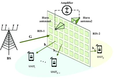
We consider dual-functional RIS assisted wireless communication system as illustrated in Fig. 1. The BS equipped with N𝑁N antennas communicates to K𝐾K single-antenna users with the aid of a dual-functional RIS. Specifically, the proposed dual-functional RIS is composed of two conventional passive RISs connected via a full-duplex amplifier. Each conventional RIS comprises a large number of passive elements, each being able to reflect the incident signal with a controllable phase-shift. As shown in Fig. 1, user-1, …, user-(K1)𝐾1{(K-1)}, are located around RIS and served by the RIS facing them (which is labelled as RIS-1 in Fig. 1). Meanwhile, the K𝐾K-th user cannot receive sufficient strong signals from the BS or RIS-1 due to the fact that it is located in the opposite of it and the direct link to BS is blocked. Therefore, we propose the dual-functional RIS scheme to provide satisfactory QoS to all users, no matter where they are located. Specifically, the signal from BS is first reflected by RIS-1 to horn antenna-1, then amplified and emitted to the second (right) side of the RIS (labeled as RIS-2), which transmits the signal towards the K𝐾K-th user. We assume that there exists no direct link from RIS-1 to the K𝐾K-th user and vice versa.

Refer to caption
Figure 1: The proposed reflection and relay dual-functional RIS architecture in an MU-MISO system.
gR(𝚽1,𝚽2,𝐰k,𝜸,𝝉)=k=1Klog2(1+γk)k=1Kγk+k=1K1(21+γk{τk𝐡kH𝚽1𝐆𝐰k}|τk|2i=1K|𝐡kH𝚽1𝐆𝐰i|2|τk|2σk2)subscript𝑔Rsubscript𝚽1subscript𝚽2subscript𝐰𝑘𝜸𝝉superscriptsubscript𝑘1𝐾subscript21subscript𝛾𝑘superscriptsubscript𝑘1𝐾subscript𝛾𝑘superscriptsubscript𝑘1𝐾121subscript𝛾𝑘superscriptsubscript𝜏𝑘superscriptsubscript𝐡𝑘𝐻subscript𝚽1subscript𝐆𝐰𝑘superscriptsubscript𝜏𝑘2superscriptsubscript𝑖1𝐾superscriptsuperscriptsubscript𝐡𝑘𝐻subscript𝚽1subscript𝐆𝐰𝑖2superscriptsubscript𝜏𝑘2superscriptsubscript𝜎𝑘2g_{\mathrm{R}}(\bm{\Phi}_{1},\bm{\Phi}_{2},\mathbf{w}_{k},\bm{\gamma},\bm{\tau})=\sum_{k=1}^{K}\log_{2}\left(1+\gamma_{k}\right)-\sum_{k=1}^{K}\gamma_{k}\\ +\sum_{k=1}^{K-1}(2\sqrt{1+\gamma_{k}}\Re\left\{\tau_{k}^{\ast}\mathbf{h}_{k}^{H}\bm{\Phi}_{1}\mathbf{G}\mathbf{w}_{k}\right\}-\left|\tau_{k}\right|^{2}\sum_{i=1}^{K}\left|\mathbf{h}_{k}^{H}\bm{\Phi}_{1}\mathbf{G}\mathbf{w}_{i}\right|^{2}-\left|\tau_{k}\right|^{2}{\sigma_{k}^{2}})\\
+2β(1+γK){τK𝐡KH𝚽2𝐠r𝐠tH𝚽1𝐆𝐰K}|τK|2βi=1K|𝐡KH𝚽2𝐠r𝐠tH𝚽1𝐆𝐰i|2|τK|2ξK22𝛽1subscript𝛾𝐾superscriptsubscript𝜏𝐾superscriptsubscript𝐡𝐾𝐻subscript𝚽2subscript𝐠rsuperscriptsubscript𝐠t𝐻subscript𝚽1subscript𝐆𝐰𝐾superscriptsubscript𝜏𝐾2𝛽superscriptsubscript𝑖1𝐾superscriptsuperscriptsubscript𝐡𝐾𝐻subscript𝚽2subscript𝐠rsuperscriptsubscript𝐠t𝐻subscript𝚽1subscript𝐆𝐰𝑖2superscriptsubscript𝜏𝐾2superscriptsubscript𝜉𝐾2+2\sqrt{\beta\left(1+\gamma_{K}\right)}\Re\left\{\tau_{K}^{\ast}\mathbf{h}_{K}^{H}\bm{\Phi}_{2}\mathbf{g}_{\mathrm{r}}\mathbf{g}_{\mathrm{t}}^{H}\bm{\Phi}_{1}\mathbf{G}\mathbf{w}_{K}\right\}-\left|\tau_{K}\right|^{2}\beta\sum_{i=1}^{K}\left|\mathbf{h}_{K}^{H}\bm{\Phi}_{2}\mathbf{g}_{\mathrm{r}}\mathbf{g}_{\mathrm{t}}^{H}\bm{\Phi}_{1}\mathbf{G}\mathbf{w}_{i}\right|^{2}-\left|\tau_{K}\right|^{2}\xi_{K}^{2} (10)

Each side of the dual-functional RIS has M𝑀M passive reconfigurable elements, whose phase shifters can be adjusted by a controller through a dedicated control link. We define the reflection coefficient vector ϕ1[ejθ1,1,,ejθ1,M]Tsubscriptbold-italic-ϕ1superscriptsuperscript𝑒𝑗subscript𝜃11superscript𝑒𝑗subscript𝜃1𝑀𝑇\bm{\phi}_{1}\triangleq\left[e^{j\theta_{1,1}},\ldots,e^{j\theta_{1,M}}\right]^{T} and reflection matrix 𝚽1diag(ϕ1)subscript𝚽1diagsubscriptbold-italic-ϕ1\bm{\Phi}_{1}\triangleq\operatorname{diag}\left(\bm{\phi}_{1}\right), with θ1,msubscript𝜃1𝑚\theta_{1,m} denoting the phase-shift of the m𝑚m-th element of RIS-1. Similarly, the notations ϕ2subscriptbold-italic-ϕ2\bm{\phi}_{2} and 𝚽2subscript𝚽2\bm{\Phi}_{2} are defined in the same way to represent the phase-shift of RIS-2. We consider a challenging scenario where no direct link exists between the transmitter and the users due to, for example, the blockage of buildings. Since the k𝑘k-th user, k=1,,K1𝑘1𝐾1k=1,\cdots,K-1, is solely served by reflective RIS-1, the received signal at these users can be modeled as

yk=𝐡kH𝚽1𝐆i=1K𝐰isi+nk,k=1,,K1,formulae-sequencesubscript𝑦𝑘superscriptsubscript𝐡𝑘𝐻subscript𝚽1𝐆superscriptsubscript𝑖1𝐾subscript𝐰𝑖subscript𝑠𝑖subscript𝑛𝑘𝑘1𝐾1y_{k}=\mathbf{h}_{k}^{H}\bm{\Phi}_{1}\mathbf{G}\sum_{i=1}^{K}\mathbf{w}_{i}s_{i}+n_{k},~{}~{}~{}k=1,\ldots,K-1, (1)

where si,i=1,,Kformulae-sequencesubscript𝑠𝑖𝑖1𝐾s_{i}\in\mathbb{C},i=1,\ldots,K, is the transmitted symbol, 𝔼{|si|2}=1𝔼superscriptsubscript𝑠𝑖21\mathbb{E}\{\left|s_{i}\right|^{2}\}=1, 𝐰iNsubscript𝐰𝑖superscript𝑁\mathbf{w}_{i}\in\mathbb{C}^{N} is the beamformer at the BS for the i𝑖i-th user, 𝐆M×N𝐆superscript𝑀𝑁\mathbf{G}\in\mathbb{C}^{M\times N} and 𝐡kMsubscript𝐡𝑘superscript𝑀\mathbf{h}_{k}\in\mathbb{C}^{M} denote the channels from BS to RIS-1, from RIS-1 to user-k𝑘k, respectively, and nk𝒞𝒩(0,σk2)similar-tosubscript𝑛𝑘𝒞𝒩0subscriptsuperscript𝜎2𝑘n_{k}\sim\mathcal{CN}\left(0,\sigma^{2}_{k}\right) denotes the complex additive white Gaussian noise with variance σk2subscriptsuperscript𝜎2𝑘\sigma^{2}_{k} at user-k𝑘k. We assume that the channel state information (CSI) of all channels involved is perfectly known. The practical CSI acquisition techniques can be found in [13]. Thus, the signal-to-interference-plus-noise ratio (SINR) of the k𝑘k-th user can be expressed as

SINRk=|𝐡kH𝚽1𝐆𝐰k|2ikK|𝐡kH𝚽1𝐆𝐰i|2+σk2,k=1,,K1.formulae-sequencesubscriptSINR𝑘superscriptsuperscriptsubscript𝐡𝑘𝐻subscript𝚽1subscript𝐆𝐰𝑘2superscriptsubscript𝑖𝑘𝐾superscriptsuperscriptsubscript𝐡𝑘𝐻subscript𝚽1subscript𝐆𝐰𝑖2superscriptsubscript𝜎𝑘2𝑘1𝐾1\displaystyle\mathrm{SINR}_{k}=\frac{|\mathbf{h}_{k}^{H}\bm{\Phi}_{1}\mathbf{G}\mathbf{w}_{k}|^{2}}{\sum_{i\neq k}^{K}\left|\mathbf{h}_{k}^{H}\bm{\Phi}_{1}\mathbf{G}\mathbf{w}_{i}\right|^{2}+{\sigma_{k}^{2}}},k=1,\ldots,K-1. (2)

Similarly, the received signal at the input of amplifier via the horn antenna-1 can be written as

yr=𝐠tH𝚽1𝐆i=1K𝐰isi+n0,subscript𝑦rsuperscriptsubscript𝐠t𝐻subscript𝚽1𝐆superscriptsubscript𝑖1𝐾subscript𝐰𝑖subscript𝑠𝑖subscript𝑛0y_{\mathrm{r}}=\mathbf{g}_{\mathrm{t}}^{H}\bm{\Phi}_{1}\mathbf{G}\sum_{i=1}^{K}\mathbf{w}_{i}s_{i}+n_{0}, (3)

where n0𝒞𝒩(0,σ02)similar-tosubscript𝑛0𝒞𝒩0superscriptsubscript𝜎02n_{0}\sim\mathcal{CN}\left(0,\sigma_{0}^{2}\right) denotes the thermal noise with variance σ02superscriptsubscript𝜎02\sigma_{0}^{2}, 𝐠tMsubscript𝐠tsuperscript𝑀\mathbf{g}_{\mathrm{t}}\in\mathbb{C}^{M} denotes the channel from RIS-1 to horn antenna-1. Then, the signal yrsubscript𝑦ry_{\mathrm{r}} is amplified and transmitted by RIS-2 towards the K𝐾K-th user, whose received signal can be written as

yK=subscript𝑦𝐾absent\displaystyle y_{K}= β𝐡KH𝚽2𝐠r(𝐠tH𝚽1𝐆i=1K𝐰isi+n0)+nK𝛽superscriptsubscript𝐡𝐾𝐻subscript𝚽2subscript𝐠rsuperscriptsubscript𝐠t𝐻subscript𝚽1𝐆superscriptsubscript𝑖1𝐾subscript𝐰𝑖subscript𝑠𝑖subscript𝑛0subscript𝑛𝐾\displaystyle\sqrt{\beta}\mathbf{h}_{K}^{H}\bm{\Phi}_{2}\mathbf{g}_{\mathrm{r}}\left(\mathbf{g}_{\mathrm{t}}^{H}\bm{\Phi}_{1}\mathbf{G}\sum_{i=1}^{K}\mathbf{w}_{i}s_{i}+n_{0}\right)+n_{K} (4)
=\displaystyle= β𝐡KH𝚽2𝐠r𝐠tH𝚽1𝐆i=1K𝐰isi+β𝐡KH𝚽2𝐠rn0+nK,𝛽superscriptsubscript𝐡𝐾𝐻subscript𝚽2subscript𝐠rsuperscriptsubscript𝐠t𝐻subscript𝚽1𝐆superscriptsubscript𝑖1𝐾subscript𝐰𝑖subscript𝑠𝑖𝛽superscriptsubscript𝐡𝐾𝐻subscript𝚽2subscript𝐠rsubscript𝑛0subscript𝑛𝐾\displaystyle\sqrt{\beta}\mathbf{h}_{K}^{H}\bm{\Phi}_{2}\mathbf{g}_{\mathrm{r}}\mathbf{g}_{\mathrm{t}}^{H}\bm{\Phi}_{1}\mathbf{G}\sum_{i=1}^{K}\mathbf{w}_{i}s_{i}+\sqrt{\beta}\mathbf{h}_{K}^{H}\bm{\Phi}_{2}\mathbf{g}_{\mathrm{r}}n_{0}+n_{K},

where 𝐠rMsubscript𝐠rsuperscript𝑀\mathbf{g}_{\mathrm{r}}\in\mathbb{C}^{M} denotes the channel from horn antenna-2 to RIS-2 and β𝛽\beta denotes the amplification gain which is assumed to be a constant. Considering that the RISs and the horn antennas are deployed very closely, we use near-field propagation model to describe channels 𝐠tsubscript𝐠t\mathbf{g}_{\mathrm{t}} and 𝐠rsubscript𝐠r\mathbf{g}_{\mathrm{r}} [14], [15], whose details are omitted due to space limitations. Thus, the SINR of the K𝐾K-th user can be expressed as

SINRK=β|𝐡KH𝚽2𝐠r𝐠tH𝚽1𝐆𝐰K|2βiKK|𝐡KH𝚽2𝐠r𝐠tH𝚽1𝐆𝐰i|2+ξK2,subscriptSINR𝐾𝛽superscriptsuperscriptsubscript𝐡𝐾𝐻subscript𝚽2subscript𝐠rsuperscriptsubscript𝐠t𝐻subscript𝚽1subscript𝐆𝐰𝐾2𝛽superscriptsubscript𝑖𝐾𝐾superscriptsuperscriptsubscript𝐡𝐾𝐻subscript𝚽2subscript𝐠rsuperscriptsubscript𝐠t𝐻subscript𝚽1subscript𝐆𝐰𝑖2superscriptsubscript𝜉𝐾2\displaystyle\mathrm{SINR}_{K}=\frac{\beta|\mathbf{h}_{K}^{H}\bm{\Phi}_{2}\mathbf{g}_{\mathrm{r}}\mathbf{g}_{\mathrm{t}}^{H}\bm{\Phi}_{1}\mathbf{G}\mathbf{w}_{K}|^{2}}{\beta\sum_{i\neq K}^{K}\left|\mathbf{h}_{K}^{H}\bm{\Phi}_{2}\mathbf{g}_{\mathrm{r}}\mathbf{g}_{\mathrm{t}}^{H}\bm{\Phi}_{1}\mathbf{G}\mathbf{w}_{i}\right|^{2}+\xi_{K}^{2}}, (5)

where ξK2βσ02|𝐡KH𝚽2𝐠r|2+σK2superscriptsubscript𝜉𝐾2𝛽superscriptsubscript𝜎02superscriptsuperscriptsubscript𝐡𝐾𝐻subscript𝚽2subscript𝐠r2superscriptsubscript𝜎𝐾2\xi_{K}^{2}\triangleq\beta\sigma_{0}^{2}|\mathbf{h}_{K}^{H}\bm{\Phi}_{2}\mathbf{g}_{\mathrm{r}}|^{2}+\sigma_{K}^{2} denotes the power of the received noise at the K𝐾K-th user.

This paper aims at maximizing the sum-rate of the MU-MISO downlink system by jointly designing the BS beamforming 𝐰k,ksubscript𝐰𝑘for-all𝑘\mathbf{w}_{k},\forall k, and RIS reflection matrices 𝚽1,𝚽2subscript𝚽1subscript𝚽2\bm{\Phi}_{1},\bm{\Phi}_{2} of the dual-functional RIS, subject to the following constraints: i) Transmit power at the BS is less than or equal to power budget PTsubscript𝑃TP_{\mathrm{T}}, i.e., k=1K𝐰k2PTsuperscriptsubscript𝑘1𝐾superscriptnormsubscript𝐰𝑘2subscript𝑃T\sum_{k=1}^{K}\left\|\mathbf{w}_{k}\right\|^{2}\leq P_{\mathrm{T}}; ii) Constant magnitude of reflection coefficients, i.e. |ϕ1(m)|=1,|ϕ2(m)|=1,mformulae-sequencesubscriptbold-italic-ϕ1𝑚1subscriptbold-italic-ϕ2𝑚1for-all𝑚|\bm{\phi}_{1}(m)|=1,|\bm{\phi}_{2}(m)|=1,\forall m. Therefore, the corresponding optimization problem can be formulated as

(P1)max𝚽1,𝚽2,𝐰kP1subscriptsubscript𝚽1subscript𝚽2subscript𝐰𝑘\displaystyle\mathrm{(P1)}\max_{\bm{\Phi}_{1},\bm{\Phi}_{2},\mathbf{w}_{k}} k=1Klog2(1+SINRk)superscriptsubscript𝑘1𝐾subscript21subscriptSINR𝑘\displaystyle\sum_{k=1}^{K}\log_{2}\left(1+\operatorname{SINR}_{k}\right) (6a)
s.t.formulae-sequencest\displaystyle\mathrm{s.t.}~{}~{}~{} k=1K𝐰k2PT,superscriptsubscript𝑘1𝐾superscriptnormsubscript𝐰𝑘2subscript𝑃T\displaystyle\sum_{k=1}^{K}\left\|\mathbf{w}_{k}\right\|^{2}\leq P_{\mathrm{T}}, (6b)
|ϕ1(m)|=1,|ϕ2(m)|=1,m.formulae-sequencesubscriptbold-italic-ϕ1𝑚1subscriptbold-italic-ϕ2𝑚1for-all𝑚\displaystyle|\bm{\phi}_{1}(m)|=1,~{}|\bm{\phi}_{2}(m)|=1,~{}\forall m. (6c)

Obviously, the optimization problem (6) is non-convex and difficult to solve due to the unit-modulus constraints and the coupling between variables. To tackle the difficulties in (6), in the following we propose an iterative BS beamforming and RIS reflection design algorithm based on fractional programming (FP) theory.

III Joint Beamforming and RIS Design

In this section, we first equivalently transform the original problem into a more tractable form based on the theory of FP. With the transformed objective function, BS beamforming and RIS reflection matrices are designed iteratively.

III-A FP-Based Transformation of Objective Function

The objective in (6) is a typical function of multiple fractional parameters, which is usually difficult to solve. Motivated by [16], [17] which use FP to solve this multiple-ratio problem, we attempt to equivalently transform the original problem into a more tractable form by extracting the ratio terms SINRk, k=1,,K,𝑘1𝐾k=1,\ldots,K, from the logarithmic function. Based on Lagrangian dual transform [16], the optimization problem (6) is equivalent to

(P2)max𝚽1,𝚽2,𝐰k,𝜸P2subscriptsubscript𝚽1subscript𝚽2subscript𝐰𝑘𝜸\displaystyle\mathrm{(P2)}\max_{\bm{\Phi}_{1},\bm{\Phi}_{2},\mathbf{w}_{k},\bm{\gamma}} fR(𝚽1,𝚽2,𝐰k,𝜸)subscript𝑓Rsubscript𝚽1subscript𝚽2subscript𝐰𝑘𝜸\displaystyle f_{\mathrm{R}}(\bm{\Phi}_{1},\bm{\Phi}_{2},\mathbf{w}_{k},\bm{\gamma}) (7)
s.t.formulae-sequencest\displaystyle\mathrm{s.t.}{}{}{}{}{} (6b),(6c),italic-(6bitalic-)italic-(6citalic-)\displaystyle\eqref{eq:problem12},\eqref{eq:problem15},

where the objective function in (7) is

fR(𝚽1,𝚽2,𝐰k,𝜸\displaystyle f_{\mathrm{R}}(\bm{\Phi}_{1},\bm{\Phi}_{2},\mathbf{w}_{k},\bm{\gamma} )=k=1Klog2(1+γk)k=1Kγk\displaystyle)=\sum_{k=1}^{K}\log_{2}\left(1+\gamma_{k}\right)-\sum_{k=1}^{K}\gamma_{k} (8)
+\displaystyle+ k=1K1(1+γk)|𝐡kH𝚽1𝐆𝐰k|2i=1K|𝐡kH𝚽1𝐆𝐰i|2+σk2superscriptsubscript𝑘1𝐾11subscript𝛾𝑘superscriptsuperscriptsubscript𝐡𝑘𝐻subscript𝚽1subscript𝐆𝐰𝑘2superscriptsubscript𝑖1𝐾superscriptsuperscriptsubscript𝐡𝑘𝐻subscript𝚽1subscript𝐆𝐰𝑖2superscriptsubscript𝜎𝑘2\displaystyle\sum_{k=1}^{K-1}\frac{\left(1+\gamma_{k}\right)|\mathbf{h}_{k}^{H}\bm{\Phi}_{1}\mathbf{G}\mathbf{w}_{k}|^{2}}{\sum_{i=1}^{K}\left|\mathbf{h}_{k}^{H}\bm{\Phi}_{1}\mathbf{G}\mathbf{w}_{i}\right|^{2}+{\sigma_{k}^{2}}}
+\displaystyle+ β(1+γK)|𝐡KH𝚽2𝐠r𝐠tH𝚽1𝐆𝐰K|2βi=1K|𝐡KH𝚽2𝐠r𝐠tH𝚽1𝐆𝐰i|2+ξK2,𝛽1subscript𝛾𝐾superscriptsuperscriptsubscript𝐡𝐾𝐻subscript𝚽2subscript𝐠rsuperscriptsubscript𝐠t𝐻subscript𝚽1subscript𝐆𝐰𝐾2𝛽superscriptsubscript𝑖1𝐾superscriptsuperscriptsubscript𝐡𝐾𝐻subscript𝚽2subscript𝐠rsuperscriptsubscript𝐠t𝐻subscript𝚽1subscript𝐆𝐰𝑖2superscriptsubscript𝜉𝐾2\displaystyle\frac{\beta\left(1+\gamma_{K}\right)|\mathbf{h}_{K}^{H}\bm{\Phi}_{2}\mathbf{g}_{\mathrm{r}}\mathbf{g}_{\mathrm{t}}^{H}\bm{\Phi}_{1}\mathbf{G}\mathbf{w}_{K}|^{2}}{\beta\sum_{i=1}^{K}\left|\mathbf{h}_{K}^{H}\bm{\Phi}_{2}\mathbf{g}_{\mathrm{r}}\mathbf{g}_{\mathrm{t}}^{H}\bm{\Phi}_{1}\mathbf{G}\mathbf{w}_{i}\right|^{2}+\xi_{K}^{2}},

and 𝜸[γ1,,γK]T𝜸superscriptsubscript𝛾1subscript𝛾𝐾𝑇\bm{\gamma}\triangleq[\gamma_{1},\ldots,\gamma_{K}]^{T} is an auxiliary variable vector. Unfortunately, optimization problem (7) is still intractable due to the complicated form of the sum of K𝐾K fractional terms. Next, we apply quadratic transform [17] on the fractional term to transform it into a solvable formula by introducing another auxiliary variable vector 𝝉[τ1,,τK]T𝝉superscriptsubscript𝜏1subscript𝜏𝐾𝑇\bm{\tau}\triangleq[\tau_{1},\ldots,\tau_{K}]^{T}. Then the optimization problem (7) can be transformed into

(P3)max𝚽1,𝚽2,𝐰k,𝜸,𝝉P3subscriptsubscript𝚽1subscript𝚽2subscript𝐰𝑘𝜸𝝉\displaystyle\mathrm{(P3)}\max_{\bm{\Phi}_{1},\bm{\Phi}_{2},\mathbf{w}_{k},\bm{\gamma},\bm{\tau}} gR(𝚽1,𝚽2,𝐰k,𝜸,𝝉)subscript𝑔Rsubscript𝚽1subscript𝚽2subscript𝐰𝑘𝜸𝝉\displaystyle g_{\mathrm{R}}(\bm{\Phi}_{1},\bm{\Phi}_{2},\mathbf{w}_{k},\bm{\gamma},\bm{\tau}) (9)
s.t.(6b),(6c),\displaystyle\mathrm{s.t.}~{}~{}~{}~{}~{}\eqref{eq:problem12},\eqref{eq:problem15},

where the objective function gR(𝚽1,𝚽2,𝐰k,𝜸,𝝉)subscript𝑔Rsubscript𝚽1subscript𝚽2subscript𝐰𝑘𝜸𝝉g_{\mathrm{R}}(\bm{\Phi}_{1},\bm{\Phi}_{2},\mathbf{w}_{k},\bm{\gamma},\bm{\tau}) is formulated as (10) presented at the top of this page.

To efficiently solve the above problem, we adopt the block coordinate ascent (BCA) methodology to alternatively update each block of variables while keep others being fixed. The sub-problems of updating each block will be specified in details in the following.

III-B Update Auxiliary Variable Vectors

1) Update 𝜸𝜸\bm{\gamma}

When 𝚽1,𝚽2,𝐰ksubscript𝚽1subscript𝚽2subscript𝐰𝑘\bm{\Phi}_{1},\bm{\Phi}_{2},\mathbf{w}_{k} and 𝝉𝝉\bm{\tau} are held fixed, the objective function gRsubscript𝑔Rg_{\mathrm{R}} in (9) is a concave differentiable function with respect to the variables γksubscript𝛾𝑘\gamma_{k}, kfor-all𝑘\forall k. By solving gRγk=0subscript𝑔Rsubscript𝛾𝑘0\frac{\partial g_{\mathrm{R}}}{\partial\gamma_{k}}=0, the optimal γksuperscriptsubscript𝛾𝑘{\gamma}_{k}^{\star} can be found in a closed-form as

γk={|𝐡kH𝚽1𝐆𝐰k|2ikK|𝐡kH𝚽1𝐆𝐰i|2+σk2,k=1,,K1,β|𝐡kH𝚽2𝐠r𝐠tH𝚽1𝐆𝐰k|2βikK|𝐡kH𝚽2𝐠r𝐠tH𝚽1𝐆𝐰i|2+ξK2,k=K.\gamma_{k}^{\star}=\left\{\begin{aligned} &\frac{|\mathbf{h}_{k}^{H}\bm{\Phi}_{1}\mathbf{G}\mathbf{w}_{k}|^{2}}{\sum_{i\neq k}^{K}\left|\mathbf{h}_{k}^{H}\bm{\Phi}_{1}\mathbf{G}\mathbf{w}_{i}\right|^{2}+{\sigma_{k}^{2}}},k=1,\ldots,K-1,\\ &\frac{\beta|\mathbf{h}_{k}^{H}\bm{\Phi}_{2}\mathbf{g}_{\mathrm{r}}\mathbf{g}_{\mathrm{t}}^{H}\bm{\Phi}_{1}\mathbf{G}\mathbf{w}_{k}|^{2}}{\beta\sum_{i\neq k}^{K}\left|\mathbf{h}_{k}^{H}\bm{\Phi}_{2}\mathbf{g}_{\mathrm{r}}\mathbf{g}_{\mathrm{t}}^{H}\bm{\Phi}_{1}\mathbf{G}\mathbf{w}_{i}\right|^{2}+\xi_{K}^{2}},k=K.\end{aligned}\right. (11)

2) Update 𝝉𝝉\bm{\tau}

Similarly, given 𝚽1,𝚽2,𝐰ksubscript𝚽1subscript𝚽2subscript𝐰𝑘\bm{\Phi}_{1},\bm{\Phi}_{2},\mathbf{w}_{k} and 𝜸𝜸\bm{\gamma}, gRsubscript𝑔Rg_{\mathrm{R}} in (9) is a concave differentiable function with respect to τksubscript𝜏𝑘\tau_{k}, kfor-all𝑘\forall k. The optimal variable τksuperscriptsubscript𝜏𝑘\tau_{k}^{\star} can be obtained by setting gRτk=0subscript𝑔Rsubscript𝜏𝑘0\frac{\partial g_{\mathrm{R}}}{\partial\tau_{k}}=0 and has the following optimal value

τk={1+γk𝐡kH𝚽1𝐆𝐰ki=1K|𝐡kH𝚽1𝐆𝐰i|2+σk2,k=1,,K1,β(1+γk)𝐡kH𝚽2𝐠r𝐠tH𝚽1𝐆𝐰kβi=1K|𝐡kH𝚽2𝐠r𝐠tH𝚽1𝐆𝐰i|2+ξK2,k=K.\tau_{k}^{\star}=\left\{\begin{aligned} &\frac{\sqrt{1+\gamma_{k}}\mathbf{h}_{k}^{H}\bm{\Phi}_{1}\mathbf{G}\mathbf{w}_{k}}{\sum_{i=1}^{K}\left|\mathbf{h}_{k}^{H}\bm{\Phi}_{1}\mathbf{G}\mathbf{w}_{i}\right|^{2}+{\sigma_{k}^{2}}},k=1,\ldots,K-1,\\ &\frac{\sqrt{\beta\left(1+\gamma_{k}\right)}\mathbf{h}_{k}^{H}\bm{\Phi}_{2}\mathbf{g}_{\mathrm{r}}\mathbf{g}_{\mathrm{t}}^{H}\bm{\Phi}_{1}\mathbf{G}\mathbf{w}_{k}}{\beta\sum_{i=1}^{K}\left|\mathbf{h}_{k}^{H}\bm{\Phi}_{2}\mathbf{g}_{\mathrm{r}}\mathbf{g}_{\mathrm{t}}^{H}\bm{\Phi}_{1}\mathbf{G}\mathbf{w}_{i}\right|^{2}+\xi_{K}^{2}},k=K.\end{aligned}\right. (12)

III-C Update BS Beamforming

With other variables being fixed, the update of beamforming 𝐰ksubscript𝐰𝑘\mathbf{w}_{k} is transformed into solving the following problem

(P4)max𝐰kP4subscriptsubscript𝐰𝑘\displaystyle\mathrm{(P4)}~{}\max_{\mathbf{w}_{k}}~{} gR(𝚽1,𝚽2,𝐰k,𝜸,𝝉)subscript𝑔Rsubscript𝚽1subscript𝚽2subscript𝐰𝑘𝜸𝝉\displaystyle g_{\mathrm{R}}(\bm{\Phi}_{1},\bm{\Phi}_{2},\mathbf{w}_{k},\bm{\gamma},\bm{\tau}) (13a)
s.t.formulae-sequencest\displaystyle\mathrm{s.t.}~{}~{} k=1K𝐰k2PT,superscriptsubscript𝑘1𝐾superscriptnormsubscript𝐰𝑘2subscript𝑃T\displaystyle\sum_{k=1}^{K}\left\|\mathbf{w}_{k}\right\|^{2}\leq P_{\mathrm{T}}, (13b)

which is a convex problem. Fortunately, the optimal solution of problem (13) can be obtained in an analytic form via checking its optimality conditions. By introducing a multiplier μ𝜇\mu for the power constraint in (13b), we can form a Lagrangian function as

=gR(𝚽1,𝚽2,𝐰k,𝜸,𝝉)+μ(PTk=1K𝐰k2).subscript𝑔Rsubscript𝚽1subscript𝚽2subscript𝐰𝑘𝜸𝝉𝜇subscript𝑃Tsuperscriptsubscript𝑘1𝐾superscriptnormsubscript𝐰𝑘2\displaystyle\mathcal{L}=g_{\mathrm{R}}(\bm{\Phi}_{1},\bm{\Phi}_{2},\mathbf{w}_{k},\bm{\gamma},\bm{\tau})+\mu\left(P_{\mathrm{T}}-\sum_{k=1}^{K}\left\|\mathbf{w}_{k}\right\|^{2}\right). (14)

Then, the optimal solution of BS beamforming 𝐰ksubscript𝐰𝑘\mathbf{w}_{k} can be determined by setting the partial derivative of \mathcal{L} with respect to 𝐰ksubscript𝐰𝑘\mathbf{w}_{k} and μ𝜇\mu to zero, i.e.

{𝐰k=0,k,μ=0,\left\{\begin{aligned} &\frac{\partial\mathcal{L}}{\partial\mathbf{w}_{k}}=0,~{}~{}\forall k,\\ &\frac{\partial\mathcal{L}}{\partial\mu}=0,\\ \end{aligned}\right. (15)

which yields the optimal BS beamforming as

𝐰k=(𝐀+μ𝐈)11+γk𝐡~k,k,superscriptsubscript𝐰𝑘superscript𝐀superscript𝜇𝐈11subscript𝛾𝑘subscript~𝐡𝑘for-all𝑘\mathbf{w}_{k}^{\star}=\left(\mathbf{A}+\mu^{\star}\mathbf{I}\right)^{-1}\sqrt{1+\gamma_{k}}\widetilde{\mathbf{h}}_{k},~{}~{}\forall k, (16)

with

𝐡~kH{τk𝐡kH𝚽1𝐆,k=1,,K1,βτk𝐡kH𝚽2𝐠r𝐠tH𝚽1𝐆,k=K,\widetilde{\mathbf{h}}_{k}^{H}\triangleq\left\{\begin{aligned} &\tau_{k}^{\ast}\mathbf{h}_{k}^{H}\bm{\Phi}_{1}\mathbf{G},~{}~{}k=1,\ldots,K-1,\\ &\sqrt{\beta}\tau_{k}^{\ast}\mathbf{h}_{k}^{H}\bm{\Phi}_{2}\mathbf{g}_{\mathrm{r}}\mathbf{g}_{\mathrm{t}}^{H}\bm{\Phi}_{1}\mathbf{G},k=K,\end{aligned}\right. (17)
𝐀k=1K𝐡~k𝐡~kH.𝐀superscriptsubscript𝑘1𝐾subscript~𝐡𝑘superscriptsubscript~𝐡𝑘𝐻\displaystyle\mathbf{A}\triangleq\sum_{k=1}^{K}\widetilde{\mathbf{h}}_{k}\widetilde{\mathbf{h}}_{k}^{H}. (18)

The optimal BS beamforming 𝐰ksubscript𝐰𝑘\mathbf{w}_{k} can be easily obtained after having the optimal multiplier μsuperscript𝜇\mu^{\star} by a bisection search.

III-D Update RIS Reflection

Given 𝜸𝜸\bm{\gamma}, 𝝉𝝉\bm{\tau} and BS beamforming 𝐰k,ksubscript𝐰𝑘for-all𝑘\mathbf{w}_{k},\forall k, the sub-problem with respect to the RIS reflection matrices 𝚽1subscript𝚽1\bm{\Phi}_{1} and 𝚽2subscript𝚽2\bm{\Phi}_{2} can be presented as:

(P5)max𝚽1,𝚽2P5subscriptsubscript𝚽1subscript𝚽2\displaystyle\mathrm{(P5)}~{}~{}\max_{\bm{\Phi}_{1},\bm{\Phi}_{2}}~{}~{} gR(𝚽1,𝚽2,𝐰k,𝜸,𝝉)subscript𝑔Rsubscript𝚽1subscript𝚽2subscript𝐰𝑘𝜸𝝉\displaystyle g_{\mathrm{R}}(\bm{\Phi}_{1},\bm{\Phi}_{2},\mathbf{w}_{k},\bm{\gamma},\bm{\tau}) (19a)
s.t.formulae-sequencest\displaystyle\mathrm{s.t.}~{}~{}~{}~{} |ϕ1(m)|=1,|ϕ2(m)|=1,m.formulae-sequencesubscriptbold-italic-ϕ1𝑚1subscriptbold-italic-ϕ2𝑚1for-all𝑚\displaystyle|\bm{\phi}_{1}(m)|=1,~{}~{}|\bm{\phi}_{2}(m)|=1,~{}~{}\forall m. (19b)

Considering that 𝚽1subscript𝚽1\bm{\Phi}_{1} and 𝚽2subscript𝚽2\bm{\Phi}_{2} are coupled and jointly yield a nonconvex objective, we turn to separately optimize either of them with the other being fixed. When 𝚽2subscript𝚽2\bm{\Phi}_{2} is given, by defining

𝐫k,iH{τk𝐡kHdiag(𝐆𝐰i),k=1,,K1,i,βτk𝐡kH𝚽2𝐠r𝐠tHdiag(𝐆𝐰i),k=K,i,\mathbf{r}_{k,i}^{H}\triangleq\left\{\begin{aligned} &\tau_{k}^{\ast}\mathbf{h}_{k}^{H}\mathrm{diag}\left(\mathbf{G}\mathbf{w}_{i}\right),~{}k=1,\ldots,K-1,~{}\forall i,\\ &\sqrt{\beta}\tau_{k}^{\ast}\mathbf{h}_{k}^{H}\bm{\Phi}_{2}\mathbf{g}_{\mathrm{r}}\mathbf{g}_{\mathrm{t}}^{H}\mathrm{diag}\left(\mathbf{G}\mathbf{w}_{i}\right),k=K,\forall i,\end{aligned}\right. (20)
𝐑~~𝐑\displaystyle\widetilde{\mathbf{R}} k=1Ki=1K𝐫k,i𝐫k,iH,absentsuperscriptsubscript𝑘1𝐾superscriptsubscript𝑖1𝐾subscript𝐫𝑘𝑖superscriptsubscript𝐫𝑘𝑖𝐻\displaystyle\triangleq\sum_{k=1}^{K}\sum_{i=1}^{K}\mathbf{r}_{k,i}\mathbf{r}_{k,i}^{H}, (21)
𝐝𝐝\displaystyle\mathbf{d} k=1K(1+γk)𝐫k,k,absentsuperscriptsubscript𝑘1𝐾1subscript𝛾𝑘subscript𝐫𝑘𝑘\displaystyle\triangleq\sum_{k=1}^{K}\sqrt{\left(1+\gamma_{k}\right)}\mathbf{r}_{k,k}, (22)

and removing constants, the optimization of ϕ1subscriptbold-italic-ϕ1\bm{\phi}_{1} is equivalent to solving the following problem

(P6)minϕ1P6subscriptsubscriptbold-italic-ϕ1\displaystyle\mathrm{(P6)}\min_{\bm{\phi}_{1}}~{} k=1K(21+γk{𝐫k,kHϕ1}i=1K|𝐫k,iHϕ1|2)superscriptsubscript𝑘1𝐾21subscript𝛾𝑘superscriptsubscript𝐫𝑘𝑘𝐻subscriptbold-italic-ϕ1superscriptsubscript𝑖1𝐾superscriptsuperscriptsubscript𝐫𝑘𝑖𝐻subscriptbold-italic-ϕ12\displaystyle-\sum_{k=1}^{K}\left(2\sqrt{1+\gamma_{k}}\Re\left\{\mathbf{r}_{k,k}^{H}\bm{\phi}_{1}\right\}-\sum_{i=1}^{K}\left|\mathbf{r}_{k,i}^{H}\bm{\phi}_{1}\right|^{2}\right)
=ϕ1H𝐑~ϕ12{ϕ1H𝐝}absentsuperscriptsubscriptbold-italic-ϕ1𝐻~𝐑subscriptbold-italic-ϕ12superscriptsubscriptbold-italic-ϕ1𝐻𝐝\displaystyle=\bm{\phi}_{1}^{H}\widetilde{\mathbf{R}}\bm{\phi}_{1}-2\Re\left\{\bm{\phi}_{1}^{H}\mathbf{d}\right\} (23a)
s.t.formulae-sequencest\displaystyle\mathrm{s.t.}~{} |ϕ1(m)|=1,m=1,,M.formulae-sequencesubscriptbold-italic-ϕ1𝑚1𝑚1𝑀\displaystyle|\bm{\phi}_{1}(m)|=1,~{}m=1,\cdots,M. (23b)

Problem (23) is still difficult to solve due to the constant modulus constraint. To effectively solve this problem, we adopt the majorization-minimization (MM) algorithm to perform the updating. The essential idea of MM framework is to sequentially surrogate the original objective function with a tightly upper-bounded approximation, which is designed to render the transformed problem more tractable [18]. Given the update value ϕ1tsuperscriptsubscriptbold-italic-ϕ1𝑡\bm{\phi}_{1}^{t} in the previous iteration, we propose to majorize the objective function of problem (23) via executing its second-order Taylor expansion at the point of ϕ1tsuperscriptsubscriptbold-italic-ϕ1𝑡\bm{\phi}_{1}^{t} followed by replacing the associated quadratic term with an upper bound. Specifically, the quadratic term in (23) is majorized by

ϕ1H𝐑~ϕ1superscriptsubscriptbold-italic-ϕ1𝐻~𝐑subscriptbold-italic-ϕ1absent\displaystyle\bm{\phi}_{1}^{H}\widetilde{\mathbf{R}}\bm{\phi}_{1}\leq ϕ1H𝚲ϕ12{ϕ1H(𝚲𝐑~)ϕ1t}superscriptsubscriptbold-italic-ϕ1𝐻𝚲subscriptbold-italic-ϕ12superscriptsubscriptbold-italic-ϕ1𝐻𝚲~𝐑superscriptsubscriptbold-italic-ϕ1𝑡\displaystyle\bm{\phi}_{1}^{H}\bm{\Lambda}\bm{\phi}_{1}-2\Re\left\{\bm{\phi}_{1}^{H}(\bm{\Lambda}-\widetilde{\mathbf{R}})\bm{\phi}_{1}^{t}\right\} (24)
+(ϕ1t)H(𝚲𝐑~)ϕ1t,superscriptsuperscriptsubscriptbold-italic-ϕ1𝑡H𝚲~𝐑superscriptsubscriptbold-italic-ϕ1𝑡\displaystyle+\left(\bm{\phi}_{1}^{t}\right)^{\mathrm{H}}(\bm{\Lambda}-\widetilde{\mathbf{R}})\bm{\phi}_{1}^{t},

where 𝚲λmax𝐈M𝚲subscript𝜆subscript𝐈𝑀\bm{\Lambda}\triangleq\lambda_{\max}\mathbf{I}_{M} and λmaxsubscript𝜆\lambda_{\max} is the maximum eigenvalue of 𝐑~~𝐑\widetilde{\mathbf{R}}. The subproblem to be solved at the (t+1)𝑡1(t+1)-th iteration is given by

minϕ1subscriptsubscriptbold-italic-ϕ1\displaystyle\min_{\bm{\phi}_{1}}~{}~{} ϕ1H𝚲ϕ12{ϕ1H(𝚲𝐑~)ϕ1t}superscriptsubscriptbold-italic-ϕ1𝐻𝚲subscriptbold-italic-ϕ12superscriptsubscriptbold-italic-ϕ1𝐻𝚲~𝐑superscriptsubscriptbold-italic-ϕ1𝑡\displaystyle\bm{\phi}_{1}^{H}\bm{\Lambda}\bm{\phi}_{1}-2\Re\left\{\bm{\phi}_{1}^{H}(\bm{\Lambda}-\widetilde{\mathbf{R}})\bm{\phi}_{1}^{t}\right\}
+(ϕ1t)H(𝚲𝐑~)ϕ1t2{ϕ1H𝐝}superscriptsuperscriptsubscriptbold-italic-ϕ1𝑡H𝚲~𝐑superscriptsubscriptbold-italic-ϕ1𝑡2superscriptsubscriptbold-italic-ϕ1𝐻𝐝\displaystyle+\left(\bm{\phi}_{1}^{t}\right)^{\mathrm{H}}(\bm{\Lambda}-\widetilde{\mathbf{R}})\bm{\phi}_{1}^{t}-2\Re\left\{\bm{\phi}_{1}^{H}\mathbf{d}\right\} (25a)
s.t.formulae-sequencest\displaystyle\mathrm{s.t.}~{}~{} |ϕ1(m)|=1,m=1,,M.formulae-sequencesubscriptbold-italic-ϕ1𝑚1𝑚1𝑀\displaystyle|\bm{\phi}_{1}(m)|=1,~{}m=1,\cdots,M. (25b)

Since ϕ1Hϕ1=Msuperscriptsubscriptbold-italic-ϕ1𝐻subscriptbold-italic-ϕ1𝑀\bm{\phi}_{1}^{H}\bm{\phi}_{1}=M, we have ϕ1H𝚲ϕ1=Mλmaxsuperscriptsubscriptbold-italic-ϕ1𝐻𝚲subscriptbold-italic-ϕ1𝑀subscript𝜆\bm{\phi}_{1}^{H}\bm{\Lambda}\bm{\phi}_{1}=M\lambda_{\max}, which is a constant. By removing the constants, problem (25) can be rewritten as follows

maxϕ1subscriptsubscriptbold-italic-ϕ1\displaystyle\max_{\bm{\phi}_{1}}~{}~{} 2{ϕ1H𝐩t}2superscriptsubscriptbold-italic-ϕ1𝐻superscript𝐩𝑡\displaystyle 2\Re\left\{\bm{\phi}_{1}^{H}\mathbf{p}^{t}\right\} (26a)
s.t.formulae-sequencest\displaystyle\mathrm{s.t.}~{}~{} |ϕ1(m)|=1,m=1,,M,formulae-sequencesubscriptbold-italic-ϕ1𝑚1𝑚1𝑀\displaystyle|\bm{\phi}_{1}(m)|=1,~{}m=1,\cdots,M, (26b)

where 𝐩t(λmax𝐈M𝐑~)ϕ1t+𝐝superscript𝐩𝑡subscript𝜆subscript𝐈𝑀~𝐑superscriptsubscriptbold-italic-ϕ1𝑡𝐝\mathbf{p}^{t}\triangleq(\lambda_{\max}\mathbf{I}_{M}-\widetilde{\mathbf{R}})\bm{\phi}_{1}^{t}+\mathbf{d}. Thus, the optimal solution of problem (26) is given by

ϕ1t+1=ej𝐩t.superscriptsubscriptbold-italic-ϕ1𝑡1superscript𝑒𝑗superscript𝐩𝑡\bm{\phi}_{1}^{t+1}=e^{j\angle\mathbf{p}^{t}}. (27)

After obtaining ϕ1subscriptbold-italic-ϕ1\bm{\phi}_{1}, we can solve ϕ2subscriptbold-italic-ϕ2\bm{\phi}_{2} by repeating the same procedure. By defining

𝐯K,kHsuperscriptsubscript𝐯𝐾𝑘𝐻\displaystyle\mathbf{v}_{K,k}^{H} βτK𝐡KHdiag(𝐠r𝐠tH𝚽1𝐆𝐰k),k,absent𝛽superscriptsubscript𝜏𝐾superscriptsubscript𝐡𝐾𝐻diagsubscript𝐠rsuperscriptsubscript𝐠t𝐻subscript𝚽1subscript𝐆𝐰𝑘for-all𝑘\displaystyle\triangleq\sqrt{\beta}\tau_{K}^{\ast}\mathbf{h}_{K}^{H}\mathrm{diag}\left(\mathbf{g}_{\mathrm{r}}\mathbf{g}_{\mathrm{t}}^{H}\bm{\Phi}_{1}\mathbf{G}\mathbf{w}_{k}\right),\forall k, (28)
𝐕~~𝐕\displaystyle\widetilde{\mathbf{V}} k=1K𝐯K,k𝐯K,kH,absentsuperscriptsubscript𝑘1𝐾subscript𝐯𝐾𝑘superscriptsubscript𝐯𝐾𝑘𝐻\displaystyle\triangleq\sum_{k=1}^{K}\mathbf{v}_{K,k}\mathbf{v}_{K,k}^{H}, (29)
𝐛𝐛\displaystyle\mathbf{b} (1+γK)𝐯K,K,absent1subscript𝛾𝐾subscript𝐯𝐾𝐾\displaystyle\triangleq\sqrt{\left(1+\gamma_{K}\right)}\mathbf{v}_{K,K}, (30)

and removing the other constant terms unrelated to ϕ2subscriptbold-italic-ϕ2\bm{\phi}_{2}, problem (19) can be rearranged as

(P7)minϕ2P7subscriptsubscriptbold-italic-ϕ2\displaystyle\mathrm{(P7)}\min_{\bm{\phi}_{2}} 2(1+γK){𝐯K,KHϕ2}+i=1K|𝐯K,iHϕ2|221subscript𝛾𝐾superscriptsubscript𝐯𝐾𝐾𝐻subscriptbold-italic-ϕ2superscriptsubscript𝑖1𝐾superscriptsuperscriptsubscript𝐯𝐾𝑖𝐻subscriptbold-italic-ϕ22\displaystyle-2\sqrt{\left(1+\gamma_{K}\right)}\Re\left\{\mathbf{v}_{K,K}^{H}\bm{\phi}_{2}\right\}+\sum_{i=1}^{K}\left|\mathbf{v}_{K,i}^{H}\bm{\phi}_{2}\right|^{2}
=ϕ2H𝐕~ϕ22{ϕ2H𝐛}absentsuperscriptsubscriptbold-italic-ϕ2𝐻~𝐕subscriptbold-italic-ϕ22superscriptsubscriptbold-italic-ϕ2𝐻𝐛\displaystyle=\bm{\phi}_{2}^{H}\widetilde{\mathbf{V}}\bm{\phi}_{2}-2\Re\left\{\bm{\phi}_{2}^{H}\mathbf{b}\right\} (31a)
s.t.formulae-sequencest\displaystyle\mathrm{s.t.}~{} |ϕ2(m)|=1,m=1,,M.formulae-sequencesubscriptbold-italic-ϕ2𝑚1𝑚1𝑀\displaystyle|\bm{\phi}_{2}(m)|=1,~{}m=1,\cdots,M. (31b)

Following the identical argument as before, the optimal solution is given by

ϕ2t+1=ej𝐪t,superscriptsubscriptbold-italic-ϕ2𝑡1superscript𝑒𝑗superscript𝐪𝑡\bm{\phi}_{2}^{t+1}=e^{j\angle\mathbf{q}^{t}}, (32)

where 𝐪t(ζmax𝐈M𝐕~)ϕ2t+𝐛superscript𝐪𝑡subscript𝜁subscript𝐈𝑀~𝐕superscriptsubscriptbold-italic-ϕ2𝑡𝐛\mathbf{q}^{t}\triangleq(\zeta_{\max}\mathbf{I}_{M}-\widetilde{\mathbf{V}})\bm{\phi}_{2}^{t}+\mathbf{b} and ζmaxsubscript𝜁\zeta_{\max} is the maximum eigenvalue of 𝐕~~𝐕\widetilde{\mathbf{V}}.

If low-resolution phase shifters are employed to realize the RIS, the corresponding discrete reflection coefficient can be obtained using a simple quantization operation

ϕ~1(2)t+1=exp{jarg(𝐩t(𝐪t))Δ×Δ},superscriptsubscript~bold-italic-ϕ12𝑡1𝑗delimited-⟨⟩superscript𝐩𝑡superscript𝐪𝑡ΔΔ\displaystyle\widetilde{\bm{\phi}}_{1(2)}^{t+1}=\exp\left\{j\left\langle\frac{\arg\left(\mathbf{p}^{t}(\mathbf{q}^{t})\right)}{\Delta}\right\rangle\times\Delta\right\}, (33)

where delimited-⟨⟩\langle\cdot\rangle denotes the rounding operation, and Δ2π/2bΔ2𝜋superscript2𝑏\Delta\triangleq 2\pi/2^{b} is the angle resolution controlled by b𝑏b bits.

Now, the complete procedure of finding the optimal auxiliary vectors 𝜸superscript𝜸\bm{\gamma}^{\star} and 𝝉superscript𝝉\bm{\tau}^{\star}, the BS beamforming 𝐰ksuperscriptsubscript𝐰𝑘\mathbf{w}_{k}^{\star}, and RIS reflection matrices 𝚽1,𝚽2superscriptsubscript𝚽1superscriptsubscript𝚽2\bm{\Phi}_{1}^{\star},\bm{\Phi}_{2}^{\star} is straightforward. With appropriate initialization, we iteratively update 𝜸𝜸\bm{\gamma}, 𝝉𝝉\bm{\tau}, 𝐰ksubscript𝐰𝑘\mathbf{w}_{k} and 𝚽1,𝚽2subscript𝚽1subscript𝚽2\bm{\Phi}_{1},\bm{\Phi}_{2} until convergence. For clarity, the proposed FP-based BS beamforming and RIS reflection design algorithm is summarized in Algorithm 1.

Algorithm 1 Joint Beamforming and RIS Reflection Design
0:  𝐡k,ksubscript𝐡𝑘for-all𝑘\mathbf{h}_{k},\forall k, 𝐆𝐆\mathbf{G}, 𝐠rsubscript𝐠r\mathbf{g}_{\mathrm{r}}, 𝐠tsubscript𝐠t\mathbf{g}_{\mathrm{t}}, b𝑏b, σ2superscript𝜎2\sigma^{2}, σ02superscriptsubscript𝜎02\sigma_{0}^{2}, β𝛽\beta, PTsubscript𝑃TP_{\mathrm{T}}, Tmaxsubscript𝑇𝑚𝑎𝑥T_{max}.
0:  𝐰k,ksuperscriptsubscript𝐰𝑘for-all𝑘\mathbf{w}_{k}^{\star},\forall k, 𝚽1superscriptsubscript𝚽1\bm{\Phi}_{1}^{\star}, 𝚽2superscriptsubscript𝚽2\bm{\Phi}_{2}^{\star}.
1:  Initialize 𝐰k,ksubscript𝐰𝑘for-all𝑘\mathbf{w}_{k},\forall k, 𝚽1subscript𝚽1\bm{\Phi}_{1}, 𝚽2subscript𝚽2\bm{\Phi}_{2}.
2:  Repeat
3:      Update 𝜸superscript𝜸\bm{\gamma}^{\star} by (11).
4:      Update 𝝉superscript𝝉\bm{\tau}^{\star} by (12).
5:      Update each beamforming vector 𝐰k,ksuperscriptsubscript𝐰𝑘for-all𝑘\mathbf{w}_{k}^{\star},\forall k, by solving (16).
6:      Set t=1𝑡1t=1.
7:      while t<Tmax𝑡subscript𝑇𝑚𝑎𝑥t<T_{max} & no convergence of 𝚽1subscript𝚽1\bm{\Phi}_{1} do
8:        Update ϕ1t+1superscriptsubscriptbold-italic-ϕ1𝑡1\bm{\phi}_{1}^{t+1} by (27)/(33).
9:        t:=t+1assign𝑡𝑡1t:=t+1.
10:      end while
11:      Set t=1𝑡1t=1.
12:      while t<Tmax𝑡subscript𝑇𝑚𝑎𝑥t<T_{max} & no convergence of 𝚽2subscript𝚽2\bm{\Phi}_{2} do
13:        Update ϕ2t+1superscriptsubscriptbold-italic-ϕ2𝑡1\bm{\phi}_{2}^{t+1} by (32)/(33).
14:        t:=t+1assign𝑡𝑡1t:=t+1.
15:      end while
16:  Until convergence
17:  Return 𝐰k,ksuperscriptsubscript𝐰𝑘for-all𝑘\mathbf{w}_{k}^{\star},\forall k, 𝚽1superscriptsubscript𝚽1\bm{\Phi}_{1}^{\star}, 𝚽2superscriptsubscript𝚽2\bm{\Phi}_{2}^{\star}.

III-E Complexity Analysis

In this subsection, we provide a brief computational complexity analysis for the proposed joint BS beamforming and RIS reflection design for the sum-rate maximization problem, i.e., Algorithm 1.

The overall computational complexity of proposed algorithm is mainly caused by the update of variables. In each iteration, obtaining the optimal solution of 𝜸𝜸\bm{\gamma} and 𝝉𝝉\bm{\tau} requires approximately 𝒪(K2M2)𝒪superscript𝐾2superscript𝑀2\mathcal{O}(K^{2}M^{2}) and 𝒪(K(K+1)M2)𝒪𝐾𝐾1superscript𝑀2\mathcal{O}(K(K+1)M^{2}) operations, respectively; updating the BS transmit beamforming 𝐰ksubscript𝐰𝑘\mathbf{w}_{k} requires about 𝒪(M2N3)𝒪superscript𝑀2superscript𝑁3\mathcal{O}(M^{2}N^{3}) operations, which is mainly caused by the matrix inversion operation. Computing the RIS phase-shift matrices 𝚽1subscript𝚽1\bm{\Phi}_{1} and 𝚽2subscript𝚽2\bm{\Phi}_{2} has a complexity of approximately 𝒪(I1M2)𝒪subscript𝐼1superscript𝑀2\mathcal{O}(I_{1}M^{2}) and 𝒪(I2M2)𝒪subscript𝐼2superscript𝑀2\mathcal{O}(I_{2}M^{2}) with I1subscript𝐼1I_{1} and I2subscript𝐼2I_{2} being the number of iterations. Therefore, the total computational complexity of Algorithm 1 can be approximated by 𝒪(IR(M2N3+I1M2+I2M2+K2M2))𝒪subscript𝐼𝑅superscript𝑀2superscript𝑁3subscript𝐼1superscript𝑀2subscript𝐼2superscript𝑀2superscript𝐾2superscript𝑀2\mathcal{O}\left(I_{R}\left(M^{2}N^{3}+I_{1}M^{2}+I_{2}M^{2}+K^{2}M^{2}\right)\right), wherein IRsubscript𝐼𝑅I_{R} represents the required number of iterations for the algorithm convergence.

IV Simulation Results

In this section, we provide simulation results to demonstrate the advancement of the proposed dual-functional RIS architecture and illustrate the effectiveness of our proposed algorithm. The noise power at all receivers is σk2=80superscriptsubscript𝜎𝑘280\sigma_{k}^{2}=-80dBm and the thermal noise power introduced by the amplifier is σ02=70superscriptsubscript𝜎0270\sigma_{0}^{2}=-70dBm [1]. The path-loss is modeled as PL(d)=C0(d0/d)κPL𝑑subscript𝐶0superscriptsubscript𝑑0𝑑𝜅\text{PL}(d)=C_{0}\left(d_{0}/d\right)^{\kappa}, where C0=30subscript𝐶030C_{0}=-30dB, d0=1subscript𝑑01d_{0}=1m, d𝑑d is the link distance, and κ𝜅\kappa is the path-loss exponent. The BS-RIS channel is assumed to follow a small-scale Rician fading model with a Rician factor of 3dB and a path-loss exponent of 2.5, while the other channels only have non-line-of-sight (NLoS) components and a path-loss exponent of 3. The channel 𝐠tsubscript𝐠t\mathbf{g}_{\mathrm{t}} from RIS-1 to horn antenna and the channel 𝐠rsubscript𝐠r\mathbf{g}_{\mathrm{r}} from horn antenna to RIS-2 adopt near-field model [14], [15]. The BS is equipped with N=6𝑁6N=6 antennas and serves K=4𝐾4K=4 users. The RIS is 50m away from the BS, while the three users (k=1,2,3𝑘123k=1,2,3) are 2m away from the dual-functional RIS and the fourth user (k=4𝑘4k=4) is 20m away from the RIS.

Refer to caption
Figure 2: Sum-rate versus the number of iterations (PTsubscript𝑃TP_{\mathrm{T}} = 40dBm, M𝑀M = 64, β𝛽\beta = 30dB).
Refer to caption
Figure 3: Sum-rate versus the transmit power PTsubscript𝑃TP_{\mathrm{T}} for different amplifier gain β𝛽\beta (M𝑀M = 64, b=𝑏b=\infty. The BS power consumption of “STAR-RIS” is the same with the total power consumption of dual-functional RIS assisted system with β𝛽\beta = 40dB).

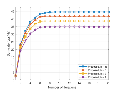
We start with presenting the convergence of the proposed joint BS beamforming and RIS reflection design by plotting the sum-rate versus the number of iterations in Fig. 2. Simulation result illustrates that the proposed algorithm can converge fast and within 15 iterations.

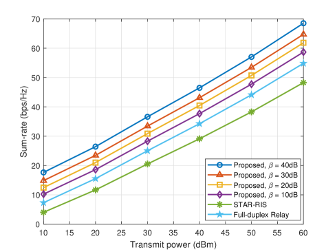
Fig. 3 shows the sum-rate with the proposed dual-functional RIS architecture under different realistic values for the amplification gain β𝛽\beta. For fair comparison, we also include the full-duplex relay equipped with 444 antennas and STAR-RIS proposed in [6] as the benchmark which consumes the same power as the proposed dual-functional RIS aided system. It is noted that the dual-functional RIS with a reasonable amplification gain can result in better performance compared with full-duplex relay since the large-scale RIS has significant beamforming gain. When the amplification gain β𝛽\beta is 40dB, only 30dBm transmit power is required to achieve the same performance, for example, sum-rate is around 37 bps/Hz, while 50dBm transmit power is need when STAR-RIS is deployed.

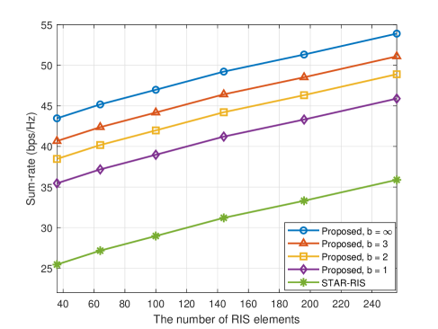
Fig. 4 illustrates the sum-rate versus the number of RIS elements M𝑀M. The same conclusion can be drawn that the proposed dual-functional RIS architecture can substantially enhance the communication quality compared with the conventional passive STAR-RIS scheme. As we can see, only 36 elements adopting 1-bit resolution phase shifters are needed for the proposed dual-functional RIS to achieve the same performance as passive STAR-RIS with 256 elements, which means the dual-functional RIS architecture can improve wireless communication performance without increasing the number of elements.

V Conclusions

In this paper, we introduced a novel reflection and relay dual-functional RIS architecture to overcome the double fading effect and enhance the coverage of downlink MU-MISO systems. Aiming at maximizing the achievable sum-rate, an iterative algorithm based on FP and MM was proposed to design the transmit beamforming and RIS reflection. Simulation results demonstrated the superiority of the introduced dual-functional RIS architecture and the effectiveness of the proposed algorithm.

Refer to caption
Figure 4: Sum-rate versus the number of RIS elements M𝑀M (PTsubscript𝑃TP_{\mathrm{T}} = 40dBm, β𝛽\beta = 30dB).

References

  • [1] Q. Wu and R. Zhang, “Towards smart and reconfigurable environment: Intelligent reflecting surface aided wireless network,” IEEE Commun. Mag., vol. 58, no. 1, pp. 106-112, Jan. 2020.
  • [2] Z. Zhang, L. Dai, X. Chen, C. Liu, F. Yang, R. Schober, and H. V. Poor, “Active RIS vs. passive RIS: Which will prevail in 6G?” Mar. 2021. [Online]. Available: https://arxiv.org/abs/2103.15154
  • [3] E. Björnson, Ö. Özdogan, and E. G. Larsson, “Intelligent reflecting surface versus decode-and-forward: How large surfaces are needed to beat relaying?” IEEE Wireless Commun. Lett., vol. 9, no. 2, pp. 244-248, Oct. 2020.
  • [4] K. Ntontin, M. D. Renzo, and F. Lazarakis, “On the rate and energy efficiency comparison of reconfigurable intelligent surfaces with relays,” in Proc. IEEE Conf. Signal Process. Advances Wireless Commun. (SPAWC Workshop), Atlanta, USA, May 2020, pp. 1-5.
  • [5] C. You, B. Zheng, and R. Zhang, “Channel estimation and passive beamforming for intelligent reflecting surface: Discrete phase shift and progressive refinement,” J. Sel. Areas Commun., vol. 38, no. 11, pp. 2604-2620, Nov. 2020.
  • [6] J. Xu, Y. Liu, X. Mu, and O. A. Dobre, “STAR-RISs: Simultaneous transmistting and reflecting reconfigurable intelligent surfaces,” IEEE Commun. Lett., vol. 25, no. 9, pp. 3134-3138, Sep. 2021.
  • [7] H. Niu, Z. Chu, F. Zhou and Z. Zhu, “Simultaneous transmission and reflection reconfigurable intelligent surface assisted secrecy MISO networks,” IEEE Commun. Lett., to appear.
  • [8] W. Cai, R. Liu, Y . Liu, M. Li, and Q. Liu, “Joint beamforming designs for intelligent omni surface assisted wireless communication systems,” in Proc. IEEE Global Commun. Conf. (GLOBECOM), Madrid, Spain, Dec. 2021.
  • [9] X. Ying, U. Demirhan, and A. Alkhateeb, “Relay aided intelligent reconfigurable surfaces: Achieving the potential without so many antennas,” Jun. 2020. [Online]. Avaliable: https://arxiv.org/abs/2006.06644
  • [10] N. T. Nguyen, Q.-D. Vu, K. Lee, and M. Juntti, “Hybrid relay-reflecting intelligent surface-assisted wireless communication,” Mar. 2021. [Online]. Available: https://arxiv.org/abs/2103.03900
  • [11] N. T. Nguyen, Q.-D. Vu, K. Lee and M. Juntti, “Spectral efficiency optimization for hybrid relay-reflecting intelligent surface,” in IEEE Int. Conf. Commun. Workshops (ICC Workshops), Montreal, Canada, Jun. 2021.
  • [12] R. Long, Y.-C. Liang, Y. Pei and E. G. Larsson, “Active reconfigurable intelligent surface-aided wireless communications,” IEEE Trans. Wireless Commun., vol. 20, no. 8, pp. 4962-4975, Aug. 2021.
  • [13] A. L. Swindlehurst, G. Zhou, R. Liu, C. Pan, and M. Li, “Channel estimation with reconfigurable intelligent surfaces - A general framework,” Oct. 2021. [Online]. Available: https://arxiv.org/abs/2110.00553
  • [14] X. Cheng and Y. He, “Channel modeling and analysis of ULA massive MIMO systems,” in Proc. Int. Conf. Advanced Commun. Tech. (ICACT), Gangwon-do, South Korea, Feb. 2018, pp. 411-416.
  • [15] E. Björnson and L. Sanguinetti, “Power scaling laws and near-field behaviors of massive MIMO and intelligent reflecting surfaces,” IEEE Open J. Commun. Society, vol. 1, pp.1306-1324, Sep. 2020.
  • [16] K. Shen and W. Yu, “Fractional programming for communication systems-Part I: Power control and beamforming,” IEEE Trans. Signal Process., vol. 66, no. 10, pp. 2616-2630, May 2018.
  • [17] K. Shen and W. Yu, “Fractional programming for communication systems-Part II: Uplink scheduling via matching,” IEEE Trans. Signal Process., vol. 66, no. 10, pp. 2631-2644, May 2018.
  • [18] Y. Liu and J. Li, “Linear precoding to optimize throughput, power consumption and energy efficiency in MIMO wireless sensor networks,” IEEE Trans. Commun., vol. 66, no. 5, pp. 2122-2136, May 2018.