A Flexible Exoskeleton for Collision Resilience
Abstract
With inspiration from arthropods’ exoskeletons, we designed a simple, easily manufactured, semi-rigid structure with flexible joints that can passively damp impact energy. This exoskeleton fuses the protective shell to the main robot structure, thereby minimizing its loss in payload capacity. Our design is simple to build and customize using cheap components and consumer-grade 3D printers. Our results show we can build a sub-, autonomous quadcopter with visual navigation that can survive multiple collisions, shows a five-fold increase in the passive energy absorption, that is also suitable for automated battery swapping, and with enough computing power to run deep neural network models. This structure makes for an ideal platform for high-risk activities (such as flying in a cluttered environment or reinforcement learning training) without damage to the hardware or the environment.
I Introduction
When collisions are hard to avoid, the main strategy for Uncrewed Aerial Vehicle (UAV) designs have been the use of protective structures mostly made of materials that are hard themselves. They usually vary from fixed structures [1], to rotating ones [2, 3].
Instead of only a cage, a frame that is capable of absorbing impact energy is another option for collision resilient drones. Despite that, previous works [4, 5] make it very difficult for the UAV to instantly recover because they usually lead to an inevitable fall to the ground as they automatically fold or disconnect the motors. Yet, one significant advantage of not using any special structure to keep propellers from touching obstacles is the increase in payload capability. Nevertheless, unprotected propellers don’t allow UAVs to physically interact with the external world.
Arthropods are an interesting source of inspiration for innovative UAV designs. Cockroaches can transition faster by hitting walls [6]. All arthropods have an exoskeleton, and it has a dual-purpose: it works as support and protective structure. Nevertheless, it is not necessarily fully rigid, allowing bending and compression. For an UAV, such a mixed structure helps increasing the maximum payload and could afford a simpler control system that allows the UAV to physically interact with the environment without damage.
Many regulatory agencies use the as the threshold for the need of special licenses. However, only a few collision resilient designs keep the weight below [7, 8, 5]. It is also rare to find research drones under offering the extra power to run computationally complex software on-board (e.g. object detection using neural network models [9, 10]).
The use of truly exoskeleton-like structure mixing rigid and soft materials in a sub- quadcopter has not been studied or presented yet. Some works like [5] explored flexible frames, but propellers are mostly exposed, you can’t manufacture it without specialized materials or tools, and they lack the ability to fly autonomously without an external system.
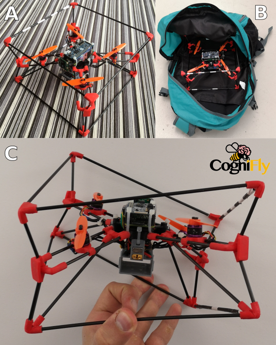
Here we present the CogniFly (Figure 1). It is inpired by arthropods, resulting in an exoskeleton made of carbon fiber rods, connected by 3D printed soft joints. It is designed to protect sensitive components and passively damp impacts. CogniFly’s design depends only on readily available carbon fiber rods and 3D printers. Also, it can run reasonably complex algorithms and custom deep neural networks models despite of its relatively small size and weight, which opens the doors for several potential applications like agriculture, subterranean exploration, drone swarming and many others.
II Materials and methods
II-A Structural design and onboard payload composition
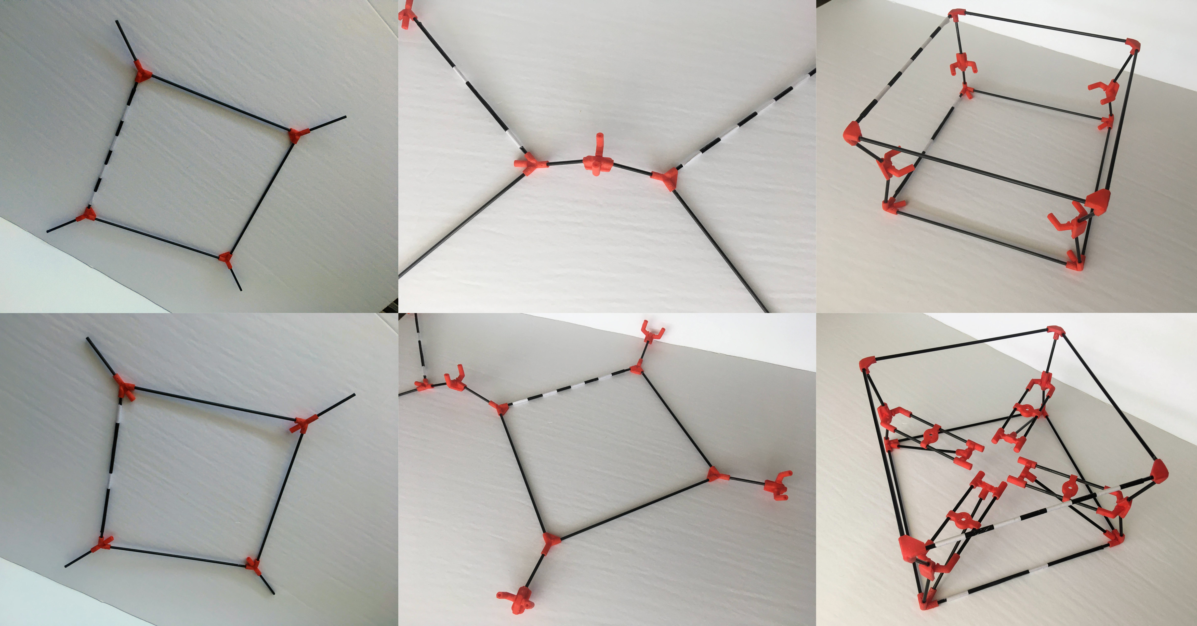
The CogniFly takes inspiration from arthropods’ exoskeletons in that its protective cage is a part of the overall structure. The protective role of the exoskeleton calls for the ability to damp and distribute impact energy, which leads to the use of 3D printed flexible joints (TPU 95A) to connect the carbon fiber rods (Figure 2). This material enables the drone to be generally flexible, as shown in Figure 1-C, which helps dissipating impact energy, while keeping the shape of its central part, allowing operation with a regular flight controller.
CogniFly uses a Raspberry Pi Zero W with a camera module v2, and it runs complex models using Google’s AIY Vision Bonnet (also supporting the Coral USB Accelerator). It features an Optical Flow and Time-of-Flight sensors, thus CogniFly can operate autonomously. Its battery holder and sleeve are designed to enable easy and quick automated extraction and insertion of batteries111More details available at thecognifly.github.io.
II-B Free fall crash landing experiments
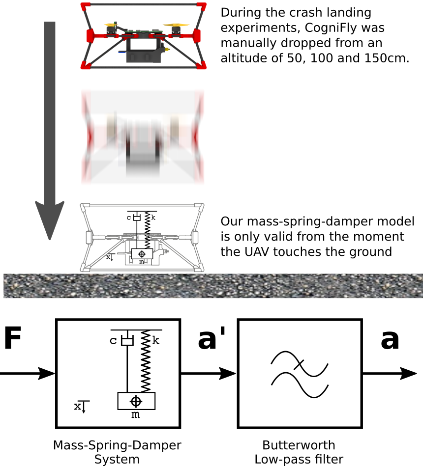
We reckon a vertical free fall to be a critical scenario as we consider payload contact with hard exterior objects, like the ground, has the highest potential of causing damage. Moreover, the battery is located at the bottom part of the drone, and it should not be subjected to extreme mechanical loads. The main criterion we adopt in this regard is the maximum absolute acceleration of the payload in case of a vertical free fall impact (i.e. crash landing), depicted in Figure 3. To test our exoskeleton design, we perform a series of free fall crash landing experiments and record the absolute acceleration using the ADXL377 (3-Axis, 200G, 500Hz) to assess the UAV’s ability to absorb impact energy by comparing between the values recorded from the flexible CogniFly’s frame () and only the rigid central part of the frame made entirely of ABS ().
II-C Mass-spring-damper model
The impact absorbing aspect of the CogniFly for the free fall experiments is modelled as a mass-spring-damper system () where is the mass, is the equivalent damping coefficient of the damper and is the equivalent stiffness of the spring. Moreover, we augment the previous model with a first order butterworth low pass filter () to model the sampling latency.
A loss function is created to estimate the equivalent damping () using the Mean Square Error (MSE) between our model (Figure 3, bottom) and the collected acceleration peak data for all experiments. The value of the equivalent stiffness is obtained through a unidimensional static deformation test.
The mass-spring-damper model allows the estimation of the energy that goes into different parts of the system during impacts (Figure 3). As a simplification, our model can’t take into account the collision between the payload and the ground and it is only valid until . Therefore, in these situations we calculate the energy dissipated by the damper considering the difference between the initial kinetic energy and the kinetic energy when .
III Results
In the following, we present results that show CogniFly’s ability to absorb impacts and how our mass-spring-damper model helps understanding the overall structural behaviour.
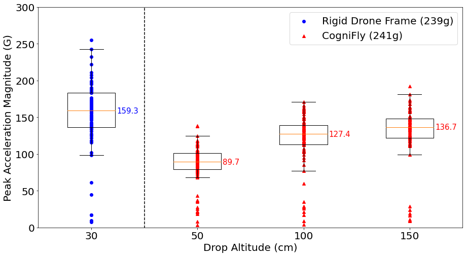
We carry out the free fall experiments for the CogniFly at three different altitudes: . To avoid irreparable damage to the rigid structure used in the comparisons, we limit its free fall to . Figure 4 shows the median of the absolute acceleration peak values for the rigid frame falling from is higher than that of the CogniFly falling from , a five-fold () improvement.
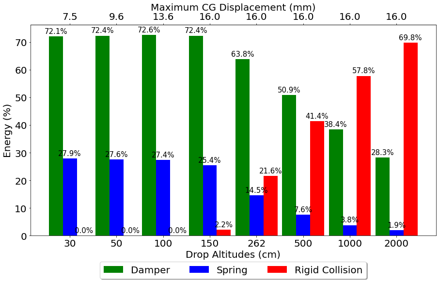
Using the data collected from the experiments (Figure 4), the minimization of the loss and the static measurements resulted in a mass-spring-damper model with coefficients and . Using this model, we predict the distribution of energy stored and dissipated. The results (Figure 5) show a graceful degradation where the energy that will eventually cause a failure (collision) doesn’t increases in steeply and even at 20m (2000cm) more than of the initial potential energy will end up being dissipated (damper) and stored (spring) by the frame according to our model.
For altitudes below , Figure 5 shows that the total kinetic energy is divided between the damper and the spring, while for higher altitudes the amount of energy that goes into rigid collision increases with altitude. Such collision energy can give an indication of how strong the impact between payload and ground is, and this can help deciding how far the operational altitude of the drone can be pushed, had there been a need to go beyond a safe altitude.
As a final test, CogniFly was dropped multiple times from 262cm (the maximum altitude our experimental setup allowed us, literally our ceiling). Although the drone reached a speed at impact of approximately , it didn’t sufferred any damage. Compared to some of the latest works on collision resilience UAVs with equivalent size and weight [8, 4, 11], CogniFly reached a higher speed at impact without damages.
IV Discussion and Conclusions
In this paper, we introduce a new paradigm for collision resilient UAV design inspired by the flexible exoskeleton of arthropods, fusing the protective cage and the main frame in one semi-rigid structure with flexible joints that can withstand high-velocity impacts. Our UAV (Figure 1), weighs under and blends rigid and soft materials giving the final structure the ability to absorb and dissipate impact energy, while still being sufficiently stiff for agile flight. Thanks to its exoskeleton, it is possible to save precious payload capability when compared to a traditional protective cage design.
CogniFly survived multiple collisions at speeds up to while carrying enough computing power to run deep neural network models. Throughout a series of simple crash landing experiments (Figure 3), we show CogniFly withstands up to a five fold increase in the maximum collision energy when compared to a rigid system (3D printed on ABS) of similar weight. Moreover, we employ the experimental data to create a lumped mass-spring-damper model that allows us to extrapolate the results to untested cases while the calculated damping and stiffness can be used in to better understand the role of different materials or configurations.
We designed CogniFly from the ground up for easy manufacturing and it can be built using a very small consumer-grade 3D printer, in addition to inexpensive off-the-shelf parts. The design of the drone itself was restricted by maximum weight (below ) and size (able to fit in a backpack without any disassembly, Figure 1).
Finally, as this is an open source project, all 3D files, software and data will be freely available under The CogniFly Project.
Acknowledgments
References
- [1] Nikhil Khedekar, Frank Mascarich, Christos Papachristos, Tung Dang, and Kostas Alexis. Contact–based navigation path planning for aerial robots. In 2019 International Conference on Robotics and Automation (ICRA), pages 4161–4167. IEEE, 2019.
- [2] Adrien Briod, Przemyslaw Kornatowski, Jean-Christophe Zufferey, and Dario Floreano. A collision-resilient flying robot. Journal of Field Robotics, 31(4):496–509, 2014.
- [3] Carl John Salaan, Kenjiro Tadakuma, Yoshito Okada, Yusuke Sakai, Kazunori Ohno, and Satoshi Tadokoro. Development and experimental validation of aerial vehicle with passive rotating shell on each rotor. IEEE Robotics and Automation Letters, 4(3):2568–2575, 2019.
- [4] Jing Shu and Pakpong Chirarattananon. A quadrotor with an origami-inspired protective mechanism. IEEE Robotics and Automation Letters, 4(4):3820–3827, 2019.
- [5] Stefano Mintchev, Jun Shintake, and Dario Floreano. Bioinspired dual-stiffness origami. Science Robotics, 3(20), 2018.
- [6] Kaushik Jayaram, Jean-Michel Mongeau, Anand Mohapatra, Paul Birkmeyer, Ronald S Fearing, and Robert J Full. Transition by head-on collision: Mechanically mediated manoeuvres in cockroaches and small robots. Journal of the Royal Society Interface, 15(139):20170664, 2018.
- [7] Yash Mulgaonkar, Anurag Makineni, Luis Guerrero-Bonilla, and Vijay Kumar. Robust aerial robot swarms without collision avoidance. IEEE Robotics and Automation Letters, 3(1):596–603, 2017.
- [8] Pooya Sareh, Pisak Chermprayong, Marc Emmanuelli, Haris Nadeem, and Mirko Kovac. Rotorigami: A rotary origami protective system for robotic rotorcraft. Science Robotics, 3(22), 2018.
- [9] Daniele Palossi, Antonio Loquercio, Francesco Conti, Eric Flamand, Davide Scaramuzza, and Luca Benini. A 64-mw dnn-based visual navigation engine for autonomous nano-drones. IEEE Internet of Things Journal, 6(5):8357–8371, 2019.
- [10] Shuo Li, Erik van der Horst, Philipp Duernay, Christophe De Wagter, and Guido CHE de Croon. Visual model-predictive localization for computationally efficient autonomous racing of a 72-g drone. Journal of Field Robotics, 2020.
- [11] J. Zha, X. Wu, J. Kroeger, N. Perez, and M. W. Mueller. A collision-resilient aerial vehicle with icosahedron tensegrity structure. In 2020 IEEE/RSJ International Conference on Intelligent Robots and Systems (IROS), pages 1407–1412, 2020.