Empowering End-users
with Object-aware Processes
Abstract
Business process management systems from various vendors are used by companies around the globe. Most of these systems allow for the full or partial automation of business processes by ensuring that tasks and data are presented to the right person at the right time during process execution. However, almost all established BPMS employ the activity-centric process support paradigm, in which the various forms, i.e., the main way for users to input data into the process, have to be created by hand. Furthermore, traditional activity-centric process management systems are limited in their flexibility as all possible execution variants have to be taken into account by the process modeler. Therefore, large amounts of research have gone into developing alternative process support paradigms, with a large focus on enabling more flexibly executable processes. This article takes one of these paradigms, object-aware process management, and presents the concepts we developed while researching the possibility of bringing the power and flexibility of non-activity-centric process support paradigms to the people that matter: the end-users working with the processes. The contribution of this article are the concepts, ideas, and lessons learned during the development and evaluation of the PHILharmonicFlows runtime user interface, which allows for the generation of an entire user interface, complete with navigation and forms, based on an object-aware process model. This novel approach allows for the generation of entire information systems, complete with data storage, process logic, and now fully functional user interfaces in a fully generic fashion from data-centric object-aware process models. The extensive evaluation performed with the help of an empirical study and a large scale real-world deployment of the process engine and generic user interface, shows that the concepts presented in this paper abstract enough of the challenging conceptual underpinnings of data-centric process management paradigms to make them accessible to end-users when executing processes that require high degrees of flexibility.
keywords:
Object-aware Processes, User-interface Generation1 Introduction
The increasing popularity of process modeling notations, like Business Process Model and Notation (BPMN) are making process documentation commonplace in many companies. Process automation through the use of business process management systems (BPMS), however, is not as commonplace as most BPMS still lack flexibility support, instead favoring rigid processes with high repetitiveness. This is mostly due to the BPMS employing the activity-centric process support paradigm, which can be used to create activities for users along predefined paths determined by a process model. User interaction occurs in the context of human tasks via predefined forms into which users can write data. Adapting these forms for any reason, such as the addition of new fields, of creating variants of the forms for presentation to persons different levels of permission is often a cumbersome and error prone task. In particular, many information systems, whether process-based or not, require individual data elements to not only be held in e.g. a database for persistence, but also handed through various levels of software architecture and interfaces until they are actually displayed for input or output in a form. Finally, while most process management systems offer additional tools like form designers and scripting languages for capturing form logic, these are external to the actual process model itself, and therefore not transparent to the process execution engine. This has numerous drawbacks as the logic and data handled by the form input activities are essentially black boxes to the rest of the process model, which, in turn, means that changes to the process can not automatically change associated forms and vice versa.
Another important aspect to consider is the flexibility of the actual activity execution path defined in the process model. In human-centric processes, in which most activities are form-based, this constitutes the order in which forms are displayed to the various process participants, often based on their roles and process progression. In most process-based systems, deviations to this order are only possible if the process model allows for them, as so-called ad-hoc changes to the process execution are not supported by any major system. More flexible process support paradigms, such as artifact-centric processes [1], case handling [2], adaptive case management [3], or object-aware processes [4] move the focus away from the sequence of activities users have to complete, towards the data of individual business cases. This is essential when wanting to model business cases that are not “rigid” and require large amounts of flexibility while still offering the benefit of steering users through the use of a process model.
While a lot of research has been conducted on modeling and execution of process models for these alternative process support paradigms, little to no research has focused on actually making these paradigms usable by end-users. Even the object-aware paradigm, which was developed specifically for processes with a high degree of user interaction, previously only offered a user interface for “expert” users. This article attempts to close this gap by presenting concepts for a user interface that can adapt to any object-aware process model by generating interface elements from the process model at runtime. The goal was to develop a user interface that automatically adapts to users and the tasks they wish to perform. Additionally, concepts are presented for hiding the complexity of the underlying process model from the end-user. Finally, eliminating the need for a predefined user interface significantly increases productivity and reduces turnaround times for changes to processes [5].
Section 2 discusses the fundamentals of object-aware process management. Section 3, the main contribution of this article, presents fundamental concepts for generating an entire user interface from an object-aware process model at runtime. Section 4 presents our extensive empirical and real-world evaluation of the implementation of our developed concepts, whereas Section 5 examines related work. Finally, Section 6 provides a summary and an outlook on future work.
2 Fundamentals
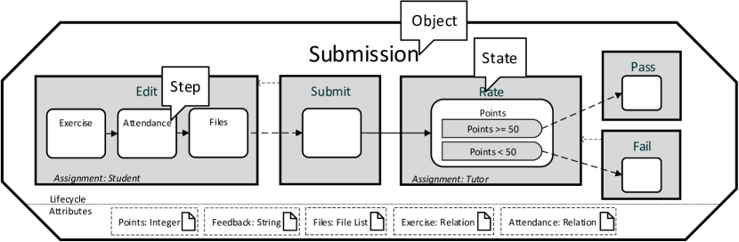
This section provides an overview of the conceptual foundations of object-aware process management, which are crucial for understanding our work. PHILharmonicFlows, the object-aware process management framework we are using as a test-bed for the concepts presented in this article, has been under development at Ulm University [6, 4, 7] for many years. PHILharmonicFlows takes the idea of a data-driven and data-centric process management system, enhancing it with the concept of objects. For each business object present in a real-world business process one such object exists. As can be seen in Fig. 1, an object consists of data, in the form of attributes, and a state-based process model describing the data-driven object lifecycle. We utilize an object-aware process model of the PHoodle (PHILharmonicFlows Moodle) e-learning platform as the running example for explaining the fundamentals of object-aware process management in this article. The example model, when deployed and executed, enables students to download exercise sheets and create submissions for them while attending a university lecture. Furthermore, other students working as tutors may rate their submissions.
Objects and Object Instances
In object-aware process management, an object only describes the structure of its contained data and process logic at design-time and an object instance holds concrete data values and executes the process logic at runtime. This may be compared to the concept of a table and its rows in a relational database, with the table describing the schema of the contained data and the rows containing the actual data values at runtime. We further examine the concept of objects utilizing the example of a Submission object, which attendees of a lecture may instantiate at runtime to hand in exercise or homework submissions in our e-learning platform example.
Attributes and Lifecycle Processes
The attributes of the Submission object (cf. Fig. 1) include Points, Feedback, Files, Exercise, and Attendance. The lifecycle process, in turn, describes the different states (Edit, Submit, Rate, Pass, and Fail), an instance of a Submission object may enter during process execution. Each state contains one or more steps, each referencing exactly one of the object attributes, and enforces that the respective attribute is written at runtime. The steps are connected by transitions, which arrange them in sequence. The state of the object changes when all steps of a state are completed, i.e., after all attributes referenced by the steps have been written. Furthermore, it is possible to assign permissions to attributes, even those that are not referenced by any steps in the lifecycle process, e.g. Feedback. These permissions can be used to permit the reading or writing of attributes not being essential to the execution of a state. Although largely omitted from this article, permissions are essential in providing read access to attributes that were supplied with data at earlier points in the object lifecycle or write access to optional attributes, i.e., those that are not part of the lifecycle process in the form of steps. Finally, alternative and return paths through the lifecycle process are supported in terms of decision steps and backwards transitions. An example of a decision step is given by the Points decision step in the Rate state, which branches the execution to the states Pass or Fail based on the value of the Points attribute. On the other hand, an example of a backwards transition, which allows the lifecycle process to return to an earlier state, can be seen between the Submit and Edit states. To be more precise, this backwards transition allows a Submission to be returned to the Edit state while it is in the Submit state. However, as the model does not contain a backwards transition from state Rate to state Edit, editing the Submission at a later point is impossible.
Lifecycle Process Execution
As PHILharmonicFlows is data-driven, the lifecycle process execution of an instance of the Submission object can be understood as follows: The initial state of a Submission is Edit. Once a Student has entered data for attributes Exercise, Attendance, and Files, the Student may trigger the outgoing transition to the Submit state (cf. Fig. 1, dashed line exiting step Files). This causes the Submission to change its state to Submit, in which it waits until the submission period is over (cf. Paragraph Coordination), after which the Submission automatically transitions to state Rate. As state Rate is assigned to a Tutor, a user with role Tutor must input data for Points. Based on the entered value for Points, the state of the Submission object either changes to Pass or Fail.
Form Generation
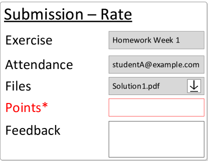
Obviously, this fine-grained approach to modeling the individual parts of a business process increases complexity compared to the activity-centric paradigm, where the minimum granularity of a user action corresponds to one atomic “black box” activity, instead of an individual data attribute. However, as one of the major benefits, the object-aware approach allows for automated form generation at runtime. This is facilitated by the lifecycle process of an object, which dictates the attributes to be filled out before the object may switch to the next state. This information is combined with the attribute read/write permissions, resulting in a personalized and dynamically created form. An example of such a form, derived from the lifecycle process in Fig. 1, is shown in Fig. 2.
The Data Model and Data Model Instances
A single object and its resulting forms only constitute one part of a complete business process in PHILharmonicFlows. To allow for more complex executable business processes, many different objects and users need to be involved [6]. It is noteworthy that users are simply represented by special objects in the object-aware process management concept. The entire set of objects present in a PHILharmonicFlows process is denoted as the data model, an example of which can be seen in Fig. 3. The objects representing users are marked in green, i.e., there are two different types of user objects in the e-learning data model, Employees (e.g. supervisors and staff) and Persons (e.g. students and tutors).
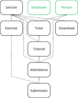
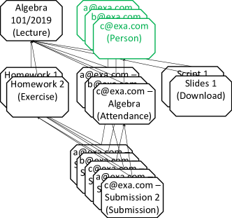
In addition to the objects and users, the data model contains information about the relations existing between them. A relation constitutes a logical association between two objects, e.g., a Submission and an Exercise. At runtime, each of the objects may be instantiated many times as object instances. Note that the lifecycle processes present in the various object instances may be executed concurrently at runtime, thereby improving overall system performance. Furthermore, the relations can also be instantiated at runtime, e.g., between an instance of a Submission and an Exercise, thereby associating the two object instances with each other. The resulting meta information, expressing that the Submission in question belongs to the Exercise, can be used to coordinate the processing of the two object instances with each other at runtime [6]. Fig. 4 shows an example of a data model instance at runtime.
Coordination
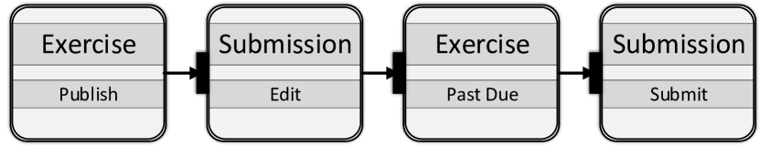
The coordination of the object instances present in a data model instance becomes necessary as business processes usually consist of hundreds or thousands of interacting business objects [8], whose concurrent processing needs to be synchronized at certain states. As object instances publicly advertise their state information, the current state of an object instance (e.g. Edit or Submit) can be utilized as an abstraction for coordinating its processing (i.e., execution) with other object instances corresponding to the same business process through a set of constraints and rules, defined in a separate coordination process [6]. As an example consider a set of constraints stating the following:
-
1.
An Exercise must be in state Publish for Submissions that are related to it to be allowed to progress past state Edit (i.e., to state Submit, cf. Fig. 1).
-
2.
An Exercise must be in state Past Due for Submissions that are related to it to be allowed to progress past state Submit (i.e., to either state Pass or Fail, cf. Fig. 1).
A simplified and abstracted coordination process representing these constraints is shown in Fig. 5.
Implementation Architecture
In our current proof-of-concept prototype, the various higher level conceptual elements of object-aware processes, i.e., objects, relations, and coordination processes, are implemented as microservices. For each object instance, relation instance, or coordination process instance, one microservice instance is created at runtime, turning the implementation, PHILharmonicFlows, into a distributed process management system for object-aware processes. Each microservice only holds data representing the attributes of its object. Furthermore, the microservice only executes the lifecycle process of the object it is assigned to. The only information visible outside the individual microservices is the current “state” of the object, which, in turn, is used by the microservice representing the coordination process to properly coordinate the objects’ interactions with each other using the coordination process model (cf. Fig. 5).
3 Presenting Object-aware Processes to End-Users
After having discussed the fundamental concepts of object-aware processes in Section 2, this section presents the core concepts for making the execution of object-aware processes possible for end-users. Our goal was not only to enable the execution of object-aware processes for expert users (e.g. IT specialists), but also for end-users having no knowledge of the process model, or even the concept of a “process”. Ideally end-users should not even realize that they are interacting with a process management system.
To facilitate this, we developed a number of concepts for generating entire user interfaces, including forms and navigation elements, from processes created with the object-aware process management paradigm. Furthermore, we implemented these concepts into the PHILharmonicFlows engine and created a web-based runtime user interface for large scale testing and verification of the correctness and usability of the concepts. The result is a fully generic user interface that can load any object-aware process and enable user interaction without any additional code. A user interface prototype showing the supervisor view on a lecture from our example data model instance (cf. Fig. 4) is presented in Fig. 6.
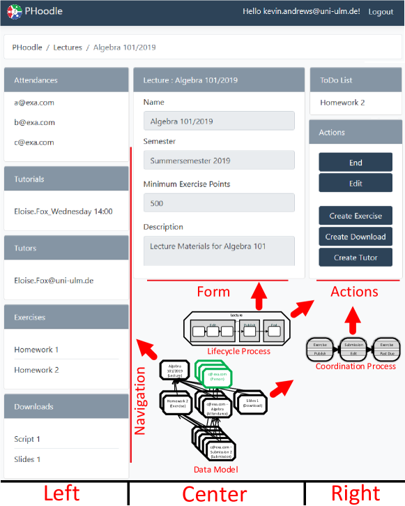
While this is the current version of the user interface, which we are also employing for various studies and further research, keep in mind that the goal of our research is to compress the complexity of data-centric processes into a form that enables end-users to utilize them and not to create the best possible website design. Note that, apart from trivial functions such as “Logout”, not a single string in the user interface shown in Fig. 6 is hard-coded, but instead derived directly from the conceptual process model. Furthermore, no part of the user interface is hard-coded in the process model either, i.e., there are no configuration files attached to the process model determining which elements are placed where in a form.
Examining the provided screenshot closer (cf. Fig. 6) reveals three distinct vertical columns, starting below the breadcrumb-style navigation helper. The left column gives an overview over objects and their respective instances and offers users a way to navigate from object instance to object instance. The center column displays a form for the currently selected object instance. Finally, the right column shows a general to-do list as well as all actions currently available to the user. Note that the user interface is always displayed for one specific user viewing one specific object instance. A different user viewing the same lecture object instance with a different role would see an entirely different page, with different objects, form elements, and actions. As the generation concepts for the content of the three columns are very different, we dedicate the following three sections to one column each, starting with the object instance navigation menu (left column).
3.1 Generating the Navigation Menu
While for very small examples it might be feasible to just display a list of all object instances, perhaps grouped by objects, PHILharmonicFlows supports very large data models with many different types of objects. In this scenario, such a list would quickly cause a lack of overview and confuse users as they constantly see objects not relevant to their current work. Earlier iterations of the PHILharmonicFlows user interface tackled this problem in a naive way by providing filtering tools, allowing users to search for the type and identifier of the object instance they wanted to interact with. However, this filter-based navigation concept was completely replaced when developing the concepts presented in this article. To be more precise, it was simply too cumbersome and required knowledge from end-users about the data model itself in order to “know” which objects they had to interact with, and when.
Instead, the concept for navigating object instances presented in this article utilizes the data model and the therein contained relations, as well as the permission the user has, to only present the most relevant object instances. In the following we illustrate basic concepts, along the data model instance from the example presented in Fig. 4. The entirety of all object instances present in this data model instance is a set of 1 Lecture, 2 Downloads, 3 Persons, 3 Attendances (linking the Persons to the Lecture), 2 Exercises, and 5 Submissions.
First, when deciding which object instances shall be shown in the navigation menu, it must be determined which object instance the user is currently examining. Usually, this is simply the result of the previous navigation command. Next, it must be determined to which object instances the user most likely wants to navigate next. To this end, we employ the relations that exist between the various object instances. As the relations between the objects form a directed acyclic graph at design-time, it is possible to organize the data model into various levels, with the objects on lower levels “belonging” to their respective higher level objects. In particular, the concept only considers instances of objects from lower levels that are directly related to the current object. Fig. 7 highlights the relations from other objects to the Lecture object that constitute direct (i.e., non-transitive) relations.
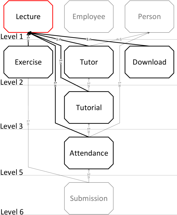
Note that the information on which objects are directly related to the current object can be analyzed statically based on the design-time data model. Moreover, its offers an initial filter for the object instances to be displayed. Furthermore, for an Employee with role Supervisor (i.e., a user having the permissions to view all object instances belonging to an object), this quick graph analysis is sufficient to determine which object instances should be displayed in the navigation menu. For example, this is reflected in the navigation menu of the supervisor view on a lecture (cf. Fig. 6, left column), which was generated based on the analysis of the data model from Fig. 7.
For users with restrictions on the object instances they may view, such as Persons with the Student role, a more sophisticated approach is required. In addition to the static analysis based on the data model, filtering based on the type of object currently being examined (i.e. the context object instance) as well as the permissions and actual relation instances existing at runtime have to be taken into account. For example, a student not having any permissions on the Tutor object should not see any Tutor object instances. This is accomplished by the extensive permission system employed by object-aware process management (cf. [7] for details). Furthermore, and far more important regarding the contribution of this article, it becomes necessary to analyze the relation instances between the object instances at runtime, i.e., a dynamic analysis of the data model instance is required while the navigation menu is being generated. Fig. 8 shows the part of the data model instance that can be seen by the Person a@exa.com after applying basic permission filtering, i.e., after removing all object instances his role, i.e., Student, does not have permissions to view.
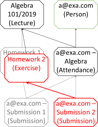
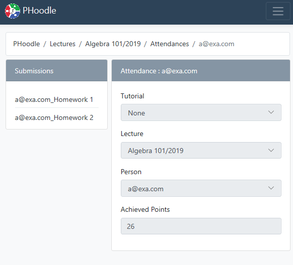
Furthermore, note that Exercise Homework 2 is the context object instance for which the dynamic filtering should occur. The context object instance determines the source parameter for an algorithm that filters to lower level object instances with an existing relation instance to the context object instance. In the example from Fig. 8, this filters the lower level object Submission to the only instance having a relation instance to the context object instance Homework 2, i.e., Submission 2. In our approach, this analysis results in the user interface shown in Fig. 9 being generated on the fly.

Note that the navigation only consists of one possible object, as for Homework 2, Submission 2 is the only lower level object instance related to Exercise Homework 2, which is the current context object in Fig. 9. Conversely, if the user did not navigate to Homework 2, but instead to, for example, his own Attendance object instance for Lecture Algebra, the situation shown in Fig. 10 would occur.
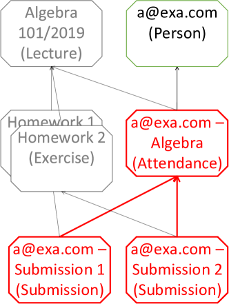
Note that in Fig. 10 the Attendance object a@exa.com-Algebra is the context object instance of the filtering operation which is used to generate the navigation menu. In consequence, the lower level Submission object is filtered to those instances that have a direct relation to the context object instance, i.e., Submission 1 and Submission 2. As this does no longer filter by Exercise the resulting user interface generated during the view creation shows navigation options for the Submissions of both Exercises (cf. Fig. 11).
While these examples have been fairly limited in scope, the concept for generating the navigation menu from the relations of the current context object instance, i.e., the object the user wishes to interact with or show an input form for, works very well, even for large scale data model instances. However, corner cases, in which a very large number of object instances are related to the context object instance and where the user also has permissions allowing access to all of them, do exist. These can be handled in a traditional fashion, e.g., with a simple text-based filter on the navigation element that is generated for the object in question, allowing quick filtering via the label of the individual object instances.
3.2 Generating the Forms
After completing the navigation column, the form for interacting with an object instance is generated. Automated form generation has been a goal of the object-aware process management paradigm from early on. Most lifecycle-based process management approaches support form generation by analyzing the lifecycles present in the process model. However, object-aware process management goes a step further by incorporating a sophisticated permission system as well [7]. In particular, the permission system implemented in the PHILharmonicFlows engine allows for the definition of permissions based current attribute values of on an object instance, as well as roles and permissions which are dynamically evaluated based on the relations that exist between objects at runtime.
The combination of the information gathered from the lifecycle process of an object instance and the permissions the current user has on the various attributes present in the current context object instance, can be utilized for fine-grained form generation. On one hand, the steps of the lifecycle process offer information on the mandatory form fields the user has to provide values for in order to advance the object instance to the next state. On the other, permissions are utilized to allow reading or writing form fields for optional attributes, which are not mandatory as part of the lifecycle execution or have already been written beforehand. An example of such a form, in particular a screenshot of the form concepted in Fig. 2 and derived from the Submission object presented in Fig. 1, is shown in Fig. 12.
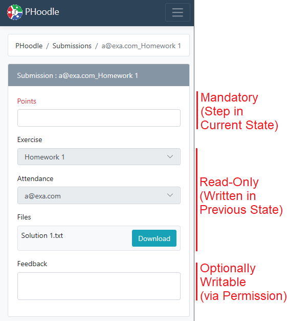
Note that there is no navigation column on the left as a Submission is on the lowest level of objects (cf. Fig. 7) and there are no lower level object instances attached to it which could be navigated to. Furthermore, there is no action column on the right as there are no context actions for the current object instance because the lifecycle process of Submission objects requires the Points attribute to be written (i.e. provided a value) before lifecycle process execution may continue to the next state (cf. Fig. 1).
3.3 Generating To-do Lists and Context Actions
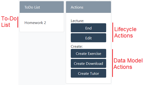
This section explains the concepts behind the generation of the to-do list and its corresponding actions available in the context of an object instance. Fig. 13 is a rearranged crop of Fig. 6, reiterating the parts of the user interface relevant for the following sections.
3.3.1 To-do List
The to-do list is actually fairly simple, as it is directly derived from the role assignment of the current state of an object instance. As discussed in Section 2, each object lifecycle contains multiple states that may be traversed by corresponding object instances during lifecycle execution. Each of these states may have assigned roles, meaning that users possessing these roles are supposed to advance the objects from the state in question to the next state.
Regarding the to-do list element of the user interface, we combine this assignment information with a relaxed version of the algorithm for generating the navigation menu, which also takes into account the object instances transitively related to the current context object instance. This allows the user interface to display any lower level object instance of the current context object instance in the to-do list, as long as it is assigned to one of the roles the current user has. For example the to-do list of an Employee with role Supervisor, viewing a Lecture that has relations to instances of the Exercise object, would show all Exercise object instances which are still in state Edit, as is the case for Homework 2 in Fig. 13. In our concept evaluation study, the to-do list has proven to be an essential tool in providing actual process support to users without knowledge of the data model, guiding them to the next object instance with pending work.
The “action” elements of the user interface are the actions available in the context of an object instance. These can be categorized into lifecycle actions and data model actions.
3.3.2 Lifecycle Actions
The lifecycle actions available in the context of an object instance correspond to the actions dealing with state traversal. This includes advancing an object instance to the next state with a transition, or returning to a previous state with a backwards transition (cf. Section 2). In particular, early concepts of the PHILharmonicFlows user interface relied on showing a model of the lifecycle process to users, allowing them to click on transitions to trigger state changes in a graph-based view. However, the idea was discarded as it is not feasible to require users to have knowledge of process models. Instead, the permission system was extended to support transition permissions, thereby allowing the user interface to present state traversal actions only to those users having the permission to advance to a successor or predecessor state using a transition. In consequence, there are lifecycle actions available to an Employee with the Supervisor role in the context of a Lecture, namely End and Edit (cf. Fig. 13). A user logged in as a Person with the Student or Tutor role, however, would not see these actions as the process model for the e-learning example does not grant the necessary permissions.
On a side note, the labeling of actions End and Edit is automatically derived from the lifecycle process model for the Lecture object, which was omitted from the article, as it only contains three states labeled Edit, Publish, and End. As the context object for the user interface shown in Fig. 13 corresponds to a Lecture in the Publish state (cf. also Fig. 6), the transition from Publish to End and the backwards transition from Publish to Edit cause the generation of the corresponding buttons as actions in the user interface.
3.3.3 Data Model Actions
A fundamental concept added to object-aware process management consists of the data model actions offered to users in the PHILharmonicFlows user interface. In particular, while a large part of this article deals with the object instances and relation instances comprising a data model instance, it has not been discussed how these relation instances are created at runtime. Moreover, while concepts such as relations between data as well as treating data as first-class citizens in a process model, exist in many process support paradigms, the complexity these concepts bring with them is largely ignored in existing works. Note that for any process support paradigm to be usable in the real world, the complexity of creating large data structures has to be hidden from users.
To this end, we developed multiple extensions to the object-aware process support paradigm. As a first extension, we introduced the ability to define relation attributes, i.e., object attributes that hold a related object instance as their value. Similarly to restricting regular attributes to common data types, such as String or Integer, relation attributes are typed by the related object at design-time. The Submission object shown in Fig. 1, for example, contains two relation attributes that are typed to accept instances of objects Exercise and Attendance, respectively. Their representation as a drop down selector in the user interface can be seen in Fig 12 (albeit in their read-only state).
In particular, this user interface element allows end-users to create relations from one object instance to another simply by selecting its name from a drop down list at runtime is a large step forward. Moreover, allowing for the creation of relations to be, effectively, forced as part of the object lifecycle removes ambiguities concerning when and how objects must be related to each other. This allows process modelers to capture rules such as “a submission must always belong to exactly one exercise and one attendee” by simply forcing users to set the corresponding relation attributes at runtime in the first state of the Submission lifecycle process. However, it is still cumbersome to manually attach each newly created object instance to the object instances it must be related to. Additionally, one must explain the concept of relations to users, which is impractical in real-world scenarios.
To alleviate these issues, we developed the CORE (Create Object Relations Efficiently) algorithm (cf. Alg. 1). It takes information present in an object-aware data model and combines it with the newly added concept of relation attributes, thereby enabling fully automatic relation creation when objects are instantiated by users. To aid in understanding the CORE algorithm, Fig. 14 gives an example of a typical situation in which the algorithm may be applied.

Recalling that instances of the Person object are always related to a Lecture via an Attendance (enabling a user to attend multiple lectures), it becomes obvious that Submissions for an Exercise must always be related to (a) the Exercise and (b) the Attendance corresponding to the Person and Lecture. However, as the goal is to hide all this complexity from users, instantiating a Submission creates these relations automatically. To facilitate this, the CORE algorithm (cf. Alg. 1) receives three pieces of information from the user interface: the user currently logged in (Person a@exa.com), the context object instance, i.e., the object instance currently displayed in the user interface (Exercise Algebra Homework 1), and the object the user wants to instantiate (Submission).
When executing, the algorithm first creates an instance of the requested object. Then, the algorithm loops over all relation attributes referenced by steps in the first state of the lifecycle of the new Submission object instance (cf. Alg. 1, Lines 2-3). When it encounters a relation attribute typed to the context object (Exercise), it creates a relation between the new Submission and the Homework 1 context object instance (cf. Alg. 1, Lines 5-8). Furthermore, when it finds relation attributes typed to other objects, e.g. Attendance, it searches for instances of that object which are related a) to the user object instance (Person a@exa.com) and b) to the context object instance (Exercise Algebra Homework 1). This is accomplished directly on the data model instance graph by intersecting common higher level object instances of a candidate object instance and the context object instance.
Regarding the example from Fig. 14, the algorithm would compile a list of all lower level Attendance objects of Person a@exa.com, i.e., Attendance a@exa.com - Physics and Attendance a@exa.com - Algebra. This list would then be filtered to solely include object instances having common higher level instances with the context object instance. As the only higher level object of the context object instance is Lecture Algebra, and only the Attendance a@exa.com - Algebra shares this common higher level object instance, the Algebra Attendance is selected as the target of a new relation, satisfying the Attendance attribute step in the lifecycle of the new Submission object instance (cf. Fig. 1) and completing the CORE algorithm. In consequence, as the algorithm runs during the instantiation of an object instance, the single click by a user to create e.g. a Submission, instantiates the object and two relations instantly, completely hiding the complexity of the relation concept from the user.
4 Evaluation
In order to study whether the presented user interface concepts make object-aware processes usable in the real world, we conducted two distinct evaluations: an empirical usability study utilizing multiple scientific methods (cf. Section 4.1), and a large scale real-world deployment (cf. Section 4.2) of the PHoodle e-learning platform process model.
4.1 Empirical User Experience Study
This evaluation is based on a study conducted with n=70 subjects in which multiple scenarios with various tasks had to be completed using the PHoodle data model running on the PHILharmonicFlows process engine. Interaction with the process engine was enabled by means of the fully generic user interface prototype presented in this article. The study utilized various established scientific methods for quantifying usability and user experience, namely the After Scenario Questionnaire (ASQ), the User Experience Questionnaire (UEQ), and a questionnaire according to ISO norm 9241/110. The decision to employ all three methods simultaneously was made to ensure that as much data as possible was gathered, as each method focuses on slightly different aspects of usability.
4.1.1 Subject Structure
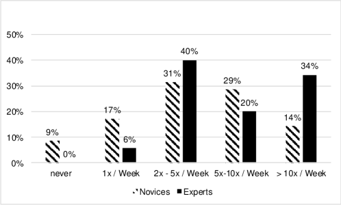
The subjects participating in the study were divided into two groups, consisting of 35 subjects each. The two groups, henceforth called “novices” and “experts”, consist of employees and students of Ulm University. The first group, the “novices” consists of 35 persons who had never worked with PHILharmonicFlows or the PHoodle process model in any capacity. They knew nothing about the theoretical concepts, the user interface implementation, the structure of the data model or therein contained objects. While most of the novices had used other e-learning systems or process management software prior to the study, the novices had no experience or help in using PHILharmonicFlows or the PHoodle process model. Note that almost 10% of novice participants had never used an e-learning system before (cf. Fig. 15).
The “expert” group on the other hand consists of 35 students who had been using PHoodle for two months prior to the study. They had used PHoodle to submit homework and exercise sheets every week over the course of these two months, i.e., each expert had completed at least eight exercise submissions at the time the study was conducted. Furthermore, they were given information on the usage of the PHILharmonicFlows user-interface, as well as some background information on the underlying concepts. Finally, the expert group also had a very high percentage of subjects with very extensive and regular e-learning experience, with 34% percent of subjects reporting usage of over 10 times per week and 94% reporting at least two uses per week (cf. Fig. 15).
4.1.2 Scenarios
Both groups, i.e., novices and experts, were asked to complete the same five scenarios over the course of the study. The scenarios were conducted on a demonstration system running the current PHILharmonicFlows engine and hosting a web version of the user interface prototype presented in this article. The data model was identical to the one used in our real-world deployment and coincides with the data model presented in the fundamentals (cf. Section 2). The data model instance, however, was decoupled from the live data and reset to a predefined state of object instances after each subject to ensure that the actions of one subject could not influence the results of another. The following paragraphs give a short overview over the five scenarios.
Scenario 1 (Registration)
The subjects are asked to register in the PHoodle user-interface with a special e-mail address containing their assigned subject-specific code, allowing them to be tracked across scenarios and correlate their system actions with their questionnaire answers. The registration is, from a user perspective, a very simple task. Accounts are unlocked without e-mail confirmation for purposes of the study.
In the PHILharmonicFlows engine, this action causes the creation of an instance of the Person user object. Furthermore, the e-mail address the subject entered is set as an attribute value of the new object instance. This logic is, however, hidden entirely from the subjects. From their perspective, the registration is identical to any other typical information system, as can be seen in Fig. 16.

Scenario 2 (Attending a Lecture)
After completing Scenario 1, the subjects have a new account in a data model instance prepopulated with object instances for the scenarios. In Scenario 2, they are asked to log in to their new account, select the lecture and “attend” the lecture. Again, this seems like a very simple and familiar task to the subjects, even in this fully generic user interface. After logging in, as long as no Lecture object instance has been selected, the navigation menu shows an overview over all top level objects that the current Person, i.e., the subject, is allowed to read.
Once navigation to a lecture has occurred, the PHILharmonicFlows engine creates a button for the to-do item Create Attendance using to the concepts presented in Section 3.3 (cf. Fig. 17). As the user object instance that was created in Scenario 1 has no other permissions for the lecture, except the creation of an attendance, no other actions are offered by the user interface until this step is completed. To hide the complexity of the creation of the Attendance object instance and as the relation instances between the Attendance, the Lecture, and the Person, the PHILharmonicFlows engine uses the CORE algorithm (cf. Algorithm 1) presented in Section 3.3.3.

Scenario 3 (Checking assigned Tutorial)
After completing Scenario 2, the subjects are asked to log out and log back in to the system, to simulate the passing of time between attending a lecture and having a tutorial assigned by a supervisor. While the subject is logged out, the system automatically assigns (hard-coded for the study) the subject to a tutorial by creating the necessary relations between the Attendance object instance and one of the preexisting Tutorial object instances. According to the principles of object-aware process management, this new relation path between the Person object instance representing the subject and the Tutorial object instance he is assigned to immediately allows the PHILharmonicFlows process engine to resolve new permissions for the subject. From the perspective of the subject, the task of Scenario 3, to check which tutorial he was assigned to, is therefore simple.
As the user interface only presents subjects with navigation options to objects that they have permission to read, they must merely navigate to the Lecture they selected in Scenario 2 and are immediately presented with a new navigation option to their assigned tutorial. Clicking the navigation link shows the form for the Tutorial object instance, which includes attribute values that contain relevant details about the Tutorial, such as the Tutor and the concrete time slot in which the tutorial takes place (cf. Fig. 18).

Scenario 4 (Creating an Exercise Sheet Submission)
After the subject completes Scenario 3, the system generates an example exercise sheet and the subject is asked to download the exercise sheet and complete the task it describes. The task itself is merely creating a file with a certain name and uploading it as part of the solution submission for the exercise sheet. The subjects must first find the Exercise object instance they are supposed to create a Submission for. However, with the help of the To-Do list (or the navigation menu), this task is fairly simple. Upon selecting the correct object instance, the form for the Exercise object instance is shown, with the option to download the PDF file containing the task details (cf. Fig. 19).
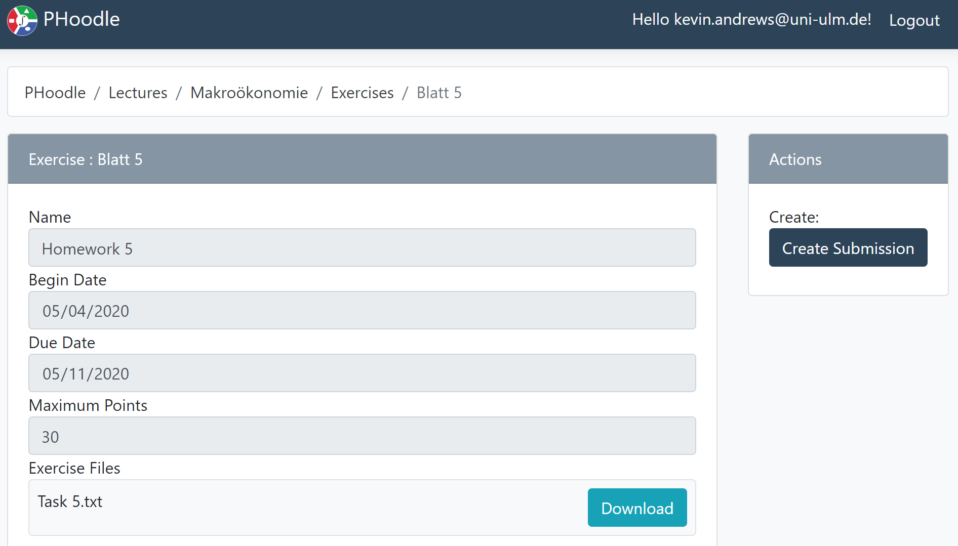
While drawing the form, the PHILharmonicFlows process engine also evaluates the permissions of the subject and generates the button for the Create Submission action, which the subject must press to create a new Submission object instance and (according to the CORE algorithm) also the relation instances to the correct Attendance and Exercise object instances automatically. Finally, while viewing the form for the new Submission object instance, the lifecycle process for the Submission allows the user interface to generate a form with the correct guiding markings, indicating the attribute value (in this case the “solution” file) the subject must supply to be able to submit the submission. Supplying the Solution attribute with a value causes an advancement in the lifecycle process for the object instance that the form is displaying (cf. Fig. 1). As soon as the process engine registers the updated attribute value, the user interface adapts and displays the Submit action, allowing the subject to advance the lifecycle to the next state, thereby completing the submission.
Scenario 5 (Checking achieved Points)
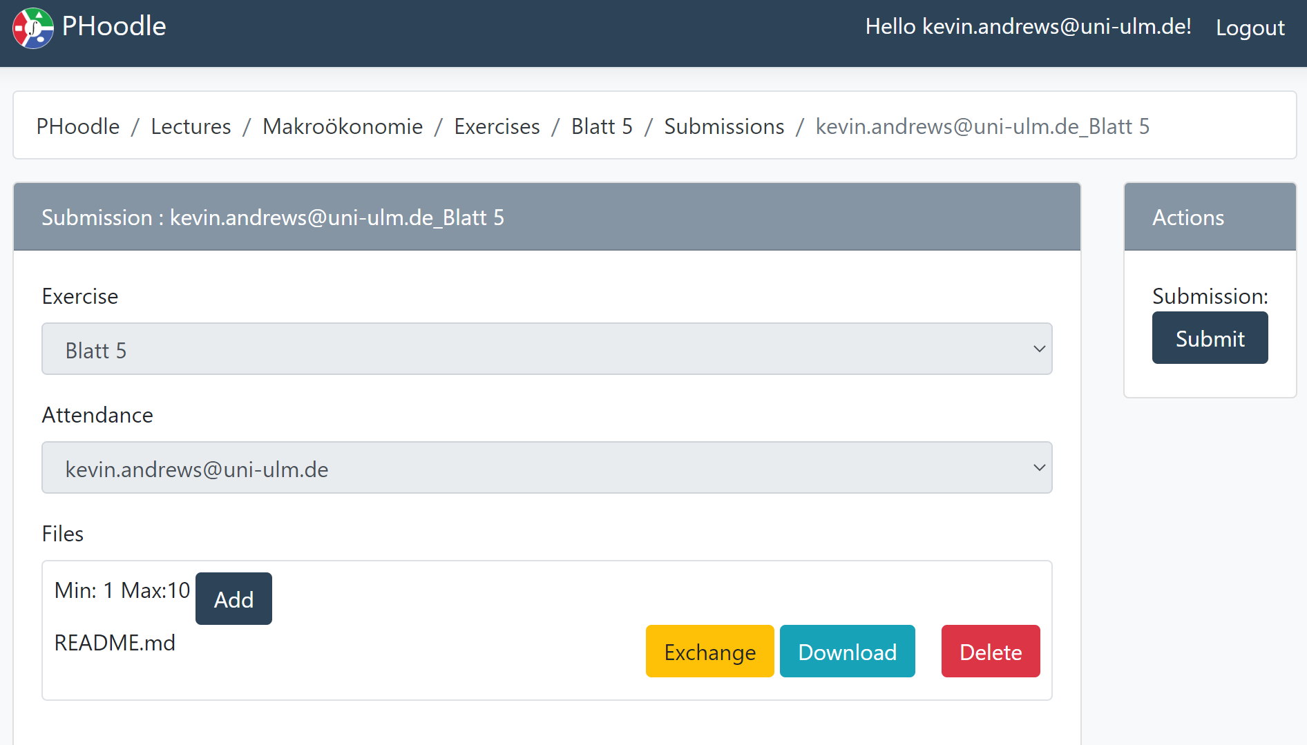
The final scenario involves asking the subjects to check the number of points the received as a rating for their submission. In the break between Scenarios 4 and 5 the system is hard-coded to assign a random rating to the submission, simulating the actions of a tutor. The difficulty in this scenario is that Submissions are attached either to Exercises or Attendances, but not to the Lecture itself. In consequence, in contrast to the other scenarios, where navigation was merely selecting the Lecture and then finding the object instance in the navigation bar, Scenario 5 involves a multi-level navigation. Furthermore, as checking the achieved points is not mandatory, as it is not part of the lifecycle process of a Submission, no to-do item is generated for this scenario. Therefore, the subjects must select either their Attendance object instance, which shows all their submissions, or the correct Exercise object instance, which shows all submissions attached to the exercise, filtered by their permissions. This corresponds to the examples of object content navigation given in Section 3.1, i.e., Fig. 8 and Fig. 10. Once one of the navigation paths is selected by navigating to the Attendance or the Exercise, the Submission object instance created in Scenario 4 can be navigated to, allowing the user interface to display the corresponding form. The form, which still shows the same lifecycle process as in Scenario 2, is presented with additional information, including the required Points attribute. This is due to the fact that the subjects have different permissions in Scenario 5, as the Submission object instance was transitioned to the Pass state during the intermission between Scenarios 4 and 5 by the tutor. The resulting form can be seen in Fig. 21.

4.1.3 Study Goals
The goal of this study was to evaluate the usability of the generic user-interface of PHILharmonicFlows. In particular, we wanted to gauge if we had succeeded in abstracting the inherent complexity of object-aware process management away from the user interface part of the process management system. Furthermore, as this particular approach to user interface generation, i.e., based on a data-centric process model, is novel, we wanted to evaluate whether users could understand and interact with a completely generic user interface. In this context, note that the user interface prototype we evaluated does not contain a single line of code which is specific to the PHoodle process model. All labels, navigation structure, actions, etc. are derived from the process model itself.
The only information we provide to the user interface is an internal data model instance identifier that allows the user interface to request the correct data model instance on startup. Keeping this in mind, one of the main goals of the evaluation was to determine whether the concepts we developed for generating a user interface from the process model (cf. Section 3) were enough to guide a novice user through the various tasks set forth by the scenarios. Furthermore, by including the group of experts, we were able to measure whether a learning curve was necessary to really master the user interface. The hypothesis was, that if the novices took significantly longer than the experts to complete the scenarios or required significantly higher mental effort, the generated PHoodle user interface must have deficits preventing novice users from knowing where in the user interface to complete necessary actions.
4.1.4 After Scenario Questionnaire (ASQ) Results
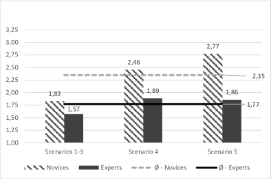
Upon completion of the more complex Scenarios 3, 4, and 5, subjects were asked to fill out an After Scenario Questionnaire (ASQ). The ASQ is an established tool for psychometric evaluation in computer usability studies [9]. While the ASQ only has a few carefully selected questions, they are repeatedly answered by subjects after each scenario they complete. This immediate evaluation allows for the fine-grained evaluation of the experience subjects had in a scenario. The questions posed in our study allow for the evaluation of three distinct metrics: perceived mental effort, perceived efficiency, and perceived effectiveness. While the answers to the ASQ are given on a seven-point Likert scale, the result charts shown in Fig. 22 are clipped to maximum value of 3.25 to save space. This was possible as none of the average results of the ASQ was above 3.23. The Likert scales are structured so that lower values are “better” in terms of usability.
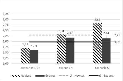

The charts in Fig. 22 allow us to extract some basic observations:
-
1.
The average ASQ results across all 70 subjects and scenarios for the dimensions Mental Effort , Efficiency , and Effectiveness are all around 2. As the results could range from values 1 (extremely low/efficient/effective) to 7 (extremely high/inefficient/ineffective) on the Likert scale, indicating that subjects, on average, considered themselves to have required “very low” mental effort, to be “very effective”, and “very efficient”. This, in itself, can be considered a success from usability perspective, considering that users were interacting with a user interface generated from a process model.
-
2.
In Scenario 5, experts perceived themselves as requiring less mental effort, being more efficient, and only slightly less effective than in Scenario 4. The novices, on the other hand, perceived themselves as requiring significantly more mental effort, and being significantly less efficient and effective in Scenario 5, compared to Scenario 4. This does indicate that there is a learning curve in Scenario 5, with some novice subjects finding it harder to find their submissions due to the multi-step navigation over the exercise object. However, as the experts did not rate Scenario 5 any worse than Scenario 4, one can conclude that the multi-step navigation only poses a issue for first-time novice users. Clearly, this also depends on the data-model being structured in way in which navigation makes sense for users.
-
3.
On average, experts perceived themselves as requiring less mental effort, being more efficient, and more effective across all scenarios than the novices did.
-
4.
When correlating the previous observation with the system logs, however, it is interesting to note that the expert subjects actually took longer on average to complete all five scenarios. As can be seen in Fig. 23, which shows the times the individual subjects needed to complete all scenarios, the average time that the expert subjects needed was almost 15 minutes, while the novice subjects needed an average of nearly 13 minutes. However, considering the individual times and averages, the difference is not significant from a statistical perspective. This is an indicator that the generic user interface is, even while being fully generic, well fitted to its task of guiding users along their interactions with the process model. In particular, as shown by these numbers, first-time novice users have no significant disadvantage in time it takes them to complete the tasks set forth by the scenarios, as the user interface guides them along the same paths that expert users take after weeks of use.
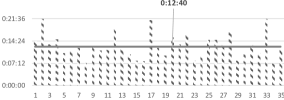
(a) Individual Novices 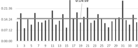
(b) Individual Experts Figure 23: Time Taken to Complete all Scenarios
4.1.5 ISO-Norm 9241/110 Results
The International Organization for Standardization norm 9241/110 [10] concerns the ergonomics of interactive systems and helps identify usability problems. The norm includes a standardized questionnaire which was presented to subjects during our evaluation study. In contrast to the ASQ, the ISO 9241/110 questionnaire was only presented once to subjects, after completion of all scenarios. In consequence, there is only one set of results which does not differentiate between the various scenarios.
Of the seven so-called “aspects” examined by the ISO 9241/110 questionnaire (Suitability for the Task, Self-Descriptiveness, Suitability for Learning, Controllability, Conformance with User Expectations, Error Tolerance, and Suitability for Individualization) only six were examined, as Suitability for Individualization was not applicable because the user interface offers no related options. For each aspect, a series of questions, 16 in total, were answered by subjects. The answers were given on a seven-point Likert scale, as required by the norm. The evaluation of an ISO 9241/110 questionnaire is also standardized by the norm, resulting in the chart shown in Fig. 24. All results are normalized to the range [-3, +3], with the norm considering aspects that are rated at least +1 to be “good”. Therefore, software with at least a +1 rating in all aspects is considered to have good usability according to ISO 9241/110.
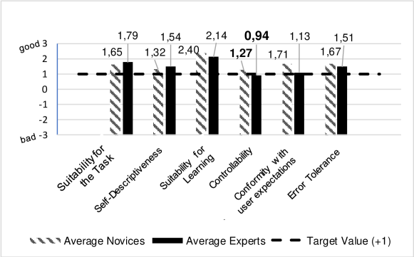
Examining Fig. 24 shows that the generic PHILharmonicFlows user interface hits the target value of +1 across the board when considering the average ratings across novices and experts. However, while the average rating for the Controllability aspect is , the experts rated the aspect below the target value, at 0.94 (cf. bold values in Fig. 24). The Controllability aspect, which rates whether users thought that they “felt in control while working with the software”, is, obviously, a problematic one for any process management system. While novice users might be thankful for the guidance they receive when following the execution path predefined in the process model, experts may feel that their choices are limited by these boundaries. The experts rating this aspect just shy of “good” in the study shows that the problem of perceived lack of control for expert users does also exist in object-aware processes. However, it is not nearly as pronounced as it is in activity-centric process management, where the exact order of all activities is predefined.
The most important aspects for this evaluation are the ratings for the aspects Suitability for the Task and Self-Descriptiveness. They rate whether users thought that “the software supported them in completing their tasks” and “the software was easily understandable and self-explanatory”, respectively. According to Fig. 24, both aspects were rated well above the target value of +1, by novices and experts alike. We consider a good rating in these aspects paramount to the user experience and, therefore, also acceptance of a generic user interface created using a certain approach, such as object-aware process management. Having achieved these results with a prototype shows the viability of the object-aware process management approach for generating user interfaces.
4.1.6 User Experience Questionnaire (UEQ) Results
The final questionnaire presented to subjects was the User Experience Questionnaire (UEQ) [11]. The UEQ is similar to the ISO 9241/110 questionnaire, with seven-point Likert ratings for questions across six so-called “dimensions”. However, the UEQ aims at gathering a quicker, simpler, and more straightforward notion of the experience users have with a piece of software. The study evaluated three of the six UEQ dimensions, i.e., Perspicuity, Efficiency, and Dependability, as the other three, i.e., Attractiveness, Stimulation, and Novelty, where not were not goals of the work presented in this article. Similarly to the ISO 9241/110, the UEQ suggests a target value for each dimension, which is fixed at 0.8, meaning that values over 0.8 constitute a “good” user experience. The results for the examined dimensions are shown in Fig. 25.
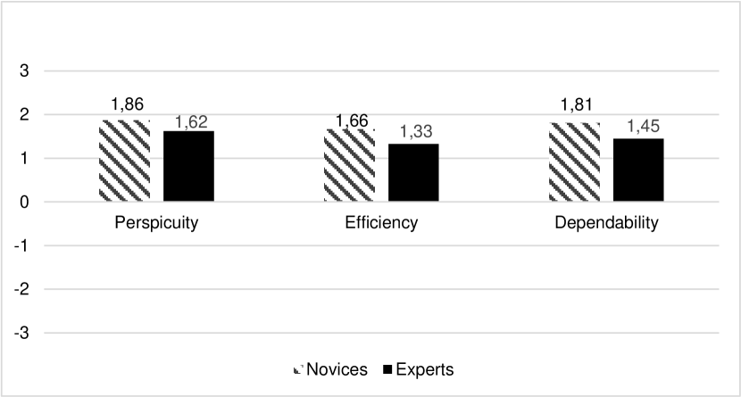
Clearly, the results across all dimensions are well above 0.8, with Perspicuity being rated the highest across novices and experts alike. As Perspicuity basically describes how “easy to grasp” something is, it is no surprise to see this dimension rated highly, as the corresponding aspect in the ISO 9241/110 results, i.e. Suitability for Learning was also the highest rated (cf. Fig. 24). The UEQ however, does also uncover one of the shortcoming of generic user interfaces, and our approach in particular. It becomes obvious when examining the UEQ dimension Efficiency closer, that the lowest rated individual item is how “pragmatic” the user interface is (cf. Fig. 26).

We examined this result item closer, as it was the only one below the threshold of 0.8 for both experts and novices. When correlating the UEQ results with those of the ASQ (cf. Section 4.1.4) and the textual comments made by subjects it becomes clear that the multi-level navigation between related objects, which was necessary to complete Scenario 5, was perceived as less pragmatic than other elements of the user interface. While it is a simple concept from a user perspective and subjects dealt with it efficiently, many subjects wanted to know why the navigation to individual submissions had not been placed on the same level as exercises and tutorials. While it is necessary from a data model perspective to have Submission as a lower level object attached to Exercise for various conceptual reasons (cf. Section 2), this is, naturally, completely unclear to users who just want to know why they cant navigate directly to their submissions when viewing the details of a lecture in their e-learning system.
This is a limitation of our approach to generic user interfaces, as we, by design, do not offer any configuration options for the user interface that are not part of the process model, as this would erode a core aspect of our approach. In particular, adding a bunch of necessary UI configuration on top of the process model would defeat the purpose of having a fully generically generated user interface, as it would then no longer be fully generic.
4.2 Real-World Deployment Measurements
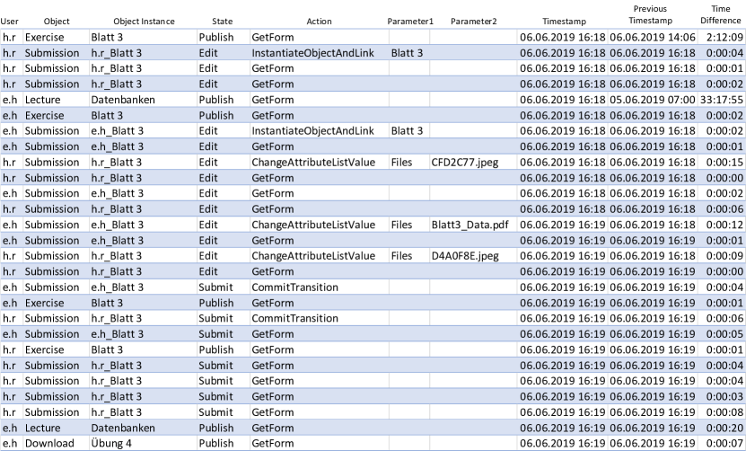
This evaluation is based on a full-scale deployment of the PHoodle data model in the PHILharmonicFlows engine at Ulm University in the summer semester of 2019. The PHoodle deployment111Feel free to log in to the live instance at https://phoodle.dbis.info Username: edoc.demo@uni-ulm.de Password: edoc.demo replaced the established Moodle e-learning platform over an entire semester (exactly 100 days) for hundreds of students. We were able to parse and extract information from nearly 70,000 PHILharmonicFlows process engine log entries which were cleaned and aggregated to a log containing 39,890 interactions. To be precise, each entry in this interaction log is exactly one click or action by a real student, tutor, or supervisor. The log entries we removed from the initial ~70,000 were system debugging information and related log entries we had to create to ensure we could react to problems in the live system if any arose. A sample of some of the columns in the the raw log output we gathered for analysis is shown in Fig. 27.
Note that there are a large number of columns missing, as all labels shown in Fig. 27, such as the names of users, objects, attributes, etc. are actually logged as 64bit integer reference values internally. These reference id columns are then supplemented by a “pretty” string-based form for manual log examination in Excel, which is what is displayed in Fig. 27. Furthermore, all user names and file names etc. were redacted to comply with the GDPR.
We are able to further aggregate this data using common techniques such as pivot tables and lookup formulas, providing us with some useful metrics which show the extent to which the process was utilized in our real-world deployment. We provide some of these to give the reader a sense of scale of our deployment in Table 1.
| Object | Amount | |||
|---|---|---|---|---|
| Instances | Amount | |||
| Interactions | Average | |||
| Interactions | ||||
| per Instance | Max | |||
| Interactions | ||||
| per Day | ||||
| Attendance | 137 | 3233 | 23.6 | 583 |
| Download | 14 | 4574 | 326.7 | 167 |
| Employee | 2 | 14 | 7.0 | 8 |
| Exercise | 5 | 7323 | 1464.6 | 384 |
| Lecture | 1 | 11741 | 11741.0 | 428 |
| Person | 133 | 290 | 2.2 | 136 |
| Submission | 498 | 10689 | 21.5 | 859 |
| Tutor | 6 | 116 | 19.3 | 27 |
| Tutorial | 52 | 1910 | 36.7 | 527 |
| All Objects | 848 | 39890 | 47.0 | 1827 |
The logs provide an opportunity to gather any number of other insights as well, such as the time various object instances spent in certain states. This can be calculated by examining the first log entry in which an object instance was in a certain state and subtracting the timestamp from the first log entry in which the object instance was in a subsequent state. This allows for interesting insights into the execution of the process model without any additional configuration. An example of this is given by the detailed overview over the time metrics for the Submission object, as shown in Table 2. In particular, Table 2 shows the minimum, maximum, average, and median time the 498 submission object instances spent in the various possible states. Note that the times are not recorded for state Rated222A combination of the Pass and Fail states seen in the slightly simplified lifecycle process example from Fig. 1., as object instances never leave their final state, i.e., all instances were still in state Rated when the log was extracted.
| State | Min Time | Max Time | Average Time | Median Time |
|---|---|---|---|---|
| Edit | 00:00:02 | 498:29:12 | 08:12:51 | 00:00:53 |
| Submit | 00:00:51 | 535:23:54 | 130:41:14 | 106:16:21 |
| Rate | 0:00:18 | 668:10:29 | 102:43:05 | 66:49:51 |
| Rated | - | - | - | - |
Finally, it is noteworthy that such examinations can be completed in a generic fashion as well. No model-specific configuration necessary to enable these kind of analyses, which are possible at any point in time during deployment and execution of a PHILharmonicFlows data model. This is possible due to the fact that the process engine produces log entries for each external interaction, regardless of process model. These detailed logs are another advantage of the fine-grained modeling approach that object-aware processes dictate. The modeling of forms and navigation, by means of the lifecycle processes and data model at design-time, ensures that all navigation and form related operations are transparent and correlatable by the process engine at runtime. In turn, this enables them to be logged in a generic fashion for later analysis. Even the fairly simple Table 2 offers a great deal of information, such as that the median time students took to edit their submissions was 53 seconds. On the other hand, one can observe that the average time is skewed massively by the fact that a small handful of students had created submissions and then not submitted them for many days, which is perfectly legitimate due to the flexible nature or object-aware processes.
Such analyses can go even more into extreme detail, such as that the average time it took lecture supervisors between entering the name and the maximum points for an exercise sheet was 79 seconds. Finally, any number of analyses can also be completed using the actual data values present in the attributes of the object instances, ranging from the very useful, such as the average points submissions achieved for each exercise sheet, to the not so useful, such as the average amount of points tutors awarded to submissions, grouped by the day of the week on which the rating was given.
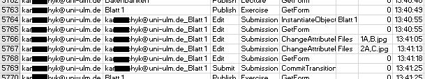
One of the main things we examined for this evaluation was the navigation and interaction chains that could be identified in the logs, as we wanted to ensure that users were not aimlessly searching for information while interacting with the user interface. To this end we wrote a series of macros that analyzed individual chains such as those shown in Fig. 28. The additional columns Previous Timestamp and Time Difference were added to the raw log via formulas. Essentially, the Previous Timestamp column points to the previous timestamp what was caused by the same user, while Time Difference calculates the difference between the current and previous timestamp for said user. As the Time Difference column allows for the identification of large gaps between user interactions, it can be utilized for grouping log entries into coherent user interactions chains.
Assuming a threshold of 2-3 minutes between two log entries as an indicator that a user started a new interaction chain, the excerpt from the log shown in Fig 28 shows two clear interaction chains from two different users, h.r and e.h (redacted to initials). Note that these interaction chains occurred concurrently. Clearly, the starting points of the interaction chains are the row in which h.r has a time difference between timestamps of 2:12:09 (i.e., over 2 hours of inaction), and the row in which e.h has a time difference of 33:17:55 (i.e., over 33 hours of inaction). The interaction chain of h.r starts with a navigation to object instance “Blatt 3333German: Exercise Sheet 3” indicating that he or she had bookmarked the exercise sheet in the browser and navigated to it directly, causing the GetForm action to be logged. Four seconds after loading the form (including page loading time), h.r clicked on the “Create Submission” button generated by the user interface when viewing an exercise sheet. This caused the user interface to execute the InstantiateObjectAndLink method in the process engine, which calls the CORE algorithm (cf. Alg. 1) and creates a new Submission object instance and the necessary relations to the Exercise object instance “Blatt 3” and the Attendance object instance belonging to the user “h.r”. Finally, GetForm is executed for the new Submission to display it in the browser. Note that GetForm is logged twice when navigating to new object instances due to a technical limitation.
At this point, the second interaction chain, belonging to user e.h, starts concurrently. It takes e.h a mere two seconds (including page loading time) after navigating to the lecture “Datenbanken444German: Databases” to navigate to the correct exercise and another two seconds to create the submission using the generated action button. Only 12 seconds later the engine logged e.h adding the file “Blatt3_Data.pdf” to the Files attribute of the new Submission object instance. Four seconds later e.h clicked the “Submit” button that was generated by the user interface as a response to all steps in the lifecycle process of state Edit being provided with values. Note that this action is logged under the internal name “CommitTransition”, which marks the transition of an object instance to a new state, in this case “Submit”. Following the e.h chain further shows that e.h proceeded to navigate back to the Exercise, then forwards again to the submission, presumably to check if it had been submitted correctly (students were told that PHoodle was a prototype after all). Finally, the chain ends after two more log entries showing that e.h navigated up from his or her Submission to the “Datenbanken” Lecture (skipping the “Blatt3” Exercise, i.e. presumably via direct breadcrumb navigation, cf. Fig. 21) and then down into a Download object instance. All the navigation paths made visible by these logs, both up to higher levels and down to lower levels, can be traced back to the data model shown in 7. Furthermore, this allows us to create statistics based on how long users needed to perform individual actions and entire interaction chains. A few of these statistics, such as that it took students an average of just below 23 seconds to upload a submission, are helpful in allowing us to gauge whether the PHILharmonicFlows user interface presented in this article was as simple and efficient to use as the study we conducted in Section 4.1 suggests. In particular, we examined the data and extracted the exact time it took students between having created a Submission object instance and providing values for the Files attribute instance and grouped the times by the Exercises object instances the Submission object instances are related to. The results were that students had completed this step in an average of 28 seconds for exercise sheet 1, 22 seconds for exercise sheet 2, 20 seconds for exercise sheet 3, 19 seconds for exercise sheet 4, and 22 seconds for exercise sheet 5. This clearly shows that a) the students had a clear learning effect after having completed the task for the first time and b) the user interface allowed them to complete their submissions very quickly, regardless of their level of expertise. This is supported by the fact that across all 1163 file uploads the measured learning effect is only statistically significant between the files associated with submissions to the first exercise sheet (~28 seconds) when compared to all other exercise sheets (~19-22 seconds).
In essence, the correlation possibilities and questions that may be answered by examining the PHILharmonicFlows engine logs are manifold, and, together with the empirical study, provide us with the certainty that the users in our real-world deployment could complete their tasks in a timely manner and without having to re-do steps due to process-related limitations. Furthermore, the logs we examined, and the generic logging system in general, provide ample opportunity for future research into topics such as process mining and conformance checking of data-centric processes.
4.3 Discussion and Further Evaluation
So far, we have made one change to the PHoodle process model based on the collected data, which we use to identify limitations of the current concept. In particular, we added a relation between the Tutorial object and the Lecture object, which is already reflected in Fig 3. This is due to the fact that our concept, as explained in Section 3.1, only displays the directly related object instances for a specific context object. As there is no structural reason to have a relation between a Tutorial and a Lecture, as they are already transitively related via Tutor, the relation was left out of the initial model. However, users expect to be able to see their assigned Tutorial when viewing a Lecture, which led to confusion as the users had to first select their Tutor to see their assigned Tutorial. Requiring these minor changes to an object-aware process model, in addition to the necessity of adding relation attributes to enable automatic relation creation, are threats to validity of the solution, as this imposes some constraints on the model for the user interface to function optimally from a usability perspective. Nevertheless, even without any changes, the user interface can be used to interact with any object-aware process, albeit lacking some “comfort” features.
To verify that the presented concepts not only work in the context of the PHoodle e-learning process model, we created a number of different models employing the concepts. One of these is a human resource management system that specifically deals with the recruitment of new job applicants. Without going into too much detail, the data model of the recruitment example consists of the objects Job Offer, Application, Interview, Review, Person, and Employee, which are related to each other as shown in Fig. 29. Once loaded into the runtime user interface, we were able to generate user interfaces such as the one shown in Fig. 30 with no additional changes to our concepts or code.
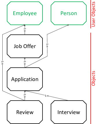
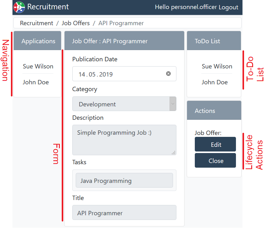
As can be seen in Fig. 30, anyone who was worked with any other PHILharmonicFlows generated user interface, such as PHoodle, can immediately grasp what is shown on screen. The object instance shown is a Job Offer, there are currently two Applications directly related to said Job Offer instance, and the actions show possible state changes to the Close and Edit states that are part of the Job Offer lifecycle process. Furthermore, this information should also be obvious to persons who have not yet worked with a PHILharmonicFlows process (like PHoodle) and have no knowledge whatsoever of any internal details such as the concept, data models and lifecycle processes. We are currently preparing a similarly thorough usability evaluation study of the recruitment model to prove the point that the user interface is self-explanatory for various models.
5 Related Work
While there are related approaches enabling automatic user interface generation, most of them are not from the domain of process management, but can be found in the field of end-user programming, including approaches such as low-code development platforms. Most notably SUPPLE [12] falls into this category, it takes user interface generation and defines it as constrained optimization problem, with the constraints determined by external factors, such as usage patterns, screen sizes, or user accessibility requirements. Basically, a programmer creates a functional interface specification, which is then used, together with the constraints, as input for the SUPPLE system. SUPPLE optimizes the user interface to conform to the constraints, e.g. removing unimportant widgets to increase text sizes for users with vision problems instead. While this is interesting research, core ideas of which could be introduced into the PHILharmonicFlows runtime user interface, it does not offer the same level of process support for end-users as the concepts presented in this article.
A related approach more concerned with the support of users in completing their tasks, than user interface generation, is FLOWer [13]. FLOWer is a tool that implements the case handling process support paradigm. Case handling assumes that workers need access to an entire case or “work object” at any time to complete their tasks. Note that this is in contrast to traditional activity-centric process support paradigms, in which users are only presented with the information they need to complete one specific activity. While FLOWer offers a sophisticated method for work distribution, i.e., generating to-do lists for users based on roles and process state, the user interface itself is not generated directly from the case information. This is the opposite of an approach like SUPPLE, which is only concerned with user interface generation.
[5] proposes the use of transformation patterns between process fragments and the user interface. This allows for rapid user interface development by mapping common patterns found in process models to reusable form elements. Furthermore, users may re-arrange the generated user interface, thereby changing the underlying process model.
6 Summary and Outlook
In summary, the presented contribution sits between these two examples of related work given in Section 5, as it aims not only to offer process-based workflow support, but also generate a user interface with forms, navigation, and high level abstractions for end-users. While there is room for improvement on the design, or even the usability side of the current PHILharmonicFlows end-user interface, the importance of creating an actually usable object-aware process management system can not be stressed enough. This is especially true when considering the research potential that stems from having a prototype of an object-aware process management system that can be deployed in real-world scenarios and utilized, not only by experts, but also end-users for their daily tasks.
Currently, most research into more advanced topics in the business process management field, such as process mining, compliance conformity checking, and the gathering of business intelligence data is done on the plethora of existing activity-centric process engines and paradigms. However, a generic user interface for object-aware processes allows for these research fields to be opened to non-activity-centric processes as we are now able to collect real-world data by deploying object-aware processes in the field.
Further note that the log files generated by users when interacting with the PHILharmonicFlows process engine are very fine-grained, as the writing of individual attributes is logged separately, due to the fact that the entire flow of the form logic is determined by the process engine using the lifecycle processes of the various objects in an object-aware process model. This opens up opportunities for research not available in activity-centric process engines, in which only the data from completed forms attached to activities is communicated to the server.
Due to the fine-grained logs produced, we will be able to apply approaches like machine learning to the engine, offering quality of life improvements such as pre-filling attributes with values based on historical training data or, even more importantly, optimizing the flow of the generated user interface by detecting usage patterns, e.g. in navigation and form usage. The fact that these elements are generated and not hard-coded in the current user interface prototype allows us to research ways to improve their generation using the data we collect from our ongoing studies, real-world deployments, and the aforementioned technologies such as machine learning. Finally, we intend to apply the lessons learned in this research to other projects in the field of data-centric process management.
Acknowledgments
This work is part of the ZAFH Intralogistik, funded by the European Regional Development Fund and the Ministry of Science, Research and the Arts of Baden-Württemberg, Germany (F.No. 32-7545.24-17/3/1)
References
- [1] D. Cohn, R. Hull, Business artifacts: A data-centric approach to modeling business operations and processes, IEEE Data Eng. Bull. 32 (3) (2009) 3–9.
- [2] W. M. P. van der Aalst, M. Weske, D. Grünbauer, Case handling: a new paradigm for business process support, Data & Knowledge Engineering 53 (2) (2005) 129–162.
- [3] K. Swenson, Taming the unpredictable: real world adaptive case management, Future Strategies Inc., 2011.
- [4] V. Künzle, Object-aware process management, Ph.D. thesis, Ulm University (2013).
- [5] J. Kolb, P. Hübner, M. Reichert, Automatically generating and updating user interface components in PAIS, in: 20th Int Conf on Cooperative Inf Systems, no. 7565, Springer, 2012, pp. 444–454.
- [6] S. Steinau, K. Andrews, M. Reichert, The relational process structure, in: 30th Int Conf on Advanced Information Systems Engineering (CAiSE), Springer, 2018, pp. 53–67.
- [7] K. Andrews, S. Steinau, M. Reichert, Enabling fine-grained access control in flexible distributed object-aware process management systems, in: 21st Int Enterprise Distributed Object Computing Conf (EDOC), IEEE, 2017, pp. 143–152.
- [8] D. Müller, M. Reichert, J. Herbst, Flexibility of data-driven process structures, in: BPM’06 Int Workshops, Workshop on Dynamic Process Management (DPM), Springer, 2006, pp. 181–192.
- [9] J. R. Lewis, An after-scenario questionnaire for usability studies: psychometric evaluation over three trials, ACM SIGCHI Bulletin 23 (4) (1991) 79.
- [10] International Organization for Standardization, Ergonomics of human-system interaction, part 210: Human-centred design for interactive systems, https://www.iso.org/standard/77520.html, [Online; accessed 06-April-2020] (2019).
- [11] B. Laugwitz, T. Held, M. Schrepp, Construction and evaluation of a user experience questionnaire, in: Symposium of the Austrian HCI and Usability Engineering Group, Springer, 2008, pp. 63–76.
- [12] K. Z. Gajos, D. S. Weld, J. O. Wobbrock, Automatically generating personalized user interfaces with supple, Artificial Intelligence 174 (12-13) (2010) 910–950.
- [13] P. Berens, The FLOWer Case-Handling Approach: Beyond Workflow Management., Wiley Online Library, 2005, Ch. 15, pp. 363–395.