Compact User-Specific Reconfigurable Intelligent Surfaces for Uplink Transmission
Abstract
Large-scale antenna arrays employed by the base station (BS) constitute an essential next-generation communications technique. However, due to the constraints of size, cost, and power consumption, it is usually considered unrealistic to use a large-scale antenna array at the user side. Inspired by the emerging technique of reconfigurable intelligent surfaces (RIS), we firstly propose the concept of user-specific RIS (US-RIS) for facilitating the employment of a large-scale antenna array at the user side in a cost- and energy-efficient way. In contrast to the existing employments of RIS, which belong to the family of base-station-specific RISs (BSS-RISs), the US-RIS concept by definition facilitates the employment of RIS at the user side for the first time. This is achieved by conceiving a multi-layer structure to realize a compact form-factor. Furthermore, our theoretical results demonstrate that, in contrast to the existing single-layer structure, where only the phase of the signal reflected from RIS can be adjusted, the amplitude of the signal penetrating multi-layer US-RIS can also be partially controlled, which brings about a new degree of freedom (DoF) for beamformer design that can be beneficially exploited for performance enhancement. In addition, based on the proposed multi-layer US-RIS, we formulate the signal-to-noise ratio (SNR) maximization problem of US-RIS-aided communications. Due to the non-convexity of the problem introduced by this multi-layer structure, we propose a multi-layer transmit beamformer design relying on an iterative algorithm for finding the optimal solution by alternately updating each variable. Finally, our simulation results verify the superiority of the proposed multi-layer US-RIS as a compact realization of a large-scale antenna array at the user side for uplink transmission.
Index Terms:
Reconfigurable intelligent surfaces (RIS), large-scale antenna arrays, multi-layer structure, transmit beamformer design.I Introduction
The internet of things (IoT) has attracted much research interest in the communication community. In next-generation networks, the number of access points may reach millions per square kilometer in tele-traffic hotspots [2]. The interactions among smart devices, such as robots, intelligent reconfigurable furniture, and vehicles will require increasing wireless communications quality. In downlink transmissions, massive multiple-input multiple-output (MIMO) systems boost the capacity by employing a large-scale array having hundreds of antennas at the base station (BS) side [3]. It has been verified that massive MIMO systems are capable of achieving orders of magnitude increase in spectral efficiency by simultaneously serving a massive number of users [4].
However, in uplink transmissions, employing a large-scale array at the user side has been considered as unrealistic. Although a large-scale beamformer generates high-gain beams, which increases the channel capacity and enhances the wireless coverage, there is a fundamental dimensionality limit that prevents this idea. Specifically, traditional antenna arrays require numerous radio-frequency (RF) components, like RF chains in the fully digital architecture [5] and phased arrays in the hybrid architecture [6]. Hence this would lead to bulky circuits, high hardware cost, and excessive power consumption at the user side.
As a remedy, the emerging innovative technique of reconfigurable intelligent surfaces (RIS) constituted by a large-scale array developed from meta-materials may be harnessed [7, 8]. The appeal of RISs is that they can enhance the communications in a cost- and energy-efficient way, which provides us with a promising opportunity to construct large-scale arrays in a compact form at the user side.
I-A Prior contributions
Again, a RIS is a large-scale array composed of a large number of passive low-cost elements, which can reflect or transmit the incident electromagnetic waves in the desired directions by appropriately adjusting their phase shifts [9, 10]. In contrast to the traditional energy-hungry RF components (e.g. 250 mW per RF chain) [11], the RIS elements are passive, and yet they can engender the required phase shifts in a relatively energy-efficient way [12, 13, 14, 15, 16]. Since the benefits of RISs have already been verified in practical wireless communications prototypes [17, 18], RISs have been regarded as a promising technique for future 6G wireless communications [19].
The applications of RISs can be generally divided into two broad categories. The first category employs relay-like RISs between the BS and the user for enhancing the transmission links. For example, RISs can provide additional propagation paths and thus can be utilized for improving the transmission reliability by overcoming blockages [9]. Another scenario is considered where multiple BSs and multiple RISs are employed for simultaneously serving multiple users. As a benefit, compared to traditional networks operating without RISs, an improved network capacity and energy efficiency can be achieved [20, 21, 22]. In [23], RISs are used for reducing the transmit power of the BS, which is derived by jointly optimizing the phase shifts of RIS elements as well as the parameters of both the BSs and users. As for the placement of the relay-like RIS, You et al. [24] has investigated the RIS deployment strategies for approaching optimal performance111Note that, although [24] investigated the practicability of employing relay-like RISs close to the user, which seems similar to the proposed concept of user-specific RIS (US-RIS) in Subsection II-A, it can still be categorized as a base-station-specific RIS (BSS-RIS). The differences between these two contributions are explicitly detailed in Subsection II-B, Table I..
The second category employs RISs near the BS for analog beamforming at a low cost and frugal power consumption. The authors of [25] propose a RIS-based transmit precoding architecture for maximizing the sum-rate, where the phased arrays are replaced by the RIS at the BS side. As a further development, the authors of [26] utilize a RIS at the BS side for beamforming relying on the optimal phase shifts. In these contributions, RISs serve as part of a new BS type that transmits/receives signals at a reduced cost and power consumption [25, 26].
In a nutshell, both the above two categories utilize RISs for improving the communication performance of the cellular network, hence we refer to them as base-station-specific RISs. By contrast, RISs have not been employed at the user side in the open literature.
I-B Our contributions
To circumvent the dimensionality limit of employing a large-scale array at the user side, we propose the concept of user-specific RISs, where the RIS is employed at the user side for enhancing the user’s capability in uplink transmissions222Simulation codes are provided to reproduce the results in this paper: http://oa.ee.tsinghua.edu.cn/dailinglong/publications/publications.html.. Specifically, the contributions of this paper can be summarized as follows.
-
•
We propose the concept of US-RIS to break the dimensionality limit and to facilitate the employment of a large-scale array at the user side. In contrast to the existing BSS-RISs, which are utilized for improving the communication performance of the cellular network, this is the first use case of RIS dedicated to the user side.
-
•
We propose and analyze a multi-layer structure to realize US-RISs by considering the space-limited characteristics of users. Explicitly, in contrast to existing RISs, where only the phase of the signal can be adjusted, the amplitude of the signal can also be partially controlled. This provides us with an additional degree of freedom (DoF) for RIS beamforming design.
-
•
We then formulate the associated signal-to-noise ratio (SNR) maximization problem of US-RIS-aided communications. Due to the non-convexity introduced by the multi-layer RIS structure proposed, we develop a multi-layer transmit beamformer design that can control both the phase and the amplitude of the transmitted signal. Specifically, the proposed multi-layer transmit beamformer design relies on an iterative optimization algorithm for finding the optimal solution to the problem formulated. Finally, our simulation results verify the benefits of the proposed multi-layer US-RIS as a realization of a large-scale array at the user side for uplink transmission.
I-C Organization and notation
Organization: The rest of the paper is organized as follows. In Section II, we propose the basic concept of US-RIS. Then, we conceive a novel architecture relying on this multi-layer US-RIS. In Section III, we theoretically analyze the performance of the proposed multi-layer structure. In Section IV, we consider a US-RIS-aided communications scheme and formulate the corresponding SNR maximization problem. The multi-layer transmit beamformer design is proposed as an iterative algorithm for solving the problem formulated, where each variable is updated in an alternating fashion. In Section V, simulation results are provided for quantifying the performance of US-RIS-aided communications, demonstrating the practical realization of a large-scale array at the user side for uplink transmission. Finally, in Section VI, we provide our conclusions followed by promising future research ideas.
Notation: and denote the set of complex, real, and positive real numbers, respectively; represents the set of integers ; and denote the inverse, conjugate, transpose, and conjugate transpose of matrix , respectively; is the -norm of vector ; is the normalized vector of , i.e., ; and denote the phase angle and exponential representation of each element of the complex vector , respectively; denotes the amplitude of a complex scalar ; is the diagonal operation; represents the complex multivariate Gaussian distribution with the mean and the variance ; denotes the zero vector; denotes the identity matrix; is the eigenvector of matrix corresponding to its largest eigenvalue.
II System Model
To realize a large-scale array at the user side at a low cost and low power consumption, in this section, we propose the concept of US-RISs. Specifically, the concept is introduced in Subsection II-A. Then, we propose a novel architecture relying on a multi-layer US-RIS and compare it to existing BSS-RISs in Subsection II-B. Finally, in Subsection II-C, we develop the system model of US-RIS-aided communications.
II-A Concept of US-RIS
As the terminology suggests, US-RIS is a hardware technique conceived for constructing a large-scale array at the user side.
(a) (b) (c)
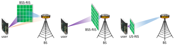
Again, traditional applications of RISs in wireless communications are limited to employing RISs between the BS and the user or alternatively, at the BS side, as shown in Fig. 1 (a) and (b), respectively. In Fig. 1 (a), a relay-like RIS is used to “reconfigure” the wireless channels for enhancing the multipath diversity by mitigating blockages. By contrast, in Fig. 1 (b), a RIS is employed at the BS side for beamforming. Again, both of these two applications aim for improving the performance of the cellular network, which are termed as BSS-RISs.
By contrast, here we conceive the US-RIS concept shown in Fig. 1 (c). In contrast to the traditional BSS-RISs, US-RISs are employed close to the user as a realization of a large-scale array at the user side. Given their cost- and energy-efficient characteristics, US-RISs are eminently suitable for compact user-side employment, which dispels the myth that a user can hardly harness a large-scale array, considering the inherent cost- and power-constraints.
II-B Architecture
(a)
(b)
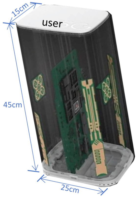
To illustrate a potential US-RIS construction, Fig. 2 gives an example based on a customer-premises equipment (CPE). Specifically, this CPE facilitates access to communication routers, network switches, and networking adapters. Fig. 2 (a) portrays a real-world CPE model of size . The physical size of this transmissive US-RIS is beneficially reduced by constructing a multi-layer structure. Fig. 2 (b) shows the axonometric construction of the US-RIS, where three layers of RISs are vertically stacked in front of the CPE in order to form a multi-layer structure, with a gap between adjacent vertical layers. In this way, the overall size of the resultant US-RIS-aided CPE becomes , which may be deemed acceptable for a domestic installation. Note that the number of layers and the inter-layer gaps are flexible in practical applications, depending on the dimensions of the user equipment, the trade-off between cost and performance, etc. Naturally, the entire structure should be hosted by an enclosure, surrounded by absorbing materials to reduce the energy loss and to protect the internal channel from external interference. As usual, the controller is informed by the channel estimator on how to configure the phase shifts of US-RISs. For practical hardware implementation, [27] proposes a similar construction for implementing a deep neural network (DNN), which may be adopted for realizing this architecture.
| Aspect | BSS-RIS | US-RIS |
|---|---|---|
| Location | BS | user |
| Controller | one/multiple BS(s) | one user |
| Beneficiary | one/multiple user(s) | one user |
| Operating mode | mainly reflective | transmissive |
| Structure | single-layer | single/multi-layer |
| Size | large | compact |
| EAR | small | big |
To clarify the characteristics of this novel user-side architecture and the differences between BSS-RIS and US-RIS, we summarize their key aspects in Tab. I and compare them as follows.
-
•
Location, controller, and beneficiary: According to their terminologies, the most essential difference between BSS-RIS and US-RIS is their location. The BSS-RIS is primarily proposed for improving the overall channel capacity of the cellular network, while US-RIS at the user side is transmissive and may also be regarded as an integral component of the user. Moreover, it has been theoretically shown that due to the intrinsic “multiplicative fading” effect of passive RIS [28, 29], the RIS is preferred to be employed near the BS or the user to minimize the pathloss [30, 31]. Thus, we place the US-RIS near the user is in line with the results of RIS placement optimization. Also, both the controller and the beneficiary of the BSS-RIS and US-RIS are different. The BSS-RIS is controlled by one/multiple BS(s) in the system and it cooperatively serves one/multiple user(s) at the same time. By contrast, for the US-RIS, both the controller and the beneficiary is the same user. Both the beamforming design and phase-shift control are carried out at the US-RIS.
-
•
Operating mode and structure: Most BSS-RISs tend to be reflective arrays [20, 21, 23, 25], while our US-RIS is a transmissive array operating under a tight space constraint at the user side [32]. For US-RIS, the multi-layer structure is conceived for further improving the array gains attained in a limited space. To elaborate, in contrast to the existing single-layer structure, which can only adjust the phase of the incident signal, our multi-layer structure has the advantage that it facilitates partial amplitude control of the radiated signals. This feature provides a new DoF for beamforming design as a structural benefit, which will be detailed in Section III.
-
•
Size and element activation ratio (EAR): In BSS-RIS-aided communications, the size of the BSS-RIS is expected to be very large, which is not practical for the user. To limit the user equipment’s dimension and power consumption, each layer of the US-RIS should be much smaller than a BSS-RIS. However, the proposed multi-layer structure has a compact size. Concretely, the multi-layer RIS simultaneously controls the phase shifts of the different RIS layers. We now proceed by introducing the new metric of element activation ratio (EAR), which explicitly quantifies the particular fraction of activated elements of a transmissive RIS. Specifically, in this ratio, we count an element as being “activated”, if its power is higher than a threshold percentage of the average power333Under this definition, a RIS will have an EAR 100% with threshold percentage when each element has a radiated power higher than of the average power, while a RIS will have the minimum EAR, when a single element radiates all the power.. In Subsection V-D, we will provide experimental EAR results. Apart from the compact structure of our US-RIS, a further particular benefit of the proposed multi-layer architecture is that it is capable of reducing the pilot overhead required for channel estimation, since the channels experienced by the parallel US-RIS layers are similar and can be estimated in advance using the methods of [33] for example.
II-C System model of US-RIS-aided communications
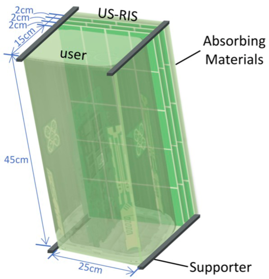
Let us consider the US-RIS-aided communications scenario of Fig. 3, where a multi-layer US-RIS is used for enhancing the uplink transmission from the user to the BS. Assume furthermore that the user and the BS are equipped with transmit antennas and receive antennas, respectively. The US-RIS is composed of layers having elements on the -th layer. Without loss of generality, we assume444The multi-layer precoding design of US-RIS proposed in Section IV is unchanged even if the number of elements on each layer is different. However, it will affect the performance of communications. The discussion about the performance against the number of elements on each layer is left for future work. that is equal to for all . Finally, we denote the -th TA element on the US-RIS’s -th layer as the -th TA element.
We denote the transmitted uplink symbol by . The symbol is firstly processed by the uplink transmit beamforming (UL-TBF) vector of Fig. 3, subject to the power constraint before transmission. Only the user-RIS-BS line-of-sight (LoS) link is considered, while all other possible links are neglected. To elaborate briefly on this assumption, since the user and the US-RIS are wrapped in a protecting enclosure, the transmitted signal must penetrate the multiple transmissive layers to be received at the BS555 Nonetheless, the user-BS link can also be assumed to exist, depending on the practical architecture. The proposed transmit precoder design can be readily extended to the scenario, where this user-BS link exists. . Let us denote the transmit phase shifter (TPS) matrix of US-RIS’s -th layer by
| (1) |
where of Fig. 3 is the phase shift of the -th element and is the feasible set of the transmission coefficients (TC). In this paper, we consider the widely used TC set of
| (2) |
which indicates that only the phase can be controlled independently and continuously [23]. Therefore, the signal received by the BS can be modeled as
| (3) |
where denotes the loss factor when the electromagnetic wave penetrates each layer. Furthermore, and of Fig. 3 denote the frequency-domain channels spanning from the US-RIS’s -th layer to the BS, from the user to the US-RIS’s first layer, and from the US-RIS’s -st layer to the -th layer, for all , respectively. Still referring to (3), denotes the additive white Gaussian noise (AWGN) introduced at the BS receiver, where is the noise power. Finally, the BS receiver combines the signal gleaned from antennas using a receiver combining (RC) vector of Fig. 3. Thus, the uplink signal combined at the BS receiver can be represented as
| (4) |
To illustrate the benefits of the US-RIS based on this system model666The multi-layer structure can be applied at the user side or the BS side following a similar system model, and it can bring about the above-mentioned structural benefits at both sides., the theoretical analysis including the achievable SNR of our US-RIS-aided system will be provided in Section III and Section IV, respectively.
III Performance Analysis on Multi-Layer Structure
In this section, we provide further analysis and discussions on the firstly proposed multi-layer structure of RIS. In Subsection III-A, we theoretically analyze the performance of the proposed multi-layer US-RIS by considering a simplified system. Then, in Subsection III-B, we summarize and compare the existing contributions about the system with multiple cooperative RISs.
III-A Theoretical analysis
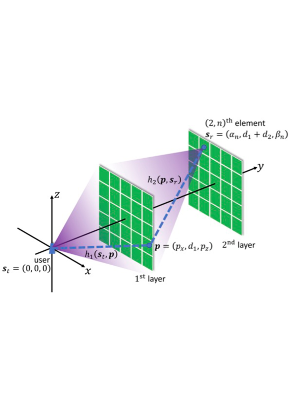
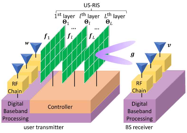
For the proposed multi-layer US-RIS, let us consider a simplified system where a multi-layer US-RIS having layers is employed to assist the uplink transmission from a single-antenna user, as shown in Fig. 4. Let us denote the number of elements in each layer by , where each element is of size . The position of the user is , and the US-RIS’s two layers are positioned at the plane and respectively, with their boundaries parallel to the coordinates and their geometric centers on the -axis. Then, the position of each element is fixed. Specifically, for the -th element of US-RIS, the position of the center can be written as , where and are explicit functions with respect to . Thus, the region enclosed by the -th element can be represented as
| (5) |
We assume that, for single-layer RISs, only the phase shift of each element can be controlled continuously. However, for the multi-layer structure, the power distribution of the second layer can be adjusted by controlling the phase shifts on the first layer, so that the radiated power can be focused on specific elements of the second layer. This allows the amplitude of the signals penetrating multi-layer US-RISs to be controlled to some extent.
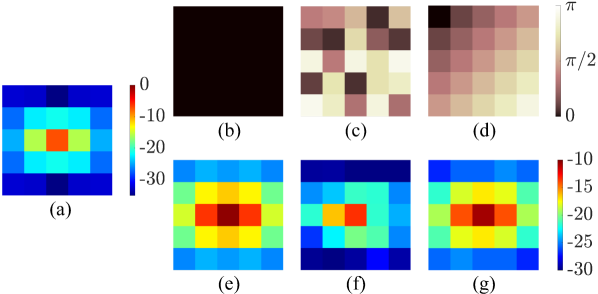
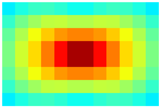
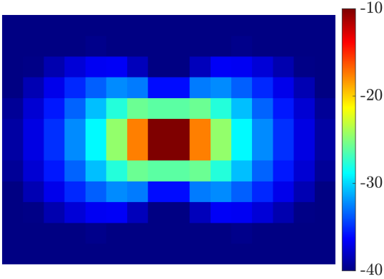
In order to understand this intuitively, a numerical example is given Fig. 5. Specifically, the power distribution of the signal received on the first layer is shown in Fig. 5 (a). Note that, in contrast to the far-field case where the power is uniformly distributed, the power distribution shown in Fig. 5 (a) is different, since the first layer lies close to the user, and thus the pathloss between the user and RIS elements at different positions is not the same. Given the different phase-shift configurations on the first layer displayed in Fig. 5 (b)-(d) (no phase-shift, random phase-shift, and gradual phase-shift, respectively), the patterns of power distributions on the second layer become different as shown in Fig. 5 (e)-(g), indicating that the power distribution can be controlled by multi-layer precoding. Equivalently, it can be readily seen that the amplitude term of the signals penetrating the multi-layer US-RIS can be controlled to some extent, indicating that the a new DoF is granted for our US-RIS-aided transmit beamformer design. The result is different from the far-field case, since when the power is uniformly distributed, pure phase-shift control of the RIS is sufficient for the beamformer. Next, we formally state our theoretical result in Lemma 1, and quantitative analysis will be provided in Subsection V-D.
Lemma 1
Upon denoting the signal radiated from the -th element of the US-RIS by , the phase of can be adjusted to any desired angle in , while the amplitude of can be adjusted in the range , where we have:
| (6) | ||||
Proof:
Remark 1
In Lemma 1, we have stated that, for a specific , the phase and amplitude of can be controlled in a range. However, due to the coupling of , the phases of cannot be controlled independently since the amplitudes of exhibit correlation. The effect of this correlation is set aside for future research.
III-B Comparison between systems with multiple cooperative RISs
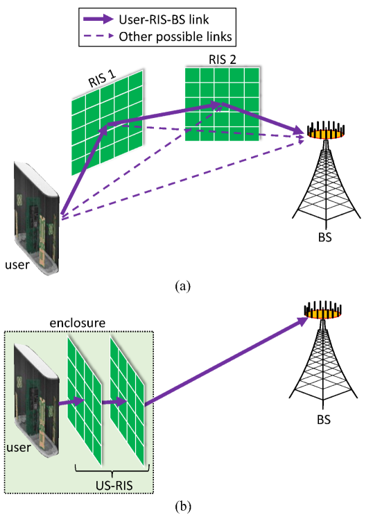
As revealed in the above theoretical analysis, when relying on collaborative phase shift control in our multi-layer US-RIS, the amplitude term of signals can be partially controlled. Indeed, several other contributions on multiple cooperative BSS-RIS-aided communications have also done so [34, 33]. As shown in Fig. 6 (a), iin multiple cooperative BSS-RIS-aided communications, multiple relay-like reflective BSS-RIS are employed for enhancing the system’s performance, and the phase shift controls of different RISs are cooperatively optimized to achieve higher array gains. In contrast to BSS-RIS-aided communications, the proposed multi-layer US-RIS-aided regime employs multiple transmissive RISs at the user side, as shown in Fig. 6 (b).
Indeed, both systems are capable of increasing array gains by cooperative beamformer design upon mitigating the “multiplicative fading” effect, which becomes aggravated by the multiple reflections/transmissions. In multiple cooperative BSS-RIS-aided communications, one can increase the number of elements in relay-like BSS-RISs to compensate for the pathloss, but in multi-layer US-RIS-aided systems, the number of RIS elements is limited by the space constraint. However, similar to the analysis in [30, 31], the US-RIS are employed close to the user, which has the beneficial effect of reducing the multiplicative fading.
Moreover, since the multi-layer US-RIS is composed of transmissive surfaces, the energy loss when the signal penetrates the surface would be higher than that of the signal reflected from a surface. However, the proposed multi-layer US-RIS-aided system has a valuable benefit and an associated difference in the system model, since the signal is only transmitted through the user-RIS-BS link thanks to the enclosure-based construction. By contrast, the multiple cooperative BSS-RIS-aided system comprises many other possible links, including all the single-reflection links and the direct link. Hence, additional channels have to be estimated, which requires more pilots.
IV Multi-Layer Transmit Beamformer Design
To further investigate the proposed US-RIS, in this section, we extend our discussions to the more general case of and . Based on the system model developed, we first formulate our SNR maximization problem in Subsection IV-A, which is non-convex. We will circumvent this challenge by developing a multi-layer transmit beamformer design relying on an iterative algorithm. Then, the overview of our multi-layer transmit beamformer design is provided in Subsection IV-B, while the intricate details of the optimization process are discussed in Subsection IV-C. We also discuss the possible extension of the proposed method to the multi-user case in Subsection IV-D. Finally, the convergence and the computational complexity of the multi-layer transmit beamformer design are analyzed in Subsection IV-E.
IV-A Problem formulation
Based on the system model of Fig. 3 in Section II, we aim for maximizing the detection SNR of the proposed US-RIS-aided system. Observe from the uplink signal combined at the BS as shown in (4) that an equivalent noise contribution of is introduced, which obeys . Hence, the detection SNR at the BS can be represented as
| (7) |
Then, given the maximum transmit power constraint of the user and phase shifts constraint at the US-RIS, the SNR maximization problem is formulated as
| (8a) | ||||
| s.t. | (8b) | |||
| (8c) | ||||
Due to the non-convexity of the objective function (8a) and the constraint (8c), the joint optimization of both the RC vector , as well as of the US-RIS TPS matrices , and of the UL-TBF vector is challenging. To tackle this challenge, we propose an iterative algorithm as our multi-layer transmit beamformer design.
IV-B Overview of the proposed multi-layer transmit beamformer design
The algorithm of solving this joint optimization problem (8) is summarized in Algorithm 1. Specifically, given the input channel matrices and parameters, the coupled variables , , and can be optimized by alternately updating one variable with the other variables fixed. Once convergence of the objective function is reached, the iterations are curtailed, and the optimal beamformer design is found. Generally, the computation of the multi-layer transmit beamformer design takes place at the BS side, and the BS should transmit the optimal UL-TBF vector and the TPS matrices back to the user.
IV-C Optimal UL-TBF, TPS, and RC of Fig. 3
In this subsection, we derive the closed-form expression of the optimal solution corresponding to each variable. For ease of notation, we first define
| (9) |
Then, the updates of different variables are respectively provided as follows.
IV-C1 Optimal RC
For determining the RC vector of Fig. 3, while fixing all the other variables, the optimization problem (8) can be equivalently reformulated as
| (10) |
where is a positive semidefinite matrix. Based on matrix analysis, the maximum SNR can be achieved when is the eigenvector of , corresponding to its largest eigenvalue, which is formulated as
| (11) |
IV-C2 Optimal US-RIS TPS
For the TPS matrix , since is a diagonal matrix and is a column vector, we have
| (12) |
By exploiting the transformation (12), the SNR can be rewritten as
| SNR | (13) | |||
Because of the constraint (8c), the optimal value of is obtained when all entries of have the complementary phase angle as the vector multiplied on the left, which is expressed as
| (14) |
IV-C3 Optimal UL-TBF
Finally, for the UL-TBF vector , we first consider the optimization of the normalized vector , i.e.,
| (15a) | ||||
| (15b) | ||||
We then obtain the optimized as
| (16) |
Upon considering the constraint (8b) and the relationship between the optimized for the subproblem (8) and the optimized for the subproblem (15), we arrive at
| (17) |
IV-D Extension to multi-user case
In Subsection IV-B and IV-C, we have proposed a multi-layer transmit beamformer design for US-RIS-aided communications that supports a single multi-antenna-aided user. For the multi-user case, we can simply extend the analysis relying on signal model (4). Explicitly, we may assume that users are supported by an -layer US-RIS having elements on each layer. Upon extending our notations in Subsection II-C, let us assume that denote the independent UL-TBF vector and TPS matrices for the -th user, respectively. Then, the signal combined at the BS receiver can be rewritten as
| (18) |
where and denote the channels corresponding to the -th user spanning from the US-RIS’s -th layer to the BS and from the user to the US-RIS’s first layer, respectively. Therefore, the new objective of the joint optimization, which now becomes the sum-rate of all users, can be represented as
| (19) |
where the received signal-to-interference-plus-noise ratio (SINR) of the -th user at the BS can be represented as
| (20) | ||||
Following the same constraints of the maximum transmit power and the phase shifts as for the US-RIS, the new optimization problem can be solved by our proposed multi-layer transmit beamformer design of the single-user case by employing standard fractional programming methods to tackle the non-convex nature of the objective. However, the full characterization of this multi-user scenario requires a full journal paper to be conceived in our future research.
IV-E Algorithm analysis
IV-E1 Convergence analysis
For the proposed multi-layer transmit beamformer design, we adopt the general assumption that only the phase shifts of the elements can be continuously controlled. Under this assumption, if the variables are alternately updated according to (11), (14), and (17), which is the optimal solution of the corresponding subproblem with all the other variables fixed, the objective function, namely the SNR, will increase monotonically, hence indicating the strict convergence of the multi-layer transmit beamformer design.
IV-E2 Complexity analysis
The overall computational complexity of the proposed multi-layer transmit beamformer design is dominated by the updates of the variables , , and , as shown in (11), (14), and (17), respectively. Note however that, the terms associated with different and have strong correlation that may be exploited for reducing the redundancy of the repeated matrix multiplications. Specifically, all terms involved in (11), (14), and (17) can be obtained throughout the computational processes of and , hence only the computational complexities of and actually count in the terms of the parameter updates.
| Variable | Complexity |
|---|---|
We have summarized the computational complexities of the variables in TABLE II. Since the number of RIS elements is usually high [35], we can reasonably assume that and . Furthermore, due to the loss factor characterizing the process when the electromagnetic waves penetrate each layer, the number of layers must not be large compared to , i.e. we have . Under these assumptions, the overall complexity of the proposed multi-layer precoding design in a single iteration may be approximated by . For comparison, the complexity analysis of the beamformer design in BSS-RIS-aided communications can be regarded as a special case of the US-RIS-aided scenario, where the BSS-RIS has a single-layer structure associated with elements, which is the same as the total number of elements in our US-RIS. Therefore, the complexity of a single iteration in the multi-layer transmit beamformer design of BSS-RIS-aided communications is . Since we have , the computational complexity of the proposed multi-layer transmit beamformer design is almost the same as that of the traditional BSS-RIS-aided scheme, which is affordable in practice.
V Simulation Results
In this section, we provide extensive simulation results for quantifying the performance of the proposed US-RIS concept and of the corresponding multi-layer transmit beamformer design for US-RIS-aided communications. The simulation scenario is introduced first in Subsection V-A. Then, numerical results are discussed in the following subsections.
V-A Simulation setup
(a) (b)
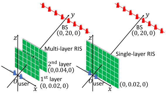
For simplicity but without loss of generality, we consider a 3-D scenario where different types of RISs are employed for uplink transmission from the user to the BS. Specifically, the topology considered is shown in Fig. 7. Let denote the wavelength of the transmitted uplink signal. We assume that both the user and the BS are equipped with a uniform linear array (ULA) having and antennas, respectively, where the distance between the adjacent elements is . A multi-layer US-RIS, with layers and elements on each layer, is used for enhancing the user’s uplink transmission, as shown in Fig. 7 (a). For comparison, we consider another two cases, where a single-layer US-RIS and a single-layer reflective BSS-RIS having elements are respectively used at the same position as the multi-layer US-RIS’s first layer shown in Fig. 7 (b). The total number of elements in the multi-layer US-RIS, single-layer US-RIS, and single-layer BSS-RIS are the same, and they are all uniform planar arrays (UPAs), where the elements of size are closely packed with no spacing [36]. We assume that the user, the multi-layer US-RIS’s first layer (located at the same position as the single-layer US/BSS-RIS), the multi-layer US-RIS’s second layer, and the BS are located with their centers at , , , and , respectively. The frequency of the transmitted signal is set to . The noise power is set to . The loss factor when a wave penetrates a transmissive RIS is set to .
As for the channel model, we categorize all channels involved into two types. The RIS-BS channel is the Type I channel which is a far-field channel assumed to obey the free-space propagation, where an ideal transmit antenna sends a signal to a lossless receive antenna. The pathloss of the Type I channel can be directly obtained from Friis’ formula. On the other hand, the user-RIS and RIS-RIS channels are termed as the Type II channels. To elaborate, the Type II channel is the near-field channel spanning from a lossless antenna to an element of the UPA under the LoS assumption. The lossless transmit antenna can be either an element of a ULA or an element of a UPA, corresponding to the user-RIS and RIS-RIS channels. For the pathloss of the Type II channel, we adopt the exact expression introduced in [37, Lemma 1], which calculates the free space channel gain from a lossless antenna to a planar array. Note that, we only consider the user-RIS-BS links, and the other potential links are ignored, as mentioned in Section II.
Finally, we assume for the proposed multi-layer transmit beamformer design that the channel state information (CSI) is perfectly known [38, 20], which can be estimated through RIS-based channel estimation and channel feedback methods in practice [39, 40, 41]. Specifically, in US-RIS-aided communications, the channel spanning from the user to the US-RIS and that between adjacent layers of the US-RIS can be estimated beforehand, thanks to stability ensured by the enclosure. As for the initializations, all RISs are initialized by random phase values in the feasible set, while the UL-TBF and RC vectors are initialized as ones in our iterative algorithm.
V-B Performance of the US-RIS-aided communications
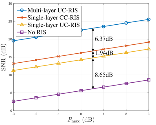
In Fig. 8, we portray the detection SNR versus the maximum transmit power for different RIS scenarios. We also consider a “No RIS” benchmarker for comparison [20], where the RIS shown in Fig. 7 is removed but the optimization of UL-TBF vector and RC vector based on the Type I UE-BS channel is retained.
Observe from Fig. 8 that the SNR versus the maximum transmit power exhibits a near-linear relationship, which can also be observed from the parameter updates (11), (14), and (17). Therefore, we can readily compare different scenarios with the power constraint fixed. The associated differences are marked in Fig. 8. Observe that the communication without RISs has the lowest SNR, illustrating that all three RIS scenarios can substantially improve the uplink transmission. Another observation is that the single-layer US-RIS-aided communications has a loss compared to its single-layer BSS-RIS-aided counterpart, which is caused by the loss when a wave penetrates the RIS. Moreover, the multi-layer US-RIS-aided system achieves an increase of detection SNR over its single-layer US-RIS-aided counterpart. Note that in this content we assume both US-RIS structures to have the same total number of RIS elements, so the DoF in phase exploited by our transmit beamformer design is the same. Thus, logically, the increment of detection SNR arises from the additional DoF in amplitude provided by the multi-layer structure, which is an explicit benefit over the conventional single-layer structure that we have shown theoretically.
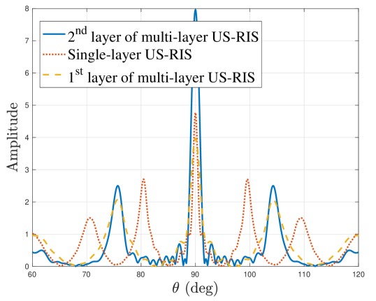
For further characterizing the multi-layer structure, in Fig. 9 we present the radiation pattern of different RISs and compare the quality of the beam by comparing their mainlobes and sidelobes. Naturally, a beam having lower sidelobes and a higher mainlobe is preferred. Observe from Fig. 9 that the transmitted beam of the first layer in the multi-layer US-RIS has a lower mainlobe than the single-layer US-RIS, which is caused by the reduced number of elements in the first layer of the multi-layer US-RIS. However, after penetrating the second layer and obtaining a new DoF in amplitude terms, the mainlobe to sidelobe ratio is considerably improved. The above results coincide well with our theoretical analysis provided in Section III.
V-C Convergence of the proposed multi-layer transmit beamformer design
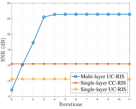
Recall from Subsection IV-E1 that, the proposed multi-layer transmit beamformer design exhibits monotonic convergence. In Fig. 10, we further characterize its convergence in the simulation scenario considered. The results of Fig. 10 clearly illustrate that, the proposed multi-layer transmit beamformer design for multi-layer US-RIS converges within to iterations, while the conventional single-layer BSS-RIS-aided scheme converges within to iterations. However, our solution outperforms the latter after the first iteration.
V-D EAR Analysis on RIS
(a) (b) (c)
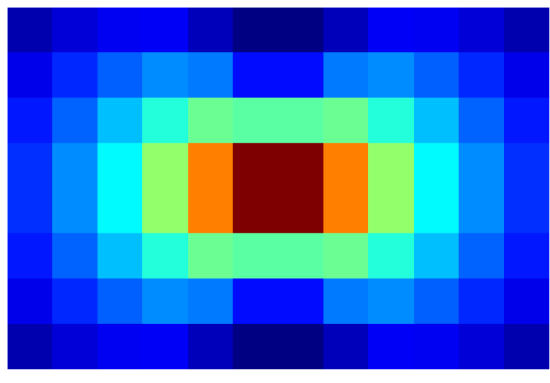
To further reveal the benefits of the multi-layer structure in controlling the amplitude of the signal, the power distribution of both multi-layer and single-layer US-RIS are presented in Fig. 11. Observe from Fig. 11 (a) and (c) that both in the first layer of the multi-layer US-RIS and in the single-layer US-RIS, the central elements are assigned most of the power, while the non-central elements have a limited contribution. By contrast, as shown in Fig. 11 (b), the power distribution is transformed to a more balanced power pattern in the second layer of US-RIS with the aid of the phase shift control of the first layer. Although the power of the central elements is reduced, the elements along the edges become more influential.
To quantify this phenomenon, we apply the EAR metric defined in Subsection II-B. Explicitly, the EARs of different RISs with a threshold percentage are shown in Fig. 11. The first layer of the multi-layer US-RIS has an EAR of , which is higher than that of the single-layer US-RIS having an EAR of , because the first layer of the multi-layer US-RIS has fewer elements. Furthermore, as a benefit of the multi-layer structure, the EAR of the second layer of the US-RIS is , and the overall EAR of the multi-layer US-RIS is , which is twice higher than that of the single-layer US-RIS. The obvious improvement in EAR also demonstrates the ascendancy of the proposed architecture with multi-layer structure.
VI Summary and Conclusions
In this paper, we have proposed the concept of US-RIS to circumvent the space-limit of employing a large-scale array at the user side. In contrast to the existing BSS-RISs, we have proposed a solution that is suitable for the user side. Based on this concept, we have further proposed a novel architecture with the aid of a multi-layer US-RIS. Our theoretical analysis has demonstrated that the amplitude of the signal penetrating the multi-layer US-RIS can also be partially controlled, which equips us with a new DoF. Furthermore, we have formulated the associated SNR maximization problem in the US-RIS-aided communications and have proposed the corresponding multi-layer transmit beamformer design that alternately finds the optimal solution for each variable. Our simulation results have verified the superiority of the proposed multi-layer US-RIS as a realization of a large-scale array at the user side for uplink transmission.
However, a whole spate of open problems associated with multi-layer US-RIS requires further investigations in our future work. For example, the theoretical analysis of this appealing multi-layer structure is based on the assumption that the RIS phase shifts can be controlled continuously, while in practice only discrete phase shifts can be realized [42]. Furthermore, the RIS-element correlation has been neglected in this study, which requires special attention. Finally, for practical hardware implementation considerations, the number of RIS elements in each layer is limited by the user’s dimensions, and the design of transmissive RIS should reduce the energy loss and prohibit possible signal reflection.
Appendix A Proof of Lemma 1
Following the notations in Section III, the proof proceeds in two steps. In the first step, we derive the closed-form expression of by integration. In the second step, under the assumption of controllable US-RIS phase shift matrices, we analyze the range of phase and amplitude of , respectively.
A-A Closed-form expression of
Denote the channel spanning from the point source at the user to the arbitrary receiver point on the US-RIS’s first layer and the channel spanning from to the center of the -th element by and , respectively. The expression of and can be written as
| (21a) | ||||
| (21b) | ||||
where denotes the wavelength and
| (22a) | ||||
| (22b) | ||||
represent the channel gain along the -direction, respectively [43, 37]. Upon integrating over all receive points on the US-RIS’s first layer and considering the phase shift of the -th element, we arrive at the closed-form expression of
| (23) |
A-B Range of phase and amplitude
As for the range of the phase , recall from (23) that, since the phase of can be controlled continuously in , the phase of can also be controlled continuously in .
As for the range of amplitudes , we discuss the control strategy of RIS required for achieving the minimum of and the maximum of , respectively. Note that the phase shift matrix does not influence the amplitude of , hence we can focus our attention on the phase shift matrix .
On the other hand, to obtain the minimum amplitude, we construct a phase matrix that results in . A potential construction method is constituted by the following. We define the four symmetric elements centered at
as a quaternion . The elements on the first layer can then be divided into quaternions that do not have intersection with each other. We will show that, for each quaternion , there exist values which satisfy
| (25) |
Then, for each quaternion, we can construct a group of phase shifts , which has no contribution to in (23). With the aid of this process, we obtain a solution of that satisfies .
Acknowledgments
We would like to thank Richard MacKenzie from BT Group plc, Mo Hao from Tsinghua SEM Advanced ICT LAB, and Dr. Chenghong Zhuang for their helpful discussion and support of this work.
References
- [1] K. Liu, Z. Zhang, and L. Dai, “User-side RIS: Realizing large-scale array at user side,” in Proc. 2021 IEEE Global Communications Conference (IEEE GLOBECOM’21), 2021, pp. 1–6.
- [2] M. Giordani, M. Polese, M. Mezzavilla, S. Rangan, and M. Zorzi, “Toward 6G networks: Use cases and technologies,” IEEE Commun. Mag., vol. 58, no. 3, pp. 55–61, Mar. 2020.
- [3] F. Rusek, D. Persson, B. K. Lau, E. G. Larsson, T. L. Marzetta, O. Edfors, and F. Tufvesson, “Scaling up MIMO: Opportunities and challenges with very large arrays,” IEEE Signal Process. Mag., vol. 30, no. 1, pp. 40–60, Jan. 2013.
- [4] T. L. Marzetta, “Noncooperative cellular wireless with unlimited numbers of base station antennas,” IEEE Trans. Wireless Commun., vol. 9, no. 11, pp. 3590–3600, Nov. 2010.
- [5] O. El Ayach, S. Rajagopal, S. Abu-Surra, Z. Pi, and R. W. Heath, “Spatially sparse precoding in millimeter wave MIMO systems,” IEEE Trans. Wireless Commun., vol. 13, no. 3, pp. 1499–1513, Mar. 2014.
- [6] K. B. Letaief, W. Chen, Y. Shi, J. Zhang, and Y.-J. A. Zhang, “The roadmap to 6G: AI empowered wireless networks,” IEEE Commun. Mag., vol. 57, no. 8, pp. 84–90, Aug. 2019.
- [7] S. Hu, F. Rusek, and O. Edfors, “Beyond massive MIMO: The potential of data transmission with large intelligent surfaces,” IEEE Trans. Signal Process., vol. 66, no. 10, pp. 2746–2758, Oct. 2018.
- [8] C. Pan, H. Ren, K. Wang, J. F. Kolb, M. Elkashlan, M. Chen, M. Di Renzo, Y. Hao, J. Wang, A. L. Swindlehurst, X. You, and L. Hanzo, “Reconfigurable intelligent surfaces for 6G systems: Principles, applications, and research directions,” IEEE Commun. Mag., vol. 59, no. 6, pp. 14–20, 2021.
- [9] E. Basar, M. Di Renzo, J. De Rosny, M. Debbah, M.-S. Alouini, and R. Zhang, “Wireless communications through reconfigurable intelligent surfaces,” IEEE Access, vol. 7, pp. 116 753–116 773, Aug. 2019.
- [10] Y. Liu, X. Mu, J. Xu, R. Schober, Y. Hao, H. V. Poor, and L. Hanzo, “STAR: Simultaneous transmission and reflection for 360∘ coverage by intelligent surfaces,” arXiv preprint arXiv:2103.09104, Mar. 2021.
- [11] P. V. Amadori and C. Masouros, “Low RF-complexity millimeter-wave beamspace-MIMO systems by beam selection,” IEEE Trans. Commun., vol. 63, no. 6, pp. 2212–2223, Jun. 2015.
- [12] C. Liaskos, A. Tsioliaridou, A. Pitsillides, S. Ioannidis, and I. Akyildiz, “Using any surface to realize a new paradigm for wireless communications,” Commun. ACM, vol. 61, no. 11, pp. 30–33, Nov. 2018.
- [13] T. Bai, C. Pan, Y. Deng, M. Elkashlan, A. Nallanathan, and L. Hanzo, “Latency minimization for intelligent reflecting surface aided mobile edge computing,” IEEE J. Sel. Areas Commun., vol. 38, no. 11, pp. 2666–2682, Nov. 2020.
- [14] S. Hu, Z. Wei, Y. Cai, C. Liu, D. W. K. Ng, and J. Yuan, “Robust and secure sum-rate maximization for multiuser MISO downlink systems with self-sustainable IRS,” IEEE Trans. Commun., vol. 69, no. 10, pp. 7032–7049, Oct. 2021.
- [15] F. Fang, Y. Xu, Q.-V. Pham, and Z. Ding, “Energy-efficient design of IRS-NOMA networks,” IEEE Trans. Veh. Technol., vol. 69, no. 11, pp. 14 088–14 092, Nov. 2020.
- [16] X. Yu, D. Xu, D. W. K. Ng, and R. Schober, “IRS-assisted green communication systems: Provable convergence and robust optimization,” IEEE Trans. Commun., vol. 69, no. 9, pp. 6313–6329, Sep. 2021.
- [17] L. Dai, B. Wang, M. Wang, X. Yang, J. Tan, S. Bi, S. Xu, F. Yang, Z. Chen, M. Di Renzo, C.-B. Chae, and L. Hanzo, “Reconfigurable intelligent surface-based wireless communications: Antenna design, prototyping, and experimental results,” IEEE Access, vol. 8, pp. 45 913–45 923, Mar. 2020.
- [18] W. Tang, X. Li, J. Y. Dai, S. Jin, Y. Zeng, Q. Cheng, and T. J. Cui, “Wireless communications with programmable metasurface: Transceiver design and experimental results,” China Commun., vol. 16, no. 5, pp. 46–61, Jun. 2019.
- [19] Y. Liang, R. Long, Q. Zhang, J. Chen, H. V. Cheng, and H. Guo, “Large intelligent surface/antennas (LISA): Making reflective radios smart,” J. Commun. Inf. Networks, vol. 4, no. 2, pp. 40–50, Jun. 2019.
- [20] Z. Zhang and L. Dai, “A joint precoding framework for wideband reconfigurable intelligent surface-aided cell-free network,” IEEE Trans. Signal Process., vol. 69, pp. 4085–4101, Aug. 2021.
- [21] K. Liu and Z. Zhang, “On the energy-efficiency fairness of reconfigurable intelligent surface-aided cell-free network,” in Proc. 2021 IEEE 93rd Veh. Technol. Conf. (IEEE VTC’21 Spring), 2021, pp. 1–6.
- [22] C. Huang, A. Zappone, G. C. Alexandropoulos, M. Debbah, and C. Yuen, “Reconfigurable intelligent surfaces for energy efficiency in wireless communication,” IEEE Trans. Wireless Commun., vol. 18, no. 8, pp. 4157–4170, Aug. 2019.
- [23] Q. Wu and R. Zhang, “Intelligent reflecting surface enhanced wireless network via joint active and passive beamforming,” IEEE Trans. Wireless Commun., vol. 18, no. 11, pp. 5394–5409, Aug. 2019.
- [24] C. You, B. Zheng, and R. Zhang, “How to deploy intelligent reflecting surfaces in wireless network: BS-side, user-side, or both sides?” arXiv preprint arXiv:2012.03403, Dec. 2020.
- [25] Y. Lu and L. Dai, “Reconfigurable intelligent surface based hybrid precoding for THz communications,” arXiv preprint arXiv:2012.06261, Dec. 2020.
- [26] Z. Yang, W. Xu, C. Huang, J. Shi, and M. Shikh-Bahaei, “Beamforming design for multiuser transmission through reconfigurable intelligent surface,” IEEE Trans. Commun., vol. 69, no. 1, pp. 589–601, Jan. 2021.
- [27] T. J. Cui, C. Liu, Z. Luo, Q. Hong, Q. Xiao, H. C. Zhang, L. Miao, W. Yu, Q. Cheng, and L. Li, “Programmable artificial intelligence machine for wave sensing and communications,” [Online] Available: https://assets.researchsquare.com/files/rs-90701/v1_stamped.pdf?c=1603115020, 2020.
- [28] M. Najafi, V. Jamali, R. Schober, and H. V. Poor, “Physics-based modeling and scalable optimization of large intelligent reflecting surfaces,” IEEE Trans. Commun., vol. 69, no. 4, pp. 2673–2691, Apr. 2020.
- [29] Z. Zhang, L. Dai, X. Chen, C. Liu, F. Yang, R. Schober, and H. V. Poor, “Active RIS vs. passive RIS: Which will prevail in 6G?” arXiv preprint arXiv:2103.15154, Mar. 2021.
- [30] Q. Wu, S. Zhang, B. Zheng, C. You, and R. Zhang, “Intelligent reflecting surface-aided wireless communications: A tutorial,” IEEE Trans. Commun., vol. 69, no. 5, pp. 3313–3351, May 2021.
- [31] C. You and R. Zhang, “Wireless communication aided by intelligent reflecting surface: Active or passive?” IEEE Commun. Lett. (early access article), Sep. 2021.
- [32] S. Zeng, H. Zhang, B. Di, Y. Tan, Z. Han, H. V. Poor, and L. Song, “Reconfigurable intelligent surfaces in 6G: Reflective, transmissive, or both?” IEEE Commun. Lett., vol. 25, no. 6, pp. 2063–2067, Jun. 2021.
- [33] C. You, B. Zheng, and R. Zhang, “Wireless communication via double IRS: Channel estimation and passive beamforming designs,” IEEE Wireless Commun. Lett., vol. 10, no. 2, pp. 431–435, Feb. 2020.
- [34] B. Zheng, C. You, and R. Zhang, “Double-IRS assisted multi-user MIMO: Cooperative passive beamforming design,” IEEE Trans. Wireless Commun., vol. 20, no. 7, pp. 4513–4526, Jul. 2021.
- [35] P. Wang, J. Fang, X. Yuan, Z. Chen, and H. Li, “Intelligent reflecting surface-assisted millimeter wave communications: Joint active and passive precoding design,” IEEE Trans. Veh. Technol., vol. 69, no. 12, pp. 14 960–14 973, Dec. 2020.
- [36] E. Björnson, L. Sanguinetti, H. Wymeersch, J. Hoydis, and T. L. Marzetta, “Massive MIMO is a reality—What is next?: Five promising research directions for antenna arrays,” Digital Signal Processing, vol. 94, pp. 3–20, 2019.
- [37] E. Björnson and L. Sanguinetti, “Power scaling laws and near-field behaviors of massive MIMO and intelligent reflecting surfaces,” IEEE Open J. Commun. Society, vol. 1, pp. 1306–1324, Sep. 2020.
- [38] H. Guo, Y.-C. Liang, J. Chen, and E. G. Larsson, “Weighted sum-rate optimization for intelligent reflecting surface enhanced wireless networks,” IEEE Trans. Wireless Commun., vol. 19, no. 5, pp. 3064–3076, May. 2020.
- [39] C. Hu, L. Dai, S. Han, and X. Wang, “Two-timescale channel estimation for reconfigurable intelligent surface aided wireless communications,” IEEE Trans. Commun. (early access article), Apr. 2021.
- [40] J. An, L. L. Wang, L. Gan, and L. Hanzo, “Optimal pilot power based channel estimation improves the throughput of intelligent reflective surface assisted systems,” IEEE Trans. Veh. Technol., vol. 69, no. 12, pp. 16 202–16 206, Dec. 2020.
- [41] S. Ma, W. Shen, J. An, and L. Hanzo, “Wideband channel estimation for IRS-aided systems in the face of beam squint,” IEEE Trans. Wireless Commun., vol. 20, no. 10, pp. 6240–6253, Oct. 2021.
- [42] S. Gong, Z. Yang, C. Xing, J. An, and L. Hanzo, “Beamforming optimization for intelligent reflecting surface-aided SWIPT IoT networks relying on discrete phase shifts,” IEEE Internet Things J, vol. 8, no. 10, pp. 8585–8602, May 2020.
- [43] D. Dardari, “Communicating with large intelligent surfaces: Fundamental limits and models,” IEEE J. Sel. Areas Commun., vol. 38, no. 11, pp. 2526–2537, Nov. 2020.
![[Uncaptioned image]](/html/2107.08698/assets/x15.png) |
Kunzan Liu has been pursuing the B.E. degree with the Department of Electronic Engineering, Tsinghua University, Beijing, China, since 2018. He joined the Tsinghua National Laboratory for Information Science and Technology (TNList) as a research student in 2020. His research interests include reconfigurable intelligent surface (RIS) and massive MIMO. |
![[Uncaptioned image]](/html/2107.08698/assets/x16.png) |
Zijian Zhang (S’20) received the B.E. degree in electronic engineering from Tsinghua University, Beijing, China, in 2020. He is currently working toward the Ph.D. degree in electronic engineering from Tsinghua University, Beijing, China. His research interests include physical-layer algorithms for massive MIMO and reconfigurable intelligent surfaces (RIS). He has received the National Scholarship in 2019. |
![[Uncaptioned image]](/html/2107.08698/assets/x17.png) |
Linglong Dai (M’11-SM’14) received the B.S. degree from Zhejiang University, Hangzhou, China, in 2003, the M.S. degree (with the highest honor) from the China Academy of Telecommunications Technology, Beijing, China, in 2006, and the Ph.D. degree (with the highest honor) from Tsinghua University, Beijing, China, in 2011. From 2011 to 2013, he was a Postdoctoral Research Fellow with the Department of Electronic Engineering, Tsinghua University, where he was an Assistant Professor from 2013 to 2016 and has been an Associate Professor since 2016. His current research interests include reconfigurable intelligent surface (RIS), massive MIMO, millimeter-wave or Terahertz communications, and machine learning for wireless communications. He has coauthored the book MmWave Massive MIMO: A Paradigm for 5G (Academic Press, 2016). He has authored or coauthored over 60 IEEE journal papers and over 40 IEEE conference papers. He also holds 19 granted patents. He has received five IEEE Best Paper Awards at the IEEE ICC 2013, the IEEE ICC 2014, the IEEE ICC 2017, the IEEE VTC 2017-Fall, and the IEEE ICC 2018. He has also received the Tsinghua University Outstanding Ph.D. Graduate Award in 2011, the Beijing Excellent Doctoral Dissertation Award in 2012, the China National Excellent Doctoral Dissertation Nomination Award in 2013, the URSI Young Scientist Award in 2014, the IEEE Transactions on Broadcasting Best Paper Award in 2015, the Electronics Letters Best Paper Award in 2016, the National Natural Science Foundation of China for Outstanding Young Scholars in 2017, the IEEE ComSoc Asia-Pacific Outstanding Young Researcher Award in 2017, the IEEE ComSoc Asia-Pacific Outstanding Paper Award in 2018, the China Communications Best Paper Award in 2019, the IEEE Access Best Multimedia Award in 2020, and the IEEE Communications Society Leonard G. Abraham Prize in 2020. He was listed as a Highly Cited Researcher by Clarivate Analytics in 2020. He is an Area Editor of IEEE Communications Letters, and an Editor of IEEE Transactions on Communications and IEEE Transactions on Vehicular Technology. Particularly, he is dedicated to reproducible research and has made a large amount of simulation codes publicly available. |
![[Uncaptioned image]](/html/2107.08698/assets/x18.png) |
Lajos Hanzo (http://www-mobile.ecs.soton.ac.uk, https://en.wikipedia.org/wiki/Lajos_Hanzo) (FIEEE’04) received his Master degree and Doctorate in 1976 and 1983, respectively from the Technical University (TU) of Budapest. He was also awarded the Doctor of Sciences (DSc) degree by the University of Southampton (2004) and Honorary Doctorates by the TU of Budapest (2009) and by the University of Edinburgh (2015). He is a Foreign Member of the Hungarian Academy of Sciences and a former Editor-in-Chief of the IEEE Press. He has served several terms as Governor of both IEEE ComSoc and of VTS. He is also a Fellow of the Royal Academy of Engineering (FREng), of the IET and of EURASIP. |