Fault-tolerant parity readout on a shuttling-based trapped-ion quantum computer
Abstract
Quantum error correction requires the detection of errors by reliable measurements of suitable multi-qubit correlation operators. Here, we experimentally demonstrate a fault-tolerant weight-4 parity check measurement scheme. An additional ’flag’ qubit serves to detect errors occurring throughout the parity measurement, which would otherwise proliferate into uncorrectable weight-2 errors on the qubit register. We achieve a flag-conditioned parity measurement single-shot fidelity of 93.2(2)%. Deliberately injecting bit and phase-flip errors, we show that the fault-tolerant protocol is capable of reliably intercepting such faults. For holistic benchmarking of the parity measurement scheme, we use entanglement witnessing to show that the implemented circuit generates genuine six-qubit multi-partite entanglement. The fault-tolerant parity measurement scheme is an essential building block in a broad class of stabilizer quantum error correction protocols, including topological color codes. Our hardware platform is based on atomic ions stored in a segmented microchip ion trap. The qubit register is dynamically reconfigured via shuttling operations, enabling effective full connectivity without operational cross-talk, which provides key capabilities for scalable fault-tolerant quantum computing.
I Introduction
Quantum computers promise to outperform classical processors for particular tasks Nielsen and Chuang (2000); Montanaro (2016); Arute et al. (2019); Alexeev et al. (2021). Solving problems beyond the reach of classical computers with a universal quantum computer requires the implementation of quantum error correction (QEC) protocols Terhal (2015) to mitigate faulty operational building blocks. In QEC codes, logical qubits are encoded into entangled states of several physical qubits. Error syndrome readout permits detection of errors through quantum non-demolition (QND) parity check measurements (PCM) on the logical qubits Hume et al. (2007); Lupaşcu et al. (2007); Barreiro et al. (2011); Córcoles et al. (2015). A QND PCM requires performing a sequence of entangling gates between a set of data qubits and an ancilla qubit, to which the parity information is mapped Devitt et al. (2013). Projective measurements on the ancillae discretize eventual errors and thus allow for their detection and subsequent correction. However, PCM circuits consist of faulty gate operations and may therefore corrupt the qubit register. Therefore, fault-tolerant (FT) QEC schemes are needed to prevent uncontrolled proliferation of errors through the quantum registers Preskill (1996).
Previously conceived FT PCM schemes demand adding as many ancilla qubits as the parity check generator with maximum weight DiVincenzo and Shor (1996); DiVincenzo and Aliferis (2007). More recent FT PCM schemes, based on so-called flag-qubits, substantially reduce the overhead in terms of qubits and gate operations Chao and Reichardt (2018); Chamberland and Beverland (2018); Chamberland and Cross (2019); Bermudez et al. (2019); Reichardt (2020); Tansuwannont et al. (2020); Chamberland et al. (2020); Tansuwannont et al. (2020); Chao and Reichardt (2020). In particular, for distance-three codes implemented in fully connected quantum registers, a total of only two ancilla qubits is sufficient to maintain the one-fault detection and correction condition Chamberland and Beverland (2018), i.e. to guarantee the correctability of one arbitrary error occurring on any of the qubits or operations involved in the logical qubit.
To date, several QEC protocols and components have been demonstrated, using trapped ions Nigg et al. (2014a); Müller et al. (2016); Schindler et al. (2011a); Kielpinski et al. (2001); Chiaverini et al. (2004); Negnevitsky et al. (2018); Stricker et al. (2020), superconducting circuits Kelly et al. (2015); Ofek et al. (2016); Andersen et al. (2020); Chen et al. (2021), nuclear magnetic resonance Zhang et al. (2012); Knill et al. (2001), or nitrogen-vacancy centers Waldherr et al. (2014); Unden et al. (2016). Increasing gate fidelities for different platforms Srinivas et al. (2021); Clark et al. (2021); Kjaergaard et al. (2020); Browaeys and Lahaye (2020) render QEC circuit noise thresholds Raussendorf and Harrington (2007) to be within reach of experimental capabilities. So far, with regard to FT QEC elements, FT state preparation and detection on primitives of topological surface codes have been realized with superconducting circuits Córcoles et al. (2015); Takita et al. (2017); Kelly et al. (2015) or trapped ions Linke et al. (2017a). Recently, FT preparation and FT operations of an encoded qubit on a distance-3 Bacon-Shor code was demonstrated Egan et al. (2021), where the FT syndrome extraction was realised using four ancilla qubits in addition to the nine data qubits.
I.1 Fault tolerant parity check measurement
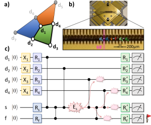
In this work, we employ a trapped ion quantum processor to demonstrate a flag-based FT weight-4 PCM scheme, which reduces the overhead for FT syndrome readout to two extra syndrome and flag qubits. The flag qubit detects hook errors, i.e. faults occurring on the syndrome qubit that proliferate onto two errors on the data qubit register. They would remain undetectable in a non-FT PCM scheme and eventually result in a logical error. In general, a weight-4 FT PCM circuit represents a key building block of the smallest distance-3 topological color code, which is equivalent to the Steane code Steane (1996); Bombin and Martin-Delgado (2006), as well as of FT circuit constructions for larger 2D topological QEC codes Chamberland and Beverland (2018); Tansuwannont et al. (2020); Lao and Almudever (2020). This stabilizer code Gottesman (1997) encodes logical qubit into physical qubits with a code distance and can therefore correct up to arbitrary error on any of the physical qubits, provided that QEC cycles are realized via fault-tolerant circuit constructions, based e.g. on the flag-qubit based FT PCM measurement demonstrated in this work. The physical qubits of the code can be arranged in a 2D triangular lattice structure formed by three interconnected 4-qubit plaquettes, as displayed in Fig. 1a. The set of parity check or stabilizer generators of the code generate the stabilizer group and are 4-qubit Pauli operators defined on vertices of each its plaquettes :
| (1) |
with the Pauli matrices pertaining to qubit . The code space hosting the logical qubit is fixed as the common two-dimensional eigenspace of eigenvalue of all generators (and combinations thereof),
| (2) |
Here, we focus on the experimental verification of a flag-based FT weight-4 parity check, , according to the circuit shown in Fig. 1c. The parity check is equivalent, as it merely requires mapping the data qubits by local rotations to the basis before syndrome readout. Four entangling gates of type lead to a phase shift on the syndrome for odd parity of the four data qubits, which is detected upon readout. Two additional entangling gates between the syndrome and flag qubits serve for catching error events throughout the PCM, which would otherwise result in weight-2 errors on the data qubit register (see Fig. 1 c).
QEC is intimately linked to multipartite entanglement Preskill (1998); Bennett et al. (1996); Lidar and Brun (2013); Almheiri et al. (2015); Rodriguez-Blanco et al. (2021). There are several works that reveal explicit connections between QEC and the production of maximally entangled states and equivalently, between entanglement fidelities of the encoded states and the weight distribution of a code Scott (2004); Raissi et al. (2018); Shor and Laflamme (1997); Rains (1998). The inherent relation of non-classical correlations as a prerequisite for QEC renders the generation and verification of genuinely multipartite entangled (GME) states to be a suitable benchmarking protocol for FT QEC building blocks. Here, we verify GME between the data and ancilla qubits in order to demonstrate the correct functioning of our FT PCM, and to benchmark the capabilities of our trapped-ion processor in the context of FT QEC.
II Shuttling-Based Trapped-Ion Platform
Quantum computer platforms based on trapped atomic ions arranged as static linear registers and laser addressing have seen substantial progress Monz et al. (2011); Debnath et al. (2016); Linke et al. (2017b). On such platforms, QEC building blocks have been demonstrated, such as repeated syndrome extraction and correction Schindler et al. (2011b); Negnevitsky et al. (2018), encoding, readout and gate operations for the code Nigg et al. (2014b), and entanglement of encoded logical qubits Erhard et al. (2021). However, QEC protocols impose stringent demands on the scalability of the underlying hardware platform. The shuttling-based “Quantum-CCD” approach offers a route to increased scalability Kielpinski et al. (2002); Lekitsch et al. (2017); Kaushal et al. (2020); Pino et al. (2021). Here, the qubit ions are kept in the form of small subsets within a microstructured trap array, and the register is dynamically reconfigured via shuttling operations. This way, the excellent degree of control can be retained for increasing register sizes. In this work, we implement a shuttling-based FT PCM protocol. Between subsequent gate operations on two qubits, the register is reconfigured via shuttling operations. A special feature of our protocol is that we establish the required effective all-to-all connectivity by reordering the register via physical rotation of two commonly confined ions. This operation is equivalent to a unit-fidelity SWAP logic gate Kaufmann et al. (2017a) and contrasts with faulty radiation-driven SWAP gates. This, together with the inherently low cross-talk of the shuttling-based architecture, allows to maintain the one-fault QEC condition.
We employ a micro-structured, segmented radio frequency ion trap Kaushal et al. (2020), consisting of 32 uniform segment pairs which are linearly arranged along a trap axis. Each segment pair can generate a confining potential well. All qubit operations - initialization, gates and readout - are carried out using laser beams, which are directed to segment 19 - henceforth referred to as laser interaction zone (LIZ). Shuttling operations are carried out by supplying suitable voltage waveforms to the trap electrodes. Potential wells containing one or two qubits can be moved along the trap axis Walther et al. (2012); Bowler et al. (2012), two commonly confined ions can be separated into potential wells Ruster et al. (2014); Kaufmann et al. (2014), two separately confined ions can be merged into one well, and two commonly confined ions can be rotated such that their ordering along the trap axis is reversed Kaufmann et al. (2017a). The separate / merge and swap shuttling operations are limited to the LIZ.
The qubits are encoded in the spin of the valence electron of atomic 40Ca+ ions Poschinger et al. (2009); Ruster et al. (2016), with the assignment . Gate operations are driven by a pair of beams detuned by about THz from the electric dipole transition. Local qubit rotations are realized via stimulated Raman transitions, allowing for arbitrary local rotations on qubit of the form
| (3) |
Local rotations can also be carried out simultaneously on two qubit ions commonly confined in the LIZ, in which case the Pauli operators are to be replaced by the respective tensor sum operators. Entangling gates between any two qubits and are realized via spin-dependent optical dipole forces Leibfried et al. (2003), effecting a phase shift between even and odd parity (with respect to the basis) states, represented by the unitary
| (4) |
We employ a maximally entangling gate with total phase , accumulated from two separate gate pulses, interspersed by a rephasing pulse. This leads to the total gate unitary
| (5) |
The rephasing pulses serve to maintain coherence Biercuk et al. (2009), especially on the syndrome and flag qubits, which undergo multiple entangling gates. Upon gate operations, the potential well in the LIZ features single-ion secular frequencies of MHz, with the lowest frequency pertaining to the trap axis. Entangling gates are carried out using the transverse in-phase collective vibrational mode at MHz as the gate-mediating mode. The laser beam geometry is chosen such that the gate operations are insensitive to the collective modes oscillating along the trap axis, which accumulate excitation from shuttling operations Kaufmann et al. (2017b).
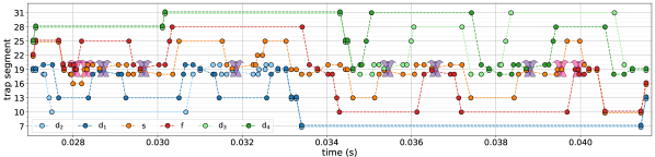
The shuttling schedule realizing the FT PCM is constructed from the primitive operations described above, such that the total count of shuttling operations and the maximum spatial extent of the register is minimized, while additional constraints such as the minimum number of empty trap segments between two qubit sets are always fulfilled. Initially, the qubits are stored pairwise in order and . The ion pairs are sequentially moved to the LIZ, where all four transverse modes are cooled close to the ground state via resolved-sideband cooling Poschinger et al. (2009), and the qubits are initialized to via optical pumping. Then, the data qubit sets are moved to the LIZ, where they are separated. Each data qubit is again moved into the LIZ, where optional -flips allow for preparation of any desired logical basis state. A similar procedure is then carried out for the syndrome and flag qubits, which are prepared in superposition states via rotations. Then, the parity mapping sequence is carried out: the qubits undergo pairwise entangling gates according to Eq. (5) in the sequence . Before and after each gate, an optional rotation can be carried out on the participating data qubit in order to change the basis. Between two consecutive gates, a sequence of movement, separate / merge and position-swap operations is carried out, bringing the qubit pair on which the following gate operation is to be carried out to the LIZ, see Fig. 2. Upon completion of the gate sequence, the syndrome and qubits are separately moved to the LIZ and each undergo an analysis rotation. Qubit phases accumulated from positioning in the inhomogeneous magnetic field have been calibrated via previous Ramsey-type measurements Walther et al. (2012); Ruster et al. (2017) and are corrected for. Upon completion of the gate sequence, the qubits are kept pairwise in order and . These pairs are sequentially moved to the LIZ in reverse order, where laser-driven population transfer from to the metastable state takes place. Then, the qubits are singled at the LIZ, where state-dependent laser-induced fluorescence is detected. Thresholding the number of detected photons allows for assigning detection events to logical () basis states, and equivalently to eigenvalues of the Pauli operator of qubit :
| (6) |
Logical results on rotated bases () are acquired by performing an analysis rotation () on the respective qubit before shelving and fluorescence detection. As the population transfer on all qubits is carried out before fluorescence detection, cross-talk errors throughout readout are avoided. Details on qubit and shuttling operations and the sequences for register preparation and readout can be found in the supplemental material sup .
III Measurement Results
III.1 Parity readout in the logical basis
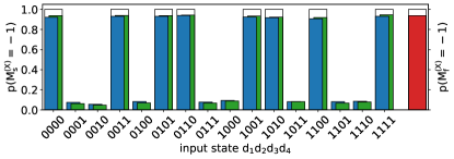
We first verify the functionality of the FT PCM protocol by carrying out the sequence shown in Fig. 2, while preparing the data qubits in all 16 computational basis states. Syndrome and flag qubit are initialized to by means of an rotation on the initial state . The measurement results of the syndrome are compared to the parity of the input state. We define the parity fidelity as
| (7) | |||||
i.e. the probability for the correct syndrome readout result conditioned on the input parity of the data qubits. For 960 shots per input state, we measure 92.3(2)%, see Fig. 3. For 93.7(2)% of all shots, the flag qubit is detected as , indicating a low rate of weight-2 errors. Post-selecting the syndrome measurement on the flag readout, we obtain a conditional parity fidelity of 93.2(2)%. It exceeds the bare parity fidelity by 4.5 standard errors, thus showing that the FT scheme operates in the regime where it can catch native errors occurring throughout the PCM sequence. A discussion on the relevant error sources can be found in the supplemental material sup .
| 1 | GME state | ||
|---|---|---|---|
| 2 | Substate | ||
| 3 | Substate | ||
| 4 | Stabilizer generator set | ||
| 5 | Witness operator | ||
| 6 | Bound | 3/4 | 5/6 |
III.2 Error Injection
In order to explicitly demonstrate that the FT PCM scheme can reliably detect hook errors, we deliberately inject errors or on the syndrome qubit (equivalence up to a global phase), between gates and , see Fig. 1. The resulting event rates for syndrome and flag are shown in Fig. 4. The injected , which corresponds to the simultaneous occurrence of a bit and a phase flip error, does not commute with the subsequent entangling gates Eq. 5. The three subsequent entangling gates involving the syndrome qubit lead to a final error, which is not detected upon syndrome measurement. It also proliferates to the data qubits in the form of and errors and would therefore compromise the encoded state. However, as it propagates to the flag as a error via entangling gate , it can still be detected. We observe an error detection rate of 90.6(6)% events on the flag. The syndrome still corresponds to the logical input state’s parity with 88.3(7)%. By contrast, the injected error results in a final error, such that the final syndrome events anti-correlate with the input parity, yielding 14.7(7)%. Thus, as expected, the injected error results in a PCM measurement error. Similarly to the error, an error detection rate of 89.7(6)% events is observed on the flag qubit. The latter indicates that the flag qubit again reliably detects the propagation of potentially detrimental weight-2 errors onto the data qubits, as is required to preserve the fault-tolerance of the scheme.
III.3 Generation of Genuine Multipartite Entanglement
The PCM scheme can be used to generate maximally entangled states. We verify four-qubit GME involving only the data qubits and extend it to the case of six-qubit GME, including the syndrome and flag qubits. The verification of -qubit GME is carried out efficiently via measurement of witness operators Guehne and Toth (2009); Bourennane et al. (2004), as the measurement overhead for complete state tomography Roos et al. (2004) would scale detrimentally with .
In contrast to the measurements discussed before, now all data qubits are initialized in via local rotations applied to . The GME states generated by the PCM are listed in Table 1 (lines 1-3). The GME states are verified via entanglement witnessing Guehne and Toth (2009); Friis et al. (2019). An entanglement witness is an observable whose expectation value is by construction positive or equal to zero for all separable states, , and negative for specific entangled states, . The four- and six-qubit output states of the PCM circuit belong to the class of stabilizer states, for which we use entanglement witness operators of the form
| (8) |
with the constant . These witnesses correspond – up to a normalization factor – to the witnesses proposed in Refs. Tóth and Gühne (2005a, b). They can be efficiently evaluated as they require the measurement of only the stabilizer generators (see Table 1, line 4). The expected ideal output states can be uniquely defined as eigenstates of the stabilizer generators with eigenvalue :
| (9) |
Thus, GME in the experimentally prepared -qubit states is signalled by a negative witness expectation value, , which is the case if the sum of generator expectation values exceeds the threshold value of , amounting to thresholds of and for the verification of four- and six-qubit GME, respectively. Each generator expectation value is determined by measuring the qubit register in a measurement setting where each qubit is subjected to appropriate analysis pulses before readout, which feature drive phases corrected for systematic phases acquired throughout the PCM sequence.
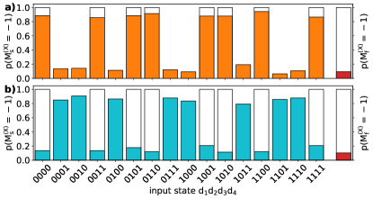
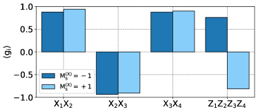
For preparation of a four-qubit GME state, the entangling gates between the syndrome and ancilla qubit are switched off, however the respective rephasing pulses are retained. The measured expectation values of the four stabilizer generators defined on the data qubits are shown in Fig. 5, each conditioned on the syndrome measurement result . Consistently with the four-qubit GME state in Table 1, () display even (odd) parity, respectively. The parity of depends conditionally on the syndrome readout result , as upon syndrome readout, the four data qubits are projected into the respective eigenspace of the measured parity check operator. For the input product state of the data qubits, they are projected into one of two four-qubit GHZ-type states. As the substates of the data qubits forming the GME state feature opposite parities in the basis, this shows that the PCM circuit reliably measures the parity in this basis upon initial basis change of the data qubits. Evaluating the entanglement witness expectation value conditionally on the syndrome measurement result, we obtain for and for , respectively. Both values fall below zero by more than 10 standard errors, we therefore certify conditional four-qubit GME.
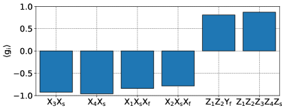
For the generation of six-qubit GME, we introduce additional rotations on the syndrome qubit, , between the and entangling gates Rodriguez-Blanco et al. (2021) and directly before the analysis rotation. Note that the first of these rotations on the syndrome qubit can be interpreted in the QEC context as a coherent rotation error, which propagates through the subsequent gates and results in a six-qubit equal-weighted coherent superposition state. Here, the first component corresponds to state where the error has propagated into two data qubit errors, captured by the flag-qubit (in ), and the second corresponds to the fault-free component (in ). The measured stabilizer expectation values are shown in Fig. 6, from which we compute the expectation value of the witness (see Table 1, line 5), obtaining . Falling below zero by 3.8 standard errors, we certify the capability of the flag-based PCM circuit to generate a six-qubit GME state.
IV Discussion and Outlook
We have successfully demonstrated a low qubit-overhead FT PCM scheme on a shuttling-based trapped-ion quantum processor. To that end, we have verified a parity measurement with high single-shot fidelity, that increases when taking the flag ancilla into account. By introducing errors deliberately, we have shown that the flag ancilla reliably detects the occurrence of errors, which would otherwise proliferate into uncorrectable weight-2 errors on the data qubit register. This verifies the FT operation of the PCM as key building block for QEC protocols. Furthermore, we have efficiently and holistically benchmarked the proper operation of the FT PCM scheme by witnessing four- and six-qubit GME generation for suitable input states. A key enabling feature of the FT PCM scheme is the virtually complete absence of crosstalk errors during gate operations. Beyond their relevance in the context of FT QEC, our results demonstrate the capability of realizing multi-qubit quantum protocols with effective all-to-all connectivity on a shuttling-based quantum processor architecture.
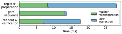
The timing budget of the protocol is shown in Fig. 7. About 23% of the duty cycle pertains to the PCM gate sequence, while the remainder pertains to register initialization – mostly cooling – and fluorescence readout. Of the the actual PCM gate sequence, 5% of the execution time is given by laser-driven gate interactions, while 95% is consumed by shuttling operation overhead. While the preparation and readout overheads scale linearly with the register size, the shuttling overhead pertaining to the gate sequences can scale up to quadratically with the qubit number, depending on the connectivity required by the underlying protocol. This overhead can be mitigated by improving the control hardware to decrease the time required for qubit register reconfigurations, but also by using multiple manipulation sites for parallel processing Mehta et al. (2020). We have carried out a circuit of moderate depth without the requirement of in-sequence cooling for removing excitation of vibrational modes of the ions incurred from the shuttling operations. Future extensions will include dual-species operation for sympathetic cooling for further increase of sequence depths, and for non-destructive in-sequence readout Ballance et al. (2015); Tan et al. (2015). These improvements will pave the way for using the FT PCM demonstrated here as a building block for FT QEC cycles executed on complete logical qubits Bermudez et al. (2017, 2019).
Acknowledgements.
We acknowledge former contributions of Thomas Ruster, Henning Kaufmann and Christian Schmiegelow to the experimental apparatus. The research is based upon work supported by the Office of the Director of National Intelligence (ODNI), Intelligence Advanced Research Projects Activity (IARPA), via the U.S. Army Research Office grant W911NF-16-1-0070. The views and conclusions contained herein are those of the authors and should not be interpreted as necessarily representing the official policies or endorsements, either expressed or implied, of the ODNI, IARPA, or the U.S. Government. The U.S. Government is authorized to reproduce and distribute reprints for Governmental purposes notwithstanding any copyright annotation thereon. Any opinions, findings, and conclusions or recommendations expressed in this material are those of the author(s) and do not necessarily reflect the view of the U.S. Army Research Office. We gratefully acknowledge funding from the EUH2020-FETFLAG-2018-03 under Grant Agreement no.820495, the European Research Council (ERC) via ERC StG QNets Grant Number 804247, and by the Germany ministry of science and education (BMBF) via the VDI within the projects VERTICONS and IQuAn.References
- Nielsen and Chuang (2000) M. A. Nielsen and I. L. Chuang, Quantum Computation and Quantum Information (Cambridge University Press, 2000).
- Montanaro (2016) A. Montanaro, npj Quantum Information 2, 15023 (2016).
- Arute et al. (2019) F. Arute et al., Nature 574, 505 (2019).
- Alexeev et al. (2021) Y. Alexeev et al., PRX Quantum 2, 017001 (2021).
- Terhal (2015) B. M. Terhal, Reviews of Modern Physics 87, 307 (2015).
- Hume et al. (2007) D. B. Hume, T. Rosenband, and D. J. Wineland, Phys. Rev. Lett. 99, 120502 (2007).
- Lupaşcu et al. (2007) A. Lupaşcu et al., Nature Physics 3, 119 (2007).
- Barreiro et al. (2011) J. T. Barreiro et al., Nature 470, 486 (2011).
- Córcoles et al. (2015) A. D. Córcoles et al., Nature Communications 6, 6979 (2015).
- Devitt et al. (2013) S. J. Devitt, W. J. Munro, and K. Nemoto, Reports on Progress in Physics 76, 076001 (2013).
- Preskill (1996) J. Preskill, “Fault-tolerant quantum computation,” in Introduction to Quantum Computation and Information (1996) p. 213.
- DiVincenzo and Shor (1996) D. P. DiVincenzo and P. W. Shor, Phys. Rev. Lett. 77, 3260 (1996).
- DiVincenzo and Aliferis (2007) D. P. DiVincenzo and P. Aliferis, Phys. Rev. Lett. 98, 020501 (2007).
- Chao and Reichardt (2018) R. Chao and B. W. Reichardt, Phys. Rev. Lett. 121, 050502 (2018).
- Chamberland and Beverland (2018) C. Chamberland and M. E. Beverland, Quantum 2, 53 (2018).
- Chamberland and Cross (2019) C. Chamberland and A. W. Cross, Quantum 3, 143 (2019).
- Bermudez et al. (2019) A. Bermudez, X. Xu, M. Gutiérrez, S. C. Benjamin, and M. Müller, Phys. Rev. A 100, 062307 (2019).
- Reichardt (2020) B. W. Reichardt, Quantum Science and Technology 6, 015007 (2020).
- Tansuwannont et al. (2020) T. Tansuwannont, C. Chamberland, and D. Leung, Phys. Rev. A 101, 012342 (2020).
- Chamberland et al. (2020) C. Chamberland, A. Kubica, T. J. Yoder, and G. Zhu, New Journal of Physics 22, 023019 (2020).
- Chao and Reichardt (2020) R. Chao and B. W. Reichardt, PRX Quantum 1, 010302 (2020).
- Nigg et al. (2014a) D. Nigg et al., Science 345, 302 (2014a).
- Müller et al. (2016) M. Müller et al., Phys. Rev. X 6, 031030 (2016).
- Schindler et al. (2011a) P. Schindler et al., Science 332, 1059 (2011a).
- Kielpinski et al. (2001) D. Kielpinski et al., Quantum Info. Comput. 1, 113 (2001).
- Chiaverini et al. (2004) J. Chiaverini et al., Nature 432, 602 (2004).
- Negnevitsky et al. (2018) V. Negnevitsky et al., Nature 563, 527 (2018).
- Stricker et al. (2020) R. Stricker et al., Nature 585, 207 (2020).
- Kelly et al. (2015) J. Kelly et al., Nature 519, 66 (2015).
- Ofek et al. (2016) N. Ofek et al., Nature 536, 441 (2016).
- Andersen et al. (2020) C. K. Andersen et al., Nature Physics 16, 875 (2020).
- Chen et al. (2021) Z. Chen et al., “Exponential suppression of bit or phase flip errors with repetitive error correction,” (2021), arXiv:2102.06132 [quant-ph] .
- Zhang et al. (2012) J. Zhang, R. Laflamme, and D. Suter, Phys. Rev. Lett. 109, 100503 (2012).
- Knill et al. (2001) E. Knill, R. Laflamme, R. Martinez, and C. Negrevergne, Phys. Rev. Lett. 86, 5811 (2001).
- Waldherr et al. (2014) G. Waldherr et al., Nature 506, 204 (2014).
- Unden et al. (2016) T. Unden et al., Physical Review Letters 116, 230502 (2016).
- Srinivas et al. (2021) R. Srinivas et al., “High-fidelity laser-free universal control of two trapped ion qubits,” (2021), arXiv:2102.12533 [quant-ph] .
- Clark et al. (2021) C. R. Clark et al., “High-fidelity bell-state preparation with \ce^40Ca+ optical qubits,” (2021), arXiv:2105.05828 [quant-ph] .
- Kjaergaard et al. (2020) M. Kjaergaard et al., “Programming a quantum computer with quantum instructions,” (2020), arXiv:2001.08838 [quant-ph] .
- Browaeys and Lahaye (2020) A. Browaeys and T. Lahaye, Nature Physics 16, 132 (2020).
- Raussendorf and Harrington (2007) R. Raussendorf and J. Harrington, Phys. Rev. Lett. 98, 190504 (2007).
- Takita et al. (2017) M. Takita, A. W. Cross, A. D. Córcoles, J. M. Chow, and J. M. Gambetta, Phys. Rev. Lett. 119, 180501 (2017).
- Linke et al. (2017a) N. M. Linke et al., Science Advances 3 (2017a).
- Egan et al. (2021) L. Egan et al., “Fault-tolerant operation of a quantum error-correction code,” (2021), arXiv:2009.11482 [quant-ph] .
- Steane (1996) A. M. Steane, Phys. Rev. Lett. 77, 793 (1996).
- Bombin and Martin-Delgado (2006) H. Bombin and M. A. Martin-Delgado, Phys. Rev. Lett. 97, 180501 (2006).
- Lao and Almudever (2020) L. Lao and C. G. Almudever, Phys. Rev. A 101, 032333 (2020).
- Gottesman (1997) D. Gottesman, Ph.D. thesis, arXiv:9705052(1997) (1997).
- Preskill (1998) J. Preskill, Lecture notes for Physics 219: Quantum Computation (California Institute of Technology, Pasadena, CA, 1998).
- Bennett et al. (1996) C. H. Bennett, D. P. DiVincenzo, J. A. Smolin, and W. K. Wootters, Phys. Rev. A 54, 3824 (1996).
- Lidar and Brun (2013) D. A. Lidar and T. A. Brun, Quantum Error Correction (Cambridge University Press, United Kingdom, 2013).
- Almheiri et al. (2015) A. Almheiri, X. Dong, and D. Harlow, Journal of High Energy Physics 2015, 163 (2015).
- Rodriguez-Blanco et al. (2021) A. Rodriguez-Blanco, A. Bermudez, M. Müller, and F. Shahandeh, PRX Quantum 2, 020304 (2021).
- Scott (2004) A. J. Scott, Phys. Rev. A 69, 052330 (2004).
- Raissi et al. (2018) Z. Raissi, C. Gogolin, A. Riera, and A. Acín, Journal of Physics A: Mathematical and Theoretical 51, 075301 (2018).
- Shor and Laflamme (1997) P. Shor and R. Laflamme, Phys. Rev. Lett. 78, 1600 (1997).
- Rains (1998) E. Rains, IEEE Transactions on Information Theory 44, 1388 (1998).
- Monz et al. (2011) T. Monz et al., Phys. Rev. Lett. 106, 130506 (2011).
- Debnath et al. (2016) S. Debnath et al., Nature 536, 63 (2016).
- Linke et al. (2017b) N. M. Linke et al., Proceedings of the National Academy of Sciences 114, 3305 (2017b).
- Schindler et al. (2011b) P. Schindler et al., Science 332, 1059 (2011b).
- Nigg et al. (2014b) D. Nigg et al., Science 345, 302 (2014b).
- Erhard et al. (2021) A. Erhard et al., Nature 589, 220 (2021).
- Kielpinski et al. (2002) D. Kielpinski, C. Monroe, and D. J. Wineland, Nature 417, 709 (2002).
- Lekitsch et al. (2017) B. Lekitsch et al., Science Advances 3 (2017).
- Kaushal et al. (2020) V. Kaushal et al., AVS Quantum Science 2, 014101 (2020).
- Pino et al. (2021) J. M. Pino et al., Nature 592, 209 (2021).
- Kaufmann et al. (2017a) H. Kaufmann et al., Phys. Rev. A 95, 052319 (2017a).
- Walther et al. (2012) A. Walther et al., Phys. Rev. Lett. 109, 080501 (2012).
- Bowler et al. (2012) R. Bowler et al., Phys. Rev. Lett. 109, 080502 (2012).
- Ruster et al. (2014) T. Ruster et al., Phys. Rev. A 90, 033410 (2014).
- Kaufmann et al. (2014) H. Kaufmann, T. Ruster, C. T. Schmiegelow, F. Schmidt-Kaler, and U. G. Poschinger, New Journal of Physics 16, 073012 (2014).
- Poschinger et al. (2009) U. G. Poschinger et al., Journal of Physics B: Atomic, Molecular and Optical Physics 42, 154013 (2009).
- Ruster et al. (2016) T. Ruster et al., Applied Physics B 122, 254 (2016).
- Leibfried et al. (2003) D. Leibfried et al., Nature 422, 412 (2003).
- Biercuk et al. (2009) M. J. Biercuk et al., Nature 458, 996 (2009).
- Kaufmann et al. (2017b) H. Kaufmann et al., Phys. Rev. Lett. 119, 150503 (2017b).
- Ruster et al. (2017) T. Ruster et al., Phys. Rev. X 7, 031050 (2017).
- (79) See Supplemental Material at [URL will be inserted by publisher] for a detailed error discussion.
- Guehne and Toth (2009) O. Guehne and G. Toth, Physics Reports 474, 1 (2009).
- Bourennane et al. (2004) M. Bourennane et al., Phys. Rev. Lett. 92, 087902 (2004).
- Roos et al. (2004) C. Roos et al., Science 304, 1478 (2004).
- Friis et al. (2019) N. Friis, G. Vitagliano, M. Malik, and M. Huber, Nature Reviews Physics 1, 72 (2019).
- Tóth and Gühne (2005a) G. Tóth and O. Gühne, Phys. Rev. A 72, 022340 (2005a).
- Tóth and Gühne (2005b) G. Tóth and O. Gühne, Phys. Rev. Lett. 94, 060501 (2005b).
- Mehta et al. (2020) K. K. Mehta et al., Nature 586, 533 (2020).
- Ballance et al. (2015) C. J. Ballance et al., Nature 528, 384 (2015).
- Tan et al. (2015) T. R. Tan et al., Nature 528, 380 (2015).
- Bermudez et al. (2017) A. Bermudez et al., Phys. Rev. X 7, 041061 (2017).
See pages ,1,,2,,3,,4,,5 of ./figs/6QBFTRsupp.pdf