Exploration of trivial and non-trivial electronic phases and of collinear and non-collinear magnetic phases in low-spin d5 perovskites
Abstract
The and transition metal oxides have become important members of the emerging quantum materials family due to competition between onsite Coulomb repulsion () and spin-orbit coupling (SOC). Specifically, the systems with electronic configuration in an octahedral environment are found to be capable of posessing invariant semimetallic state and perturbations can lead to diverse magnetic phases. In this work, by formulating a multi-band Hubbard model and performing SOC tunable DFT+ calculations on a prototype SrIrO3 and extending the analysis to other iso-structural and isovalent compounds, we present eight possible electronic and magnetic configurations in the -SOC phase diagram that can be observed in the family of low-spin perovskites. They include the protected Dirac semimetal state, metal and insulator regimes, collinear and noncollinear spin ordering. The latter is explained through connecting hopping interactions to the rotation and tilting of the octahedra as observed in GdFeO3. Presence of several soft phase boundaries makes the family of perovskites an ideal platform to study electronic and magnetic phase transitions under external stimuli.
I Introduction
In the past decade the discovery that spin-orbit coupling leads to the formation of symmetry protected conducting surface or edge states in a wide range of topological class of compounds, has attracted a great deal of attention among the researchers working in quantum many-body theory Hasan and Kane (2010); Qi and Zhang (2011). The SOC is a relativistic effect and it is treated as a small perturbation in solids. But for systems with heavy elements, it varies as fourth power of the atomic number and therefore it has an intriguing influence on the electronic and magnetic structure of such systems. In the family of correlated oxide systems, where the onsite Coulomb repulsion with other competing interactions such as Hund’s coupling (), crystal field () and electron hopping strength () create a rich electronic and magnetic phase diagram, the presence of SOC bridges the symmetry protected topologically invariant states and magnetism. Moving down the periodic table from to to elements, while the SOC increases, the orbitals become more spatially extended to reduce the correlation strength . For the families of oxides, both SOC and becomes comparable and these two competing interactions give rise to emergent phenomena.
For the experimenters and theoreticians alike, the family of iridates, one of the oxide families, have become a test bed for exploring these emergent phenomena that includes topological Mott insulator Pesin and Balents (2010), fractional Chern insulator Bergholtz and Liu (2013), Kitaev’s celebrated spin liquid phase Baskaran et al. (2007); Takagi et al. (2019); Okamoto et al. (2007), Dirac and Weyl semimetals Yan and Felser (2017); Vafek and Vishwanath (2014), Axion insulator Wan et al. (2012), and high- superconductivity. For example, pyrochlore iridates exhibit topological semimetal and Mott insulating phases Wan et al. (2011); Witczak-Krempa et al. (2013); Topp et al. (2018). The honeycomb iridates host unconventional magnetic and spin liquid phases Rau et al. (2014); Chaloupka et al. (2013); Reuther et al. (2014); Takahashi et al. (2019); Kenney et al. (2019). The monolayer and bilayer Ruddlesden-Popper strontium iridates, Sr2IrO4 and Sr3Ir2O7, exhibits canted in-plane and collinear out-of-plane antiferromagnetic (AF) insulating state Nauman et al. (2017); Kim et al. (2008); Watanabe et al. (2013); Yan et al. (2015); Fujiyama et al. (2012).
Among the family of iridates, the orthorhomic pervoskite iridates with chemical formula AIrO3, constitutes a large class of anisotropic oxides with exceptionally wide range of properties. In these oxides the IrO6 octahedra is distorted as compared to the symmetric cubic structure. These class of oxides with Pbnm space group symmetry was proposed to realize a new class of metal dubbed topologically crystalline metal with flat surface state and phase transition to other non-trivial phases in the presence of external field has been theoretically proposed Chen et al. (2015). For example, SrIrO3 and CaIrO3 are paramagntic Dirac semimetals (DSM) Nie et al. (2015); Fujioka et al. (2017, 2019, 2021). Carter et al. Carter et al. (2012) showed that SrIrO3 undergoes a phase transition from semimetal to strong topological insulator by breaking the mirror symmetry. BaIrO3 is a Pauli paramagnetic metal (PM) with Fermi liquid ground state below 6 K Cheng et al. (2013). In comparison to the AIrO3, the other and perovskites with isolvalent configuration, where the SOC is weak and electron correlation is strong, have different electronic and magnetic phases in their ground state. For example, SrCoO3 and CaCoO3 exhibits high-spin (HS) ferromagnetic metal (FM) state whereas SrRhO3 and YRuO3 exhibits low-spin (LS) FM and canted antiferromagnetic insulator (CAFI) ground state Xia et al. (2017); Mathi Jaya et al. (1991); Singh (2003); Ji et al. (2020).
For the perovskites, due to strong octahedral crystal field the orbital degeneracy gets lifted giving rise to and manifold. In the presence of SOC the manifold splits into spin-orbital entangled pseudo-spin = 3/2 and = 1/2 states. In the case of a (Ir4+) configuration, the = 3/2 states are completely occupied and the ground state is constituted of the = 1/2 pseudo-spin. These narrow = 1/2 bands formed due to strong SOC are more susceptible to Mott localization by , due to reduced bandwidth, which implies that stronger the SOC is, weak critical () will be required to make a transition from metal to a spin-orbit coupled Mott insulator. By carrying out first-principles density functional theory (DFT) calculations within the framework of local density approximation (LDA)+ on the prototype system SrIrO3, Zeb et al. Zeb and Kee (2012) presented an electronic phase diagram in the -SOC configuration space, and broadly suggested three domains. These are magnetic metal in the weak to intermediate SOC and weak to high regime, nonmagnetic metal (NM) or DSM in the weak to intermediate and weak to high SOC regime, and magnetic insulator in the weak to high SOC and intermediate to high regime.
The aforementioned discussion on the electronic structure of orthorhombic perovskites suggest that a much more intricate phase diagram needs to be constructed for the family of oxides in the -SOC space in order to explore the emerging quantum phases in this family. Firstly, it needs to be revisited if in the absence of SOC, the system remains metallic even for very high . Secondly, in the absence of collinear spin-arrangement questions arise whether sub-domains with non-trivial quantum states exist within the four proposed broad domains. Thirdly, the role of structural distortions - from the isotropic cubic configuration to symmetry lowered orthorhombic configuration - needs to be examined in building the phase diagram as it is known to be a key player in driving the electronic and magnetic phase transitions in the perovskite family Torrance et al. (1992); García-Muñoz et al. (1992); Miyasaka et al. (2003); Zhou et al. (2005, 2010); Vogt et al. (2003); Kim et al. (2017); Liu et al. (2015).
In this work we have employed a multi-band Hubbard model which is solved self-consistently in the mean-field framework and validated the results with DFT+ calculations to establish a detailed phase diagram discovering the earlier unexplored sub-domains. The present study establishes the complex interplay among SOC, , and structural distortions to explain the formation of collinear and non-collinear magnetism as well as metallic, insulating, and non-trivial semiemtallic phases in the family of LS perovskites.
II Structural and Computational Details
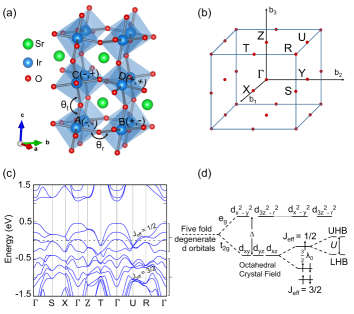
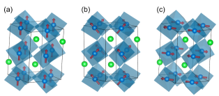
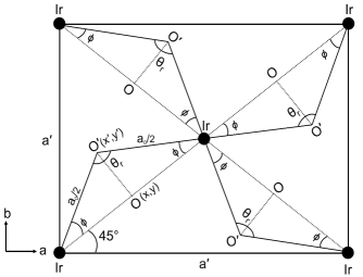
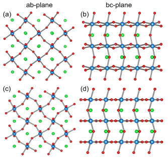
Bulk SrIrO3 crystallizes in an orthorhombic pervoskite crystal structure (space group Pbnm) with the GdFeO3-type lattice distortion as shown in Fig. 1(a). The IrO6 octahedra undergoes a staggered rotation about the axis by an angle = , followed by another rotation about the [110] direction by tilt angle = . Due to these tilt and rotations of the IrO6 octahedra, the unit cell gets doubled in the ab as well as in the ac plane due to supercell geometry where is the nearest-neighbour Ir-Ir distance. Hence, SrIrO3 contains four formula units per unit cell leading to four inequivalent Ir sublattices (A,B,C,D). The two signs on each Ir sublattice represents the sense of the rotation and tilting of the octahedra, clockwise (+) or anticlockwise (-). The experimental lattice parameters are = 5.56 Å, = 5.59 Å and = 7.88 Å Zhao et al. (2008).
In order to study the effect of correlation and SOC on the electronic and magnetic phases in bulk SrIrO3, we developed a multi-band Hubbard model and solved it self-consistently as discussed in Sec. IV and also carried out comprehensive DFT calculations in the -SOC space. The calculations are performed using plane-wave based projector augmented wave method (PAW) Kresse and Joubert (1999); Blöchl (1994) as implemented in Vienna ab-initio simulation package (VASP) Kresse and Furthmüller (1996) within the PerdewBurkeErnzerhof generalized gradient approximation (GGA) for exchange-correlation functional. In this study, the SOC is varied in units of , where is the real SOC strength (= 0.43 eV) as obtained from the SCF calculations to achieve the ground state. The Brillouin zone integrations are carried out using Monkhorost-Pack k-mesh which yields 256 k-points in the irreducible part of the Brilluion zone. The kinetic energy cutoff for plane-wave basis set was chosen to be eV. The strong correlation effect is incorporated via an effective onsite correlation parameter = through the rotationally invariant approach introduced by Dudarev Dudarev et al. (1998).
III Ground State Electronic Structure of SrIrO3
The ground state electronic structure, as shown in Fig. 1(c), implies that bulk SrIrO3 exhibits nonmagnetic semimetallic ground state with a Dirac node at the high symmetry point U. This is due to the combined effect of cubic asymmetry, octahedral crystal field and SOC towards the removal of degeneracy in the manifold as illustrated in Fig. 1(d). Due to strong octahedral crystal field, the five-fold degenerate states split into a higher-energy and unoccupied doublet and a lower-energy triplet. While the states are unaffected by the SOC, the manifold is further SOC split into a = 1/2 doublet ( = 1/2) and a = 3/2 ( = 3/2, 1/2) quartet, hence, forming three Kramer’s pair. The expressions are given by,
| (1) | ||||
| (2) | ||||
| (3) |
where corresponds to spin = /, respectively. With lowering in symmetry through and , two pairs of bands make linear crossing at the high symmetry point U to create double Dirac nodes resulting in a DSM phase. It has been reported that the two Dirac nodes may not be degenerate in energy and in that case the cones may penetrate to form a nodal ring Zeb and Kee (2012). Through our model Hamiltonian in the Sec. IV, we will attribute the formation of the DSM phase due to the development of - interaction in the next-nearest neighborhood due to tilting and rotation of octahedra. Besides the crystal field and SOC, the onsite Coulomb repulsion is also deterministic of the electronic structure of the (Ir4+) compounds. Four out of five electrons occupy the = 3/2 state, leaving one electron in the state (see Fig. 1(d)). The onsite repulsion further splits this degenerate state to create a lower Hubbard (LHB) and upper Hubbard (UHB) subband. However, experimental studies Longo et al. (1971); Nie et al. (2015); Fujioka et al. (2017) including ARPES measurements show that the SrIrO3 is a paramagnetic semimetal. This demonstrates that the competition between SOC and can lead to a plethora of electronic and magnetic phases for the perovskites.
Apart from the perovskite structure, several other iridates and iridate like systems with configuration and with similar octahedral complexes, exhibit wide range of magnetic phases with spin anisotropy Modic et al. (2014); Nauman et al. (2017); Boseggia et al. (2013); Chaloupka and Khaliullin (2016); Biffin et al. (2014); Reuther et al. (2014). Therefore, we utilize SrIrO3 as prototype to build a platform so that the emerging quantum phases in the -SOC configuration space can be envisaged and analyzed. The phase diagram will be discussed in detail in the Sec. V.
IV Multi-Band Hubbard Model
Across the iridates family, it has been shown that the competition between and influences the eigen states substantially. To get a flavour of it in the single pervoskite structure, we employ a mean-field based multi-band Hubbard model Hamiltonian to explore the non-trivial/trivial phases emerging in the weak/strong -SOC regime. To start with, we first consider tight binding (TB) model with SOC, where a minimal basis set formed by Ir- orbitals (,,,,) has been considered. The five orbital basis set, instead of based three orbital, introduces - intermixing due to finite and in the distorted frame leading to significant altering of the band structure.
To extract the nearest-neighbour (NN), next-nearest-neighbour (NNN) and hopping interactions and SOC strength, a TB model for undistorted SrIrO3 is formulated and then using these parameters and transforming the hopping matrices in the rotated basis (as explained in Appendix A), the effect of distortion on the electronic and magnetic properties has been examined. In the second quantization notation, the TB + SOC component of the Hamiltonian is given by,
| (4) | |||||
Here, i(j), () are site and orbital indices, respectively. The parameters and represents the onsite energy and strength of hopping integrals, respectively. The SOC is added in the third term of the Hamiltonian with denoting its strength. In compact form, for a single formula unit as is the case with cubic perovskite structure, H is given by
| (5) |
Here, H↑↑ = H↓↓ and H↑↓ = (H to ensure the time reversal (TR) invariance of the Hamiltonian. For the four formula unit () supercell, which build the primitive unit cell of the orthorhombioc phase, the augmented Hamiltonian representing four-Ir (A,B,C,D) sublattices then takes the shape of
| (6) |
The TB component built with Slater-Koster formalism Slater and Koster (1954) is further elaborated in the Appendix A.
For the distorted case, with finite and , as defined through Fig. 1(a), the hopping matrices are obtained by using the following transformation
| (7) |
where R is the transformation matrix and can be calculated using rotation matrix for the cubic harmonics (L = 2) (Eq. A3 of Appendix A). For the rotation and tilting, as appropriate for SrIrO3, it is respectively defined as
| (8) |
| (9) |
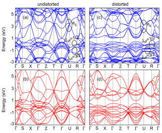
The values of onsite energy (), hopping strength () and SOC strength () are obtained by fitting the TB+SOC bands with the DFT+SOC bands for the undistorted case as shown in Figs. 2 (a,b). The fitted values are listed in Table 1. TB bands, as shown in Fig. 2, captures very well the essential features of the DFT band structure. In this LS () configuration, while the overlapping of the and bands is prominent in the undistorted frame (Figs. 2(a,b)), they are very well segregated in the distorted frame (Fig. 2(c)) and this is very well captured in our TB model (Fig. 2(d)). The distortion also introduces a DSM phase as linear bands cross each other at the high symmetry point U in the vicinity of the Fermi energy ().
| -0.79 | 2.4 | -0.38 | -0.13 | 0.04 | -0.85 | -0.5 | 0.1 | 0.04 | 0.43 |
Having formulated the kinetic part of the Hamiltonian, we now consider the interacting part of the Hamiltonian () which is described in terms of the multi-orbital Hubbard-Kanamori formalism Luo (2013).
| (10) |
Here, the first two terms gives the energy cost of having the electrons in the same or different orbitals at the same lattice site. The third term defines the Hund’s rule coupling that favours the ferromagnetic alignment of spins in the orbitals at the same lattice site. The relation = - between the Kanamori parameters Kanamori (1963) has been used here.
In the Hartree approximation, , , and can be decoupled as
| (11) |
| (12) |
| (13) |
where, = + , is the total charge density of orbital at site i.
Hence, the total Hamiltonian is given by
| (14) |
It is solved self-consistently in the momentum space by employing Hartree approximation as described above. The -SOC space give rise to different magnetic phases, as shown in Fig. 3, beyond the semimetallic nonmagnetic phase. We set / = 0.2 as relevant for oxides Meetei2015 and = as the energy scale unit. For = 0, a FM phase (see Fig. 3(a)), with highly dispersive bands (higher mobility) stabilizes. For even higher values, a FM state remains stable for the undistorted case.
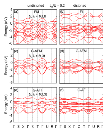
With SOC, the system shows intriguing magnetic phases where the = 1/2 states determine the ground state. For lower values, a weak G-type antiferromagnetic metal (G-AFM) state (Fig. 3(c)) with broken Dirac node forms the ground state. It is due to breaking of the TR symmetry. Here, the SOC induces the spin degeneracy and strengthen the localization and hence decreases the mobility. The weak G-AFM state has small hole and electron pockets which disappears on further increasing and a gap is opened in the = 1/2 spectrum to stabilize a G-type antiferromagnetic insulator (G-AFI) phase (Fig. 3(e)). Finite distortion induces anisotropy in the orbital () occupancies with onsite Coulomb repulsion enhances the spin split and drives the system to a ferromagnetic insulator (FI) phase (Fig. 3(b)). Hence, competition between , SOC and structural distortion alters the magnetic and electronic phase of the system substantially. Recent studies on iridates and their superlattices emphasize the crucial role of distortion induced anisotropic spin interactions leading to non-collinear magnetic phases Mohapatra et al. (2019); Kim et al. (2017); Liu et al. (2015). However, the current model is based on collinear magnetism and therefore cannot predict non-collinear phases due to the absence of exchange terms in the Hamiltonian. Therefore, we carried out pseudopotential based DFT calculations to explore the novel electronic and magnetic states in the -SOC domain and build the quantum phase diagram of pervoskites in the LS state by taking SrIrO3 as a prototype.
V DFT++SOC Electronic Structure
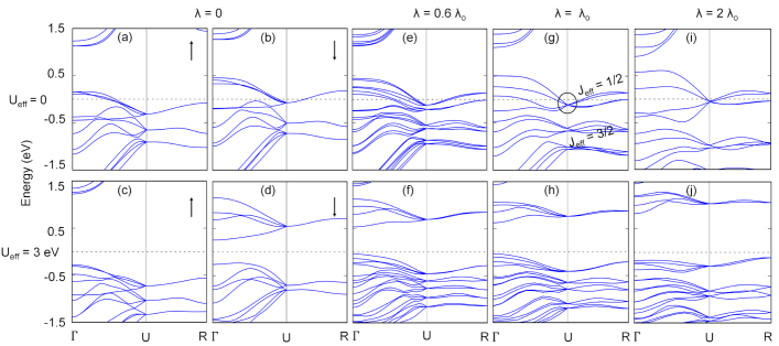
Through Fig. 4, we will analyze the electronic structure evolution as a function of and SOC. In the ground state, we estimated the SOC strength to be 0.43 eV by measuring the split between = 1/2 and = 3/2 states which is equal to 3/2 (see Fig. 1(d)). In order to examine the role of , we scaled it in units of . For = = 0, it is pure octahedral crystal field effect where the orbitals split into lower-lying and partially occupied three-fold degenerate and upper-lying two-fold degenerate states as shown in Fig. 4(a,b). Due to imbalance in the population of the states in two different spin channels the system becomes a Stoner ferromagnet. As increases, real spin states of the manifold evolve and give rise to pseudo-spin states with the formation of spin-orbit entangled = 1/2 states lying in the vicinity of the and = 3/2 states lying below in the valence band. For weak , the four = 1/2 pairs, corresponding to the four-Ir sublattices, create two set of four-fold degenerate bands along the k-path U-R. These two sets merge at the high symmetry point U with increasing SOC to form a DSM phase (see Figs. 4(e,g,i)).
With increasing correlation effect, say for = 3 eV and no SOC, as shown in Figs. 4(c,d), the onsite repulsion n↑n↓ increases the spin split to form a gap which in turn makes the system a FI. This phase is very well captured by the model Hamiltonian described in the previous section. As SOC competes with , Figs. 4(f,h,j), the four = 1/2 pairs create lower and upper Hubbard subbands, which breaks the Dirac node to form a gap and concurrently stabilizes the system in a CAFI state. The band gap rises from 0.23 eV at / to 0.93 eV at / = 2, manifesting the amplified effect of correlations as the SOC strength increases. The spin anisotropy and the overall phases predicted in the -SOC domain will be elaborated further in the next subsection.
BULK PHASE DIAGRAM
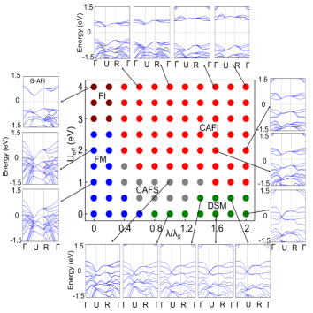
The phase diagram for the orthorhombic SrIrO3 spanned in -SOC space, as evaluated from the DFT++SOC calculations is presented in Fig. 5. It shows five distinct phases: (i) collinear FM as shown in blue, (ii) collinear FI as shown in maroon, (iii) canted antiferromagnetic semimetal (CAFS) as shown in grey, (iv) CAFI as shown in red, and (v) DSM as shown in green. Let us first examine the weak SOC regime (/ 0.2). Up to eV, the system remains a FM with collinear magnetic ordering as shown in Fig. 6(a).
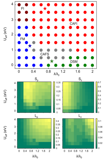
This results from the imbalance of the population of partially occupied states in the up-spin and down-spin channels as already explained through Figs. 4(a,b) in the previous subsection. With further increase in , the system undergoes a transition from FM to FI because of the fact that with enhanced spin split the earlier partially occupied band in the up-spin channel is now occupied completely whereas in the down spin channel it becomes empty (see Fig. 4(c,d)). The FI phase, as predicted from our model and DFT calculations, was not captured in the earlier study Zeb and Kee (2012) where the stability of the metallic phase for all in the non-SOC regime was reported. It may be noted that the authors there have carried out the calculations using the full-potential linearized augmented-plane-wave (LAPW) method with LDA exchange-correlation functional. The strength of local magnetic moment at Ir depends on . It increases from at = eV to at = eV. With the LS state, the saturated magnetic moment is 1 which can be realized for further higher value of . The LS state favours the ferromagnetic order over the antiferrromagnetic one.
With finite , the up-spin and down-spin states mix to form spin-orbit entangled pseudo-spin = 1/2 and = 3/2 states. The former occupy the and hence determine the electronic and magnetic phase of the system. For the intermediate range (0.4 / 1.4), the lower value of maintains the metallicity and at the same time weakens the magnetic state with the formation of a DSM phase. It is important to note that the electron hopping, SOC and onsite Coulomb repulsion are in the same energy scale and hence any perturbation can give rise to a different quantum phase. Here, we show that even weak transforms the DSM to CAFS phase suggesting this weakly correlated perovskite is near to the magnetic instability. The onsite Coulomb repulsion facilitate the non-collinear ordering of the spin-orbit entangled states as the planar-spin () component increase in magnitude in proportion to / which can be observed from the spin-intensity map shown in the middle panel of Fig. 5. The onsite repulsion also strengthens the localization to stabilize the CAFI phase as can be seen from the phase diagram.
For the large / regime (/ 1.4), the system exhibits either DSM for low or CAFI phase for lower and higher values. In the latter case, the component gradually vanishes with SOC (see Fig. 5 middle panel) to create a transition from the collinear along to non-coplanar and canted to pure co-planar spin arrangement. This transition is schematically illustrated in Fig. 6. Earlier studies have presented an unusual trend where it has been suggested that higher value of is required to induce metal-to-insulator transition for the higher value of SOC Zeb and Kee (2012). However, as expected, in this study we observe that a lower value is sufficient to stabilize a CAFI phase.
The 4 pervoskites SrRhO3, LaRuO3 and YRuO3 and the perovskites are reported to be having LS electonic configuration and all of them undergo GdFeO3-type distortion of varied order. Their electronic and magnetic phases can be mapped to the phase diagram of Fig. 5. The compounds SrRhO3 Singh (2003) and LaRuO3 Kobayashi et al. (1994), with weak SOC and moderate correlation exhibits FM ground state and can be placed in the region (0.2 / 0.4, 1 2 eV). The compound YRuO3 Ji et al. (2020) exhibits CAFI phase and lies in (0.6 / 0.8, 3 4 eV) zone. Like SrIrO3, CaIrO3 Fujioka et al. (2019) stabilizes in nonmagnetic DSM phase and lies in (0.8 / 1, 0 0.5 eV) zone of the phase diagram. In Appendix C, we have compared the phase diagrams of SrIrO3 and CaIrO3 (see Fig. 11) to demonstrate the generality of the electronic structure evolving out of competition between electron-electron correlation and SOC.
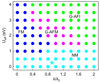
To identify the divison of role between SOC and structural distortions in estabilishing quantum phases, here, we have computed the phase diagram for undistorted (cubic) SrIrO3 in the -SOC space (see Fig. 7). Most significantly, we observe that the non-collinear spin-ordering is missing and the entire phase diagram is spanned by collinear magnetic phases. There are four distinct phases observed and these are: (i) FM, as shown in blue (ii) G-AFM, as shown in magenta, (iii) G-AFI, as shown in lime and (iv) NM, as shown in cyan. In the weak SOC (/ 0.2) and weak regime, the system stabilizes in the NM state contrary to the FM phase, driven by small but finite moment, in the distorted structure. As the strength of onsite Coloumb repulsion increases, unlike the case of distorted structure, here no phase transition occurs and the system remains in the FM phase. The FM phase, for higher values is well captured by our model Hamiltonian for the undistorted structure. In Appendix D, we have analyzed the orbital and spin resolved density of states (DOS) to show the robustness of the metallic phase for higher values of . For the intermediate SOC strength (0.4 / 1.6), there is a narrow domain in which G-AFM phase stabilizes. In the strong limit, transition from G-AFM to G-AFI phase occurs where the value for metal-insulator transition is found to be high as compared to the distorted case. For example, varies from 1 to 2 eV, whereas, for the undistorted case, a higher between 2 to 4 eV is required for metal-insulator transition. The bandwidth, a measure of extent of localization, in a Hubbard model weakens the hopping integral roughly by a factor of 1/. The distortion also weakens the hopping integral. Therefore, metal-insulator transition can be achieved with a lower value of for the distorted structure. For the large SOC domain (/ 1.6), system exhibits either NM phase for lower values or G-AFI phase for intermediate and higher values. The compound BaIrO3 Cheng et al. (2013), like SrIrO3, exhibits Pauli paramagnetic ground state and can be mapped to the region (0.8 / 1, 0 1 eV) in the phase diagram.
VI Origin of Non-Collinear Magnetism: Effect of Rotation and Tilting
Absence of planar-spin component in the cubic SrIrO3 implies that distortion is the key to the stabilization of non-collinear spin ordering. The effect of distortions on magnetic ordering is also observed in iridates and their superlattices. For example, Sr3Ir2O7 exhibits a robust c-axis collinear antiferromagnetic ordering with negligible = 179.5∘ Hogan et al. (2016); Fujiyama et al. (2012) but on the other side, the bilayer superlattice 2SIO/1STO, exhibits c-axis canted AF ordering which is attributed to the presence of finite ( ). It has been reported that further enhancement of beyond 172∘ can even drive the 2SIO/1STO through a quantum critical point where out-of-plane collinear to in-plane canted magnetic phase transition occurs Meyers et al. (2019). Therefore, to analyze the effect of structural distortions on the LS state of pervoskites, we have provided a quantitative measure of it by creating a geometrical design, described in Appendix B where the and can be varied smoothly.
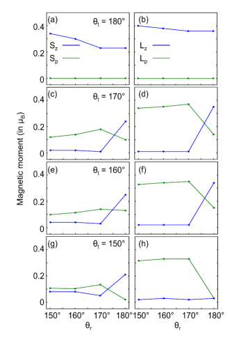
For / = 1 and = 4 eV, the planar and normal spin and orbital moments are plotted as a function of and in Fig. 8. In the absence of tilting, = 180∘, see Figs. 8(a,b), system always favours collinear spin ordering with vanishing and components. As far as is concerned, it increases with for = 180∘, hence, increasing the total magnetization of the system. Finite tilting (see Figs. 8(c,e,g)) leads to non-coplanar spin arrangement where decreases sharply with increasing component upto = 170∘. With further increase in , component decreases whereas component increases and finally both components become comparable for higher values of . More or less the component also follow the same trend as the with increase in but with magnitude larger as compare to the (see Figs. 8(d,f,h)). However, for = 150∘, the component vanishes completely suggesting quenching of component for higher . The isospin reorientation with tilting and rotation that we get from this first-principles study is attributed to the orbital mixing hoppings arising in the distorted frame. Many body models are being designed to relate such spin anisotropy to the Kitaev-type interactions developed due to octahedral tilting Mohapatra et al. (2019).
VII Summary and Outlook
To summarize, we developed a multi-band model Hamiltonian and performed density functional calculations to study the electronic and magnetic structure of SrIrO3 and examined the role of onsite Coulomb repulsion and spin-orbit coupling in the cubic and distorted structural framework. Furthermore, we used SrIrO3 as a prototype to examine the electronic structure of low-spin perovskites in general by building phase diagram and also smoothly varied the rotation and tilting of the IrO6 octahedra to bring a third dimension into it. Our study reveals that eight quantum phases, namely, nonmagnetic metal, nonmagnetic Dirac semimetal, ferromagnetic metal, ferromagnetic insulator, G-type antiferromagnetic metal, G-type antiferromagnetic insulator, canted antiferromagnetic semimetal, and canted antiferromagnetic insulator as shown in Figs. 5 and 7 of the main text. The mechanism driving such phases are explained in details. Further, we find that each of them form a soft-boundary to allow a continuous phase transition from one phase to the other by varying the interaction strengths. The phase diagram is validated by mapping the ground state of the reported low-spin perovskites CaIrO3, BaIrO3, SrRhO3, LaRuO3 and YRuO3 in the phase diagrams.
By scanning the periodic table, we see that low-spin transition metal oxide perovskites can be designed by exploring the following group combinations: I-X, II-IX, III-VIII (KPdO3, RbPdO3, MgRhO3, ScRuO3, ScOsO3 and YOsO3, etc.). Theoretically, thermodynamical stability of such systems can be examined and experimental synthesis can be attempted with the advent of state of the art synthesis techniques such as atom by atom deposition methods and high pressure methods. Furthermore, the two formula unit double perovskite transition metal oxides with state can be thought of as sister members where similar competing interactions govern the system. In this way, the phases proposed in the phase diagram can be achieved. The interaction strengths can be varied under external stimuli such as pressure and strain, as well as through changing the chemical composition, design of heterostructures, etc. to induce quantum phase transition in these systems. As a whole, we believe that the present study will trigger experimental and theoretical studies to envisage novel quantum phases and applications.
VIII Acknowledgement
The authors would like to thank HPCE, IIT Madras for providing the computational facility. This work is funded by the Department of Science and Technology, India, through grant No. CRG/2020/004330.
Appendix A TRANSFORMATION OF HOPPING MATRICES UNDER ROTATION AND TILTING OF OCTAHEDRA
In this appendix we briefly explain the transformation of TB matrices for hopping between different sublattices under rotation and tilting of octahedra. Distortion can be described in the form of octahedral rotation and tilting which varies from one Ir-site to the another as shown in Fig. 1(a). Here, or signs on each Ir-site indicates the clockwise or counterclockwise rotation and tilting of octahedra. The transformation of hopping matrices is determined by a site dependent rotation matrix (Eq. A4) Mohapatra et al. (2018); Tinkham (1964). Denoting unrotated and rotated basis in the order (xy,yz,xz,x2 - y2,3z2 - r2) for A sublattice as and , for B sublattice as and , so that = R and = R′ , where R and R′ are corresponding rotation matrices for A and B sublattices, the hopping integral in the rotated basis is then given by,
| (15) |
Hence, the Hamiltonian in the rotated basis is given by,
| (16) |
The total rotation matrix for each site for Ir site can be described as the multiplication of two individual rotation and tilt matrices. The product is given by,
| (17) |
where R() denotes the pure rotation about the z axis whereas R() denotes the rotation about the crystal axis . For pure rotation about z axis, the Euler angles (,,) = (,0,0) whereas for tilting (,,) = (-45∘,,45∘), respectively. Using these Euler angles, R() and R() can be obtained using R given by
| (18) |
where = 1 and = 2 1.
In the rotated basis, the TB hopping matrices between A to B sublattice can be obtained by using the following equation,
| (19) |
where is the Hamiltonian is the unrotated basis. In compact form is expressed as,
| (20) |
with H =H and H = H = 0. The submatrix H in the expanded form is given by,
| (21) |
where,
| (22) |
Similarly, Hopping between A to A sublattice is given by,
| (23) |
where,
| (24) |
and the corresponding dispersions and hopping strength are given as,
| (25) |
Similarly, the transformation and corresponding sublattice hopping matrices for interlayer coupling are given by,
| (26) | ||||
| (27) |
| (28) |
| (29) |
and the corresponding dispersion relations and hopping strength are given as,
| (30) |
Appendix B GEOMETRICAL DESIGN FOR INDUCING ROTATION AND TILTING
The geometrical design for inducing rotation in the plane is shown in Fig. 9. This geometrical design differs from the equilibrium orthorhombic structure (see Fig. 10). For the former, the Ir-O bond lengths are uniform while the Ir-O-Ir bond-angles vary to facilitate the rotation and tilting. However, for the latter both bond-lengths and bond angles are anisotropic to minimize the energy. Therefore, this geometrical design can explicitly examine the effect of rotation and tilting on spin ordering. To do a quantitative measure of it, we have specifically considered the case of plane tilting only. For analyzing the effect of structural distortions, a supercell is designed. Further distortion is induced in the supercell geometry by displacing the oxygen atoms in the (for rotation) as well in the (for tilting) plane keeping the Ir-O bond length fixed. The geometrical design for inducing rotation is shown in Fig. 9. For facilitating , oxygen atoms are displaced from their mean position O(x,y) to O′(x′, y′). In this process the lattice parameter changes from to a′ to maintain the constant bond length. By using similar geometry the tilting is designed in the plane. The lattice parameter for distorted structure and the coordinates of displaced oxygen atoms are related to each other by the following equations,
| (31) | ||||
| (32) | ||||
| (33) |
Appendix C Comparison between bulk CaIrO3 and SrIrO3
We have carried out calculations using the experimentally synthesized structure of CaIrO3 Tsuchiya2007 to examine the possible phases that this compound exhibits in the - space. From the structural point of view CaIrO3 and SrIrO3 differs largely through tilting and rotation angles ( and ). For the former these are 153∘ and 156∘ while for the latter these are 141∘ and 143∘.
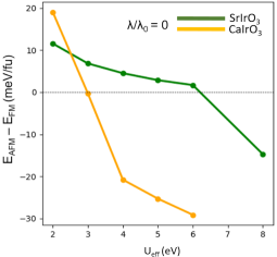
For comparison, instead of replicating the full phase diagram of SIO (see Fig. 5) we have picked multiple points from each domain and calculated the electronic structure on these points to validate the acceptability of the phase diagram. The results are shown in Fig. 11. We indeed found the stabilization of five phases: FM, G-AFI, CAFS, CAFI and DSM. The electronic structure of few selective points are marked on the bulk phase diagram of SIO and are shown in Fig. 11. The ground state DSM phase of CIO is very well captured (see band structure in the bottom pannel). Also, as seen in the case of SIO, the CAFI phase stabilizes for intermediate and higher values of / and . Here, the boundaries of the phase diagrams should not be treated as hard boundaries and they might vary depending on the compound and due to different rotation and tilting angles. As can be seen from Fig. 12, in the case of CIO, we find that the system stabilizes in the G-AFI state beyond = 3 eV whereas for SIO the G-AFI state stabilizes beyond 6 eV. These G-AFI states are formed with low-spin states.
Appendix D Robustness of the cubic metallic phase
In Fig. 13, we have plotted the spin and orbital resolved DOS as a function of and for / = 0. As can be clearly seen from the DOS of cubic (undistorted) SIO, for = 0, the eg states are highly delocalized (bandwidth is 6 eV) and nearly unoccupied.
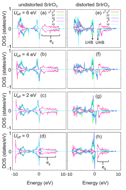
For such states the role of onsite Coulomb repulsion is negligible which indeed is reflected for higher values of . In fact, with stronger , the states are now completely unoccupied. As a result the system will always stabilize in a low-spin (te) metallic state. When we introduce the experimentally observed distortions, reduced hopping decreases the bandwidth (see column 2 of Fig. 13). However, the eg bandwidth is still large and there is a distortion induced bandgap which keeps the eg states unoccupied. In this case increasing creates lower and upper Hubbard bands (LHB and UHB) out of the t2g states and a new band gap emerges at the Fermi level (see Figs. 13 (f,e)).
References
- Hasan and Kane (2010) M. Z. Hasan and C. L. Kane, Rev. Mod. Phys. 82, 3045 (2010).
- Qi and Zhang (2011) X.-L. Qi and S.-C. Zhang, Rev. Mod. Phys. 83, 1057 (2011).
- Pesin and Balents (2010) D. Pesin and L. Balents, Nat. Phys. 6, 376 (2010).
- Bergholtz and Liu (2013) E. J. Bergholtz and Z. Liu, Int. J. Mod. Phys. B 27, 1330017 (2013).
- Baskaran et al. (2007) G. Baskaran, S. Mandal, and R. Shankar, Phys. Rev. Lett. 98, 247201 (2007).
- Takagi et al. (2019) H. Takagi, T. Takayama, G. Jackeli, G. Khaliullin, and S. E. Nagler, Nat. Rev. Phys. 1, 264 (2019).
- Okamoto et al. (2007) Y. Okamoto, M. Nohara, H. Aruga-Katori, and H. Takagi, Phys. Rev. Lett. 99, 137207 (2007).
- Yan and Felser (2017) B. Yan and C. Felser, Annu. Rev. of Condens. Matter Phys. 8, 337 (2017).
- Vafek and Vishwanath (2014) O. Vafek and A. Vishwanath, Annu. Rev. Condens. Matter Phys. 5, 83 (2014).
- Wan et al. (2012) X. Wan, A. Vishwanath, and S. Y. Savrasov, Phys. Rev. Lett. 108, 146601 (2012).
- Wan et al. (2011) X. Wan, A. M. Turner, A. Vishwanath, and S. Y. Savrasov, Phys. Rev. B 83, 205101 (2011).
- Witczak-Krempa et al. (2013) W. Witczak-Krempa, A. Go, and Y. B. Kim, Phys. Rev. B 87, 155101 (2013).
- Topp et al. (2018) G. E. Topp, N. Tancogne-Dejean, A. F. Kemper, A. Rubio, and M. A. Sentef, Nat. Commun. 9, 4452 (2018).
- Rau et al. (2014) J. G. Rau, E. K.-H. Lee, and H.-Y. Kee, Phys. Rev. Lett. 112, 077204 (2014).
- Chaloupka et al. (2013) J. c. v. Chaloupka, G. Jackeli, and G. Khaliullin, Phys. Rev. Lett. 110, 097204 (2013).
- Reuther et al. (2014) J. Reuther, R. Thomale, and S. Rachel, Phys. Rev. B 90, 100405 (2014).
- Takahashi et al. (2019) S. K. Takahashi, J. Wang, A. Arsenault, T. Imai, M. Abramchuk, F. Tafti, and P. M. Singer, Phys. Rev. X 9, 031047 (2019).
- Kenney et al. (2019) E. M. Kenney, C. U. Segre, W. Lafargue-Dit-Hauret, O. I. Lebedev, M. Abramchuk, A. Berlie, S. P. Cottrell, G. Simutis, F. Bahrami, N. E. Mordvinova, G. Fabbris, J. L. McChesney, D. Haskel, X. Rocquefelte, M. J. Graf, and F. Tafti, Phys. Rev. B 100, 094418 (2019).
- Nauman et al. (2017) M. Nauman, Y. Hong, T. Hussain, M. S. Seo, S. Y. Park, N. Lee, Y. J. Choi, W. Kang, and Y. Jo, Phys. Rev. B 96, 155102 (2017).
- Kim et al. (2008) B. J. Kim, H. Jin, S. J. Moon, J.-Y. Kim, B.-G. Park, C. S. Leem, J. Yu, T. W. Noh, C. Kim, S.-J. Oh, J.-H. Park, V. Durairaj, G. Cao, and E. Rotenberg, Phys. Rev. Lett. 101, 076402 (2008).
- Watanabe et al. (2013) H. Watanabe, T. Shirakawa, and S. Yunoki, Phys. Rev. Lett. 110, 027002 (2013).
- Yan et al. (2015) Y. J. Yan, M. Q. Ren, H. C. Xu, B. P. Xie, R. Tao, H. Y. Choi, N. Lee, Y. J. Choi, T. Zhang, and D. L. Feng, Phys. Rev. X 5, 041018 (2015).
- Fujiyama et al. (2012) S. Fujiyama, K. Ohashi, H. Ohsumi, K. Sugimoto, T. Takayama, T. Komesu, M. Takata, T. Arima, and H. Takagi, Phys. Rev. B 86, 174414 (2012).
- Chen et al. (2015) Y. Chen, Y.-M. Lu, and H.-Y. Kee, Nat. Commun. 6, 6593 (2015).
- Nie et al. (2015) Y. F. Nie, P. D. C. King, C. H. Kim, M. Uchida, H. I. Wei, B. D. Faeth, J. P. Ruf, J. P. C. Ruff, L. Xie, X. Pan, C. J. Fennie, D. G. Schlom, and K. M. Shen, Phys. Rev. Lett. 114, 016401 (2015).
- Fujioka et al. (2017) J. Fujioka, T. Okawa, A. Yamamoto, and Y. Tokura, Phys. Rev. B 95, 121102 (2017).
- Fujioka et al. (2019) J. Fujioka, R. Yamada, M. Kawamura, S. Sakai, M. Hirayama, R. Arita, T. Okawa, D. Hashizume, M. Hoshino, and Y. Tokura, Nat. Commun. 10, 362 (2019).
- Fujioka et al. (2021) J. Fujioka, R. Yamada, T. Okawa, and Y. Tokura, Phys. Rev. B 103, L041109 (2021).
- Carter et al. (2012) J.-M. Carter, V. V. Shankar, M. A. Zeb, and H.-Y. Kee, Phys. Rev. B 85, 115105 (2012).
- Cheng et al. (2013) J.-G. Cheng, T. Ishii, H. Kojitani, K. Matsubayashi, A. Matsuo, X. Li, Y. Shirako, J.-S. Zhou, J. B. Goodenough, C. Q. Jin, M. Akaogi, and Y. Uwatoko, Phys. Rev. B 88, 205114 (2013).
- Xia et al. (2017) H. Xia, J. Dai, Y. Xu, Y. Yin, X. Wang, Z. Liu, M. Liu, M. A. McGuire, X. Li, Z. Li, C. Jin, Y. Yang, J. Zhou, and Y. Long, Phys. Rev. Materials 1, 024406 (2017).
- Mathi Jaya et al. (1991) S. Mathi Jaya, R. Jagadish, R. S. Rao, and R. Asokamani, Phys. Rev. B 43, 13274 (1991).
- Singh (2003) D. J. Singh, Phys. Rev. B 67, 054507 (2003).
- Ji et al. (2020) K. Ji, A. Paul, E. Solana-Madruga, A. M. Arevalo-Lopez, U. V. Waghmare, and J. P. Attfield, Phys. Rev. Materials 4, 091402 (2020).
- Zeb and Kee (2012) M. A. Zeb and H.-Y. Kee, Phys. Rev. B 86, 085149 (2012).
- Torrance et al. (1992) J. B. Torrance, P. Lacorre, A. I. Nazzal, E. J. Ansaldo, and C. Niedermayer, Phys. Rev. B 45, 8209 (1992).
- García-Muñoz et al. (1992) J. L. García-Muñoz, J. Rodríguez-Carvajal, P. Lacorre, and J. B. Torrance, Phys. Rev. B 46, 4414 (1992).
- Miyasaka et al. (2003) S. Miyasaka, Y. Okimoto, M. Iwama, and Y. Tokura, Phys. Rev. B 68, 100406 (2003).
- Zhou et al. (2005) J.-S. Zhou, J.-Q. Yan, and J. B. Goodenough, Phys. Rev. B 71, 220103 (2005).
- Zhou et al. (2010) J.-S. Zhou, J. A. Alonso, V. Pomjakushin, J. B. Goodenough, Y. Ren, J.-Q. Yan, and J.-G. Cheng, Phys. Rev. B 81, 214115 (2010).
- Vogt et al. (2003) T. Vogt, J. A. Hriljac, N. C. Hyatt, and P. Woodward, Phys. Rev. B 67, 140401 (2003).
- Kim et al. (2017) B. Kim, P. Liu, and C. Franchini, Phys. Rev. B 95, 115111 (2017).
- Liu et al. (2015) P. Liu, S. Khmelevskyi, B. Kim, M. Marsman, D. Li, X.-Q. Chen, D. D. Sarma, G. Kresse, and C. Franchini, Phys. Rev. B 92, 054428 (2015).
- Zhao et al. (2008) J. G. Zhao, L. X. Yang, Y. Yu, F. Y. Li, R. C. Yu, Z. Fang, L. C. Chen, and C. Q. Jin, J. App. Phys. 103, 103706 (2008).
- Kresse and Joubert (1999) G. Kresse and D. Joubert, Phys. Rev. B 59, 1758 (1999).
- Blöchl (1994) P. E. Blöchl, Phys. Rev. B 50, 17953 (1994).
- Kresse and Furthmüller (1996) G. Kresse and J. Furthmüller, Phys. Rev. B 54, 11169 (1996).
- Dudarev et al. (1998) S. L. Dudarev, G. A. Botton, S. Y. Savrasov, C. J. Humphreys, and A. P. Sutton, Phys. Rev. B 57, 1505 (1998).
- Longo et al. (1971) J. Longo, J. Kafalas, and R. Arnott, J. Solid State Chem. 3, 174 (1971).
- Modic et al. (2014) K. A. Modic, T. E. Smidt, I. Kimchi, N. P. Breznay, A. Biffin, S. Choi, R. D. Johnson, R. Coldea, P. Watkins-Curry, G. T. McCandless, J. Y. Chan, F. Gandara, Z. Islam, A. Vishwanath, A. Shekhter, R. D. McDonald, and J. G. Analytis, Nat. Commun. 5, 4203 (2014).
- Boseggia et al. (2013) S. Boseggia, R. Springell, H. C. Walker, H. M. Rønnow, C. Rüegg, H. Okabe, M. Isobe, R. S. Perry, S. P. Collins, and D. F. McMorrow, Phys. Rev. Lett. 110, 117207 (2013).
- Chaloupka and Khaliullin (2016) J. Chaloupka and G. Khaliullin, Phys. Rev. B 94, 064435 (2016).
- Biffin et al. (2014) A. Biffin, R. D. Johnson, I. Kimchi, R. Morris, A. Bombardi, J. G. Analytis, A. Vishwanath, and R. Coldea, Phys. Rev. Lett. 113, 197201 (2014).
- Slater and Koster (1954) J. C. Slater and G. F. Koster, Phys. Rev. 94, 1498 (1954).
- Luo (2013) Q. Luo, Numerical Study of Hubbard Model for Iron-based Superconductors, PhD diss.,University of Tennessee (2013).
- Kanamori (1963) J. Kanamori, Progress of Theoretical Physics 30, 275 (1963).
- Mohapatra et al. (2019) S. Mohapatra, S. Aditya, R. Mukherjee, and A. Singh, Phys. Rev. B 100, 140409 (2019).
- Kobayashi et al. (1994) H. Kobayashi, M. Nagata, R. Kanno, and Y. Kawamoto, Materials Research Bulletin 29, 1271 (1994).
- Hogan et al. (2016) T. Hogan, L. Bjaalie, L. Zhao, C. Belvin, X. Wang, C. G. Van de Walle, D. Hsieh, and S. D. Wilson, Phys. Rev. B 93, 134110 (2016).
- Meyers et al. (2019) D. Meyers, Y. Cao, G. Fabbris, N. J. Robinson, L. Hao, C. Frederick, N. Traynor, J. Yang, J. Lin, M. H. Upton, D. Casa, J.-W. Kim, T. Gog, E. Karapetrova, Y. Choi, D. Haskel, P. J. Ryan, L. Horak, X. Liu, J. Liu, and M. P. M. Dean, Sci. Rep. 9, 4263 (2019).
- Mohapatra et al. (2018) S. Mohapatra, C. Bhandari, S. Satpathy, and A. Singh, Phys. Rev. B 97, 155154 (2018).
- Tinkham (1964) M. Tinkham, Group Theory and Quantum Mechanics, McGraw-Hill, New York (1964).
- (63) Tsuchiya, T. & Tsuchiya, J. Phys. Rev. B 76, 144119 (2007).
- (64) Meetei, O. N., Cole, W. S., Randeria, M. & Trivedi, N. Phys. Rev. B 91, 054412 (2015).