Stripe-yz magnetic order in the triangular-lattice antiferromagnet KCeS2
Abstract
Yb- and Ce-based delafossites were recently identified as effective spin-1/2 antiferromagnets on the triangular lattice. Several Yb-based systems, such as NaYbO2, NaYbS2, and NaYbSe2, exhibit no long-range order down to the lowest measured temperatures and therefore serve as putative candidates for the realization of a quantum spin liquid. However, their isostructural Ce-based counterpart KCeS2 exhibits magnetic order below mK, which was so far identified only in thermodynamic measurements. Here we reveal the magnetic structure of this long-range ordered phase using magnetic neutron diffraction. We show that it represents the so-called “stripe-” type of antiferromagnetic order with spins lying approximately in the triangular-lattice planes orthogonal to the nearest-neighbor Ce–Ce bonds. No structural lattice distortions are revealed below , indicating that the triangular lattice of Ce3+ ions remains geometrically perfect down to the lowest temperatures. We propose an effective Hamiltonian for KCeS2, based on a fit to the results of ab initio calculations, and demonstrate that its magnetic ground state matches the experimental spin structure.
1 Introduction
In low-dimensional quantum magnets, competing exchange interactions may lead to a strong frustration accompanied by enhanced quantum fluctuations. Ultimately this can prevent the systems from long-range order, and the ground state is supposed to be a quantum spin liquid (QSL) [1, 2, 3, 4]. The theoretically predicted QSL state remains experimentally elusive, and a major ongoing research effort is directed towards the identification of promising QSL candidate materials [5].
Two most promising search directions are pursued. The first is motivated by the seminal work of Kitaev [6] and is focused on materials with anisotropic Kitaev interactions on tricoordinated lattices [7, 8, 9, 10, 11, 12, 13, 14, 15, 16, 17, 18, 19, 20]. There is no requirement of geometrical frustration in this case, because the frustration originates from highly anisotropic nearest-neighbor interactions that can result from strong spin-orbit coupling. The most promising candidate compounds in this class are honeycomb-lattice iridates (-Li2IrO3, Na2IrO3, H3LiIr2O6) [7, 8, 9, 10, 11] or ruthenates (-RuCl3) [14, 15, 16, 17, 18] and their three-dimensional polymorphs that form hyper-honeycomb (-Li2IrO3) [12] or stripy-honeycomb (-Li2IrO3) [13] structures. The difficulty with these model systems is that in real materials, Kitaev interactions coexist with Heisenberg exchange and other possible types of interactions, leading to very intricate magnetic Hamiltonians [21, 20, 22]. Existing materials usually end up in different regions of the multidimensional parameter space away from the relatively small theoretically predicted stability regions of the QSL state.
The second search direction rests on the original proposal by Anderson [23] that a QSL ground state can be realized in two-dimensional (2D) spin-1/2 triangular-lattice antiferromagnets (TLAF) as a result of geometrical frustration [24, 25]. The same is true also for other highly frustrated antiferromagnetic (AFM) 2D lattices, such as the kagome lattice [26], which is realized in many copper-containing compounds where quantum spins reside on the magnetic Cu2+ ions, most famously in herbertsmithite [27, 28, 29, 30]. The difficulty with these systems, however, is that the lattice may experience small structural distortions which are often sufficient to relieve the frustration [30, 31]. Moreover, to the best of our knowledge, no realizations of an undistorted AFM triangular lattice of Cu2+ spins have been identified to date among inorganic compounds. Therefore, the most suitable materials for the experimental verification of theoretical spin-1/2 models on the triangular lattice are layered rare-earth compounds with Ce3+ or Yb3+ ions, characterized by the 4f1 and 4f13 electronic configurations, respectively. Whenever the ground-state doublet is sufficiently separated from higher-energy states due to the crystal electric field (CEF) splitting, these ions realize an effective state at low temperatures. The most studied QSL candidate from this class is YbMgGaO4 [32, 33, 34, 35], although most recent studies tend to attribute the absence of long-range order in this material to Mg- Ga3+ site intermixing [36, 37].
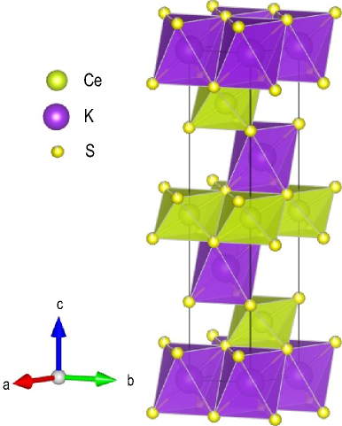
A short while ago, a whole new family of compounds with the undistorted triangular lattice of rare-earth ions with little or no structural disorder has been identified [39, 40, 41, 42]. These are ternary compounds with the general chemical formula , where is an alkali metal (e.g. Na, K, Rb, Cs), is a rare-earth ion (in our case, Ce or Yb), and is a chalcogen atom (O, S, or Se). They crystallize in the layered delafossite structure depicted in Fig. 1 that derives from the rock-salt structure upon cation ordering, realizing ABAB-type stacking of magnetic triangular-lattice layers [43, 44]. Low-temperature thermodynamic measurements reveal no signatures of magnetic ordering down to subkelvin temperatures in NaYbO2 [39, 45, 46, 47, 48], NaYbS2 [39, 40, 49], and NaYbSe2 [39, 50, 51, 52], indicating that these Yb-delafossite compounds may possess QSL ground states. Long-range magnetic order in these systems can be achieved in a moderate magnetic field [47, 50, 53]. On the other hand, their isostructural Ce-based counterpart KCeS2 develops magnetic order below 400 mK already in zero field, according to the specific-heat data [54].
Because Ce3+ and Yb3+ ions have one electron or hole in the shell, respectively, and the CEF schemes of all the mentioned compounds have ground-state doublets that are well separated from the excited CEF states [40, 46, 48, 54, 51, 55], one would generally expect the spin-1/2 approximation to be equally applicable to these systems. However, they may still differ in terms of the magnetocrystalline anisotropy and have different eigenfunctions of the CEF ground state with respect to their decomposition in the basis, which would place them in different regions of the parameter space of a generic effective Hamiltonian proposed for triangular-lattice antiferromagnets [56, 57]. To understand these differences, we have investigated the magnetic structure of the low-temperature ordered phase in KCeS2 and its low-temperature lattice structure using powder neutron diffraction.
2 Sample preparation
The powder sample of KCeS2 was prepared through the following synthesis route. Potassium carbonate and cerium dioxide were mixed in a 20:1 molar ratio and thoroughly ground in a porcelain mortar. A glassy carbon crucible was filled with this mixture and placed in a tube furnace. Before heating up to the target temperature, the whole apparatus including a reservoir for carbon disulfide was flushed with argon for 30 min. The mixture was heated up to 1050 ∘C within 3 hours under an unloaded stream of argon (5 L/h). While dwelling one hour, a stream of argon of 0.5 L/h was used to carry CS2 into the hot zone to enable the sulfidization. Finally, the apparatus was allowed to cool down to 600 ∘C within 6 hours and without further control down to ambient temperature under a slight argon stream. The ingot that formed in the glassy carbon crucible was then dissolved in water to set the insoluble KCeS2 free. Filtering via paper and funnel and washing with water and ethanol produced the sample, mainly composed of intergrown crystals of the target compound and some Ce2O2S as a minority phase. The formation of oxidic by-products during the formation of rare-earth metal chalcogenides (and other compounds of rare-earth metals) is well known and can be attributed to the high oxygen susceptibility of the rare-earth metal ions. It can only be prevented in a completely oxygen-free setup. We also observed that mechanical manipulations (such as pressing, grinding, etc.) can foster decomposition of KCeS2 with the formation of the Ce2O2S phase, therefore we avoided grinding the sample and used the as-synthesized powder in neutron-diffraction measurements.
3 Powder neutron diffraction
To reveal the spin structure in the low-temperature AFM state of KCeS2, we measured neutron powder diffraction at the D1B high-intensity two-axis powder diffractometer at ILL, France. Neutrons with a calibrated wavelength Å were selected with a highly oriented pyrolytic graphite (HOPG) (002) monochromator. The contribution of the instrument to the peaks broadening was determined from the refinement of Na2Ca3Al2F14 standard sample, while wavelengths were refined using a Si standard. Parasitic diffraction peaks arising from the sample environment were eliminated by a radial oscillating collimator. Our delafossite sample represented rough powder consisting of small crystallites with lateral sizes up to 0.5 mm. This sample was placed in a Cu can to ensure good thermal contact at subkelvin temperatures and was cooled down using a dilution refrigerator. The measurements were carried out while the sample was rotated about the vertical axis within 180∘ with a step of 1∘ (for the 72 and 600 mK datasets) or 3∘ (other temperatures), with subsequent averaging of the datasets to compensate for the preferred orientations of individual crystallites. The data were collected at several temperatures between 72 and 600 mK in zero magnetic field, allowing for sufficient time for temperature stabilization before every data collection. The measurements at base temperature and at 600 mK were measured with higher statistics, corresponding to approximately 13 h acquisition time per temperature for the 72 and 600 mK datasets.
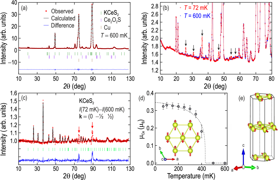
The 600 mK dataset, collected above , is plotted in Fig. 2 (a). Apart from the structural reflections from the main KCeS2 phase, it contains reflections from the paramagnetic impurity phase Ce2O2S [58, 59], which constitutes about 15% of our sample judging from the results of structural refinement but exhibits no magnetic Bragg reflections. There are also two intense peaks from metallic copper that originate from the sample container, which we included as the third phase. Our Rietveld refinement of the neutron data was done in the assumption of the rhombohedral space group, previously reported for KCeS2 from x-ray structure refinement [60, 54]. The agreement between the lattice structures obtained at room temperature and at 600 mK (apart from the changes in lattice constants due to thermal expansion) demonstrates the absence of any symmetry-lowering transitions down to . The low-temperature lattice parameters resulting from the refinement of our neutron data are summarized in Table 1.
Parameters KCeS2 Ce2O2S Fraction 84.3% 15.7% Space group (#166) (#162) Temperature 72 mK 600 mK 72 mK 600 mK (Å) 4.2242(1) 4.2243(1) 4.0011(3) 4.0015(2) (Å) 21.836(1) 21.836(1) 6.888(1) 6.888(1) (Å3) 337.44(2) 337.46(2) 95.50(1) 95.52(1) 0.43(2) 0.43(2) — — 0.28(1) 0.28(1) — 0.62(1) 0.62(1) 2.59 2.45 2.59 2.45 5.53 5.18 5.53 5.18 5.66 5.53 5.66 5.53
The magnetic peaks, shown in the 72 mK dataset in Fig. 2 (b) with black arrows, set in below 400 mK — the transition temperature revealed earlier in specific-heat measurements [54]. The difference of the low- and high-temperature datasets, plotted in Fig. 2 (c), contains only magnetic Bragg peaks, whereas the structural scattering from KCeS2 and the oxysulphide impurity phase is subtracted to zero, which presents strong evidence for the absence of any structural phase transition associated with the magnetic ordering. The commensurate AFM propagation vector was determined by the K_Search algorithm in the FullProf Suite based on difference of the two datasets. Representation analysis carried out with SARAh [61] for the space group with the aforementioned propagation vector suggests two possible common irreducible representations: and , which we have checked against the temperature-subtracted dataset. Our final result of the magnetic structure refinement, which was done using FullProf Suite [62], is shown in Fig. 2 (c) with a black line. The magnetic signal can be perfectly described only using the irreducible representation. Note that the two peaks marked with red arrows are of nonmagnetic origin, as they result from the imperfect subtraction of strong structural reflections from Cu. The magnetic structure of KCeS2 is collinear, with spins lying approximately in the plane and pointing orthogonally to the nearest-neighbor Ce-Ce bonds, as shown in the inset to Fig. 2 (d). The refinement suggests a statistically insignificant out-of-plane canting of Ce3+ spins by , yet fixing this angle to zero has no significant effect on the quality of the fit, so also the in-plane spin arrangement would be consistent with our data. This type of AFM structure on the triangular lattice is known as “stripe-” order among theorists [56, 57, 63, 64]. The stacking of the AFM layers along the out-of-plane direction is illustrated in Fig. 2 (e). Note that all magnetic Bragg peaks in Fig. 2 (c) are well described with our model for KCeS2, suggesting that the impurity phase Ce2O2S develops no magnetic order down to 20 mK and could be therefore itself considered a promising spin-liquid candidate.
According to our combined refinement of the magnetic and structural data, the ordered magnetic moment on Ce3+ at base temperature is approximately . It decreases monotonically with increasing temperature, as shown in Fig. 2 (d), following order-parameter behavior. Fitting this dependence with the empirical function , shown with a dotted line, gives a transition temperature mK, which is slightly higher than the value previously observed in thermodynamic measurements [54]. The ordered moment in our data saturates below 300 mK, which may be a consequence of poor temperature stabilization in the powder sample close to the base temperature of the dilution refrigerator. Therefore, it cannot be excluded that we somewhat underestimate the value of the ordered moment at the base temperature.
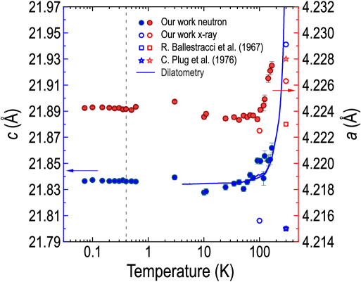
From the structural refinement of neutron diffraction data, we also obtained the temperature dependence of lattice constants, as it is shown in Fig. 3 with solid circles. For comparison, we also show our own and previously published cell parameters [65, 60] obtained using x-ray diffraction. Both lattice parameters and show conventional (positive) thermal expansion above 100 K, whereas below this temperature the thermal expansion is rather small and not measurable within the experimental error. We compare this result with the -axis thermal expansion measured by capacitive dilatometry (solid line), carried out using our in-house dilatometer with a sensitivity to relative length changes of about [66]. The specimen consisted of several flakelike single crystals of KCeS2 stacked along the axis to achieve a minimum required sample thickness. Therefore, only thermal expansion along the axis but not in the plane could be measured. In good agreement with the neutron diffraction data, the capacitive dilatometry confirms a really small thermal expansion below 120 K, where the relative length change is only . The linear expansion coefficient stays less than K-1 in this temperature range and only increases noticeably at higher temperatures. Additionally, nearly no magnetostriction could be detected during field sweeps (not shown), where the relative length change is only about up to 8 T at K. The crossover in the behavior of the thermal expansion, observed consistently in diffraction and dilatometry, occurs more than two orders of magnitude higher in temperature than the magnetic ordering transition, which suggests that magnetostrictive effects become effective far above the Néel temperature due to the strong frustration in the system. Moreover, we observe no magnetostriction anomaly at the magnetic ordering temperature (dashed vertical line) in our neutron data. This is another indication that the AFM state is accompanied with no structural distortions, and the delafossite lattice structure with geometrically perfect triangular-lattice layers remains stable even after the stripe- AFM order sets in.
4 Theory
4.1 DFT/PBE/PAW level
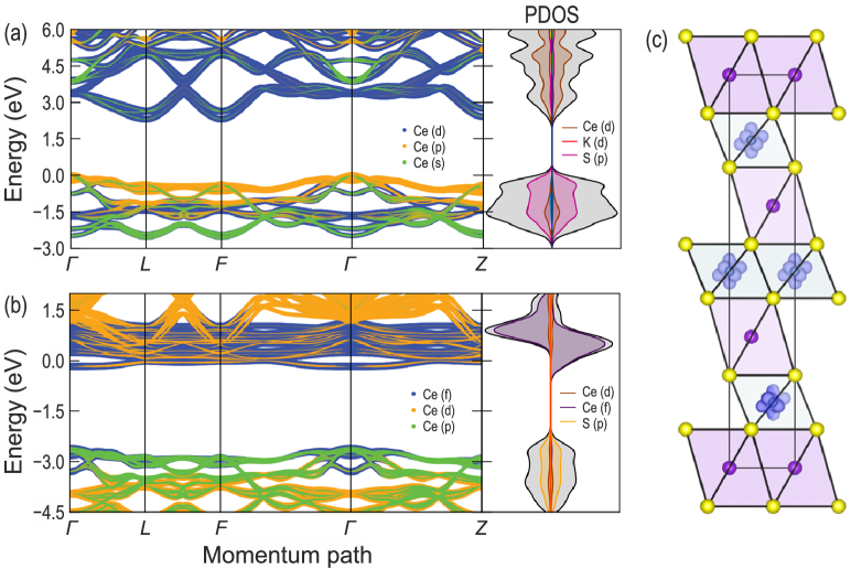
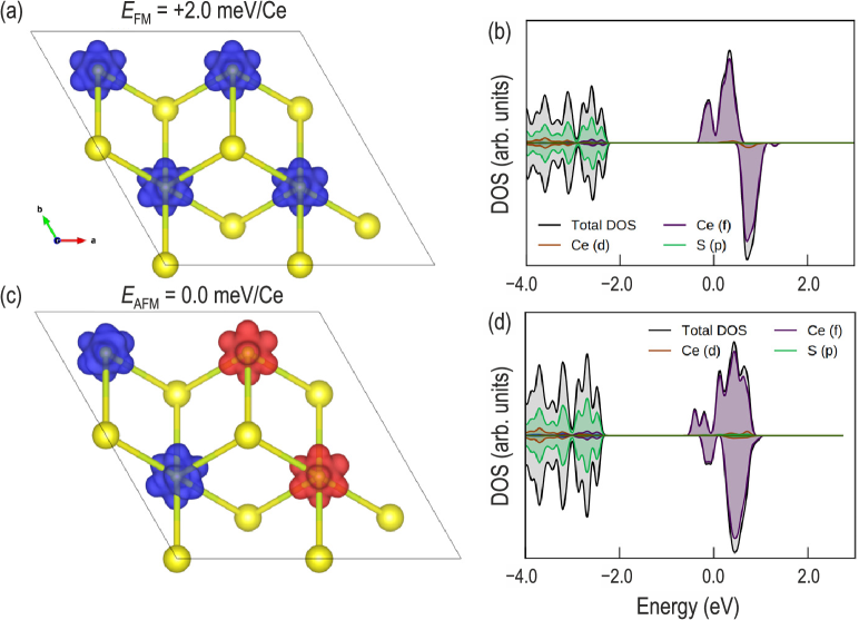
We start the theoretical investigation at the density-functional theory (DFT/PBE/PAW) level using VASP suit[67, 68, 69]. Admittedly any single-determinant approximation would be a weak one for the 4f system without special arrangements for -shell. To deal with the complication due to the 4f shell, at first the shell in core potential for Ce is considered [69]. The -centered grid of was used for system optimization and charge density convergence with plane-wave basis cutoff of 400 eV. The original rhombohedral structure has been optimized down to 10-4 eV/Å level with no restrictions on symmetry. The optimized structure preserves the original space group but acquires a slightly expanded unit cell compared to the experimental data, Å vs. Å and Å vs. Å. While the lattice parameter remains within the experimental uncertainty from the measured value, the lattice constant experiences a significant (0.78%) expansion along the axis, which accounts for 0.026 Å expansion of the CeS6 trigonal antiprism along the axis. Nevertheless, the electronic structure is only slightly affected by these differences. Figure 4 shows the band structure profiles along the high symmetry lines of KCeS2 with 4f shell in the core and explicit 4f-shell treatment. Expectedly, with 4f electrons in the core, KCeS2 represents an indirect-gap semiconductor with large 2.7 and 2.3 eV direct and indirect gaps, respectively, as seen in Fig. 4 (a). Explicit 4f-shell treatment produces a localized state around the Fermi level with a small dispersion driven by d-f hybridization. At the point, the d-f hybridization is minimal with a formal gap of 0.05 eV (within the f shell) and approximately 1.0 eV difference between the populated f shell and the bottom of p-d bands at the point. Without alteration of original per-site magnetization, the spin-polarized solution is converged to a ferromagnetic (FM) state as it is indicated by spin density (or magnetization density) in Fig. 4 (c).
Next, we estimate the magnetization energy, using the same DFT level as before, by optimizing a single-determinant wave function for different total magnetization densities: for the FM state and for the AFM state. Here, a proper consideration would require a supercell at least accommodating one propagation vector. However, the system of this size will suffer a lot more from well-known DFT shortcomings than a smaller system, and the question of applicability alone would need a separate study. Therefore, here we restrict the consideration to a fragment of a single isolated CeS2 layer in a supercell, as shown in Fig. 5. We find that thermodynamically the AFM state is more stable than the FM state by 2.0 meV/Ce, as indicated in Figs. 5 (a,c). Similar to the complete system, the f shells form condensed and localized bands around the Fermi level for both spin constraints [see Fig. 5 (b,d)]. Although the f shell in the partial density of states (PDOS) has significant rearrangements, the spin density is well localized on the Ce sites and looks very similar before and after the spin flip. Further investigation of the moment orientation will require noncollinear consideration with a spin-orbit coupling Hamiltonian in place. This consideration would, even more, stretch the reliability of the DFT model in its application to f-shell systems modeling. Moreover, 4f systems have a strictly multiconfigurational character of the ground state -multiplet (with ). This cannot be easily accounted for with any DFT model. Multiconfigurational methods such as the complete active space self-consistent field (CASSCF) are generally inapplicable to a periodic system and limited to cluster approximations.
4.2 CASSCF(1,7)/RASSI/SO modeling
Luckily, we find our shell well isolated in the system. From band structures in Fig. 4, we find that around the point, the 4f states remain factorized from unoccupied states (lack of d- or p-projections and small contributions along the k path). Also, the noticeable contribution of the shell to the valance bands is likely an artifact of d+p and -shell projection procedure.
Thus, to understand the local properties, we can restrict our consideration to the local polyhedron (minimal cluster of CeS6) only. Moreover, as it was shown previously, the local properties of Ce centers in ESR spectra can be rationalized from very simple approximations [54]. Here, we elaborate more on this simple theoretical picture using the full strength of multiplet modeling based on Stevens parameters predicted through either point-charge models (using McPhase[70] program and in-house Python scripts) or the CASSCF(1,7)/ANO-RCC-VDZP/RASSI/SO modeling (with OpenMolcas code[71, 72]). We find that apart from some small scaling, both models provide virtually identical results and, for all intents and purposes, can be used interchangeably. We also apply the same level of theory to the impurity phase Ce2O2S for comparison and better understanding of the experimental results.
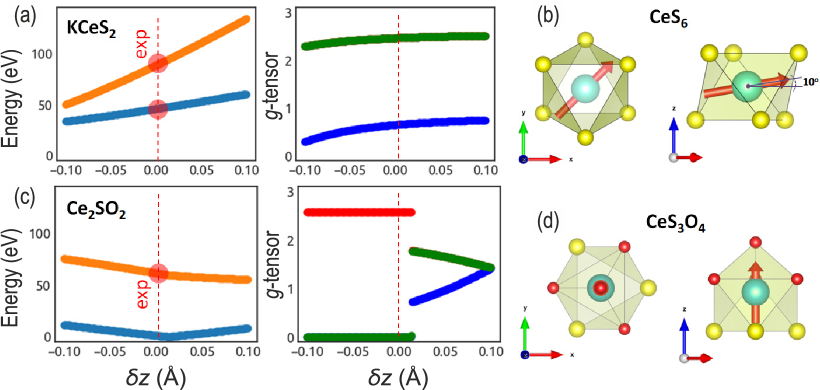
Figures 6 (b, d) show two different projections of the CeS6 and CeS3O4, respectively, based on the experimentally refined lattice parameters. In the case of CeS3O4 with an easy-axis anisotropy, the direction of the moment coincides with the direction of the main magnetic axis along . For the “easy-plane” situation in the CeS6 cluster, the anisotropy ellipsoid and the radii are given by the tensor provided in Table 2. Still, it is possible to evaluate total angular momentum components along the main magnetic axis, . With no external perturbation, this moment has Larmor precession in a plane that is tilted with respect to the plane, which is consistent with the moment canting suggested by the refinement of the magnetic structure from neutron diffraction in section 3.
To gain more confidence in the employed theoretical framework, we first studied the impact of the compression/elongation along the -axis of local Ce polyhedra (CeS6 for KCeS2 and CeS3O4 for Ce2O2S). Figure 6 shows the multiplet transformation (state energies and tensor of the ground state) as a function of the elongation defined relative to the experimentally refined crystal structure. Interestingly, drastic changes in the state -energy diagram are observed within a small deviation of only Å from the experimental value. For example, for KCeS2 (CeS6 cluster) the energies for the second and third states can change almost twofold and threefold, respectively, in this range. At the same time for Ce2O2S the situation is much more complex. Apart from the pronounced energy change, the system undergoes two local phase transitions from the easy-axis to easy-plane and back to easy-axis as changes from 0.0 to 0.1. The detailed analysis of this phenomenon is outside the scope of this work, so we leave it for follow-up studies. In the following, we compare relative state energies around the experimental geometries and their compositions (Table 2).
| System | Energy (meV) | Wave function | INS, barn | |||
|---|---|---|---|---|---|---|
| KCeS2 | 0.00 | 2.47 | 2.47 | 0.65 | 1.91 | |
| (CeS6) | 46.00 | 0.00 | 0.00 | 2.57 | 1.76 | |
| 88.98 | 0.1 | 0.1 | 4.08 | 0.23 | ||
| Ce2O2S | 0.00 | 0.00 | 0.00 | 2.57 | 0.81 | |
| (CeS3O4) | 3.75 | 1.818 | 1.818 | 0.650 | 1.29 | |
| 61.55 | 0.753 | 0.753 | 2.780 | 1.06 |
In our previously published inelastic neutron scattering (INS) data [54], we observed one additional CEF excitation beyond those allowed for the Ce3+ ion in KCeS2. Such additional CEF lines may arise from an impurity phase [40], from modified local environment due to lattice defects, such as stacking faults [73, 48], or from vibron quasibound states that result from strong magnetoelastic coupling [74, 75]. It is therefore important to verify whether the Ce2O2S impurity phase identified in our present work can account for this additional excitation. In the framework of the point-charge model, we have optimized the S-ion charge at , so that the first excited state of the multiplet matches the most intense experimental CEF transition at 46 meV, while using the experimental geometries for polyhedral CeS6 and CeS3O4. In the case of CeS3O4, the O-ion point charge is assumed equal to that of the S ion, scaled by the ratio of Hirshfeld population () predicted by the DFT model: . The calculated intensities of the INS cross section for CEF transitions in both compounds are calculated using the state energies and the wave functions and are given in Table 2. Taking the linear combination of the resulting spectra in the proportion KCeS2 : Ce2O2S = 85 : 15 (corresponding to the results of structural refinement given in Table 1), we can reproduce both the energies and intensities of the experimental INS spectrum with remarkable accuracy (see Fig. 7). This modeling suggests that the highest-energy peak at 74 meV originates from the KCeS2 majority phase, despite its low intensity, whereas the additional peak at 62 meV can be assigned to the oxysulphide phase. As long as the charge of the ions changes consistently for both phases, the Ce2O2S excitation is always located between the two peaks originating from KCeS2. This leaves no ambiguity in the assignment of the experimental CEF lines.
![[Uncaptioned image]](/html/2107.04402/assets/x7.png) Figure 7: (a,b) 2D regular raster map of inelastic neutron scattering (INS) signals in energy-compression () coordinates for KCeS2 and Ce2O2S at K. (c) INS spectra of individual KCeS2 () and Ce2O2S () phases with experimental local polyhedron geometries () and an average spectrum weighted with experimental proportion between and .
Figure 7: (a,b) 2D regular raster map of inelastic neutron scattering (INS) signals in energy-compression () coordinates for KCeS2 and Ce2O2S at K. (c) INS spectra of individual KCeS2 () and Ce2O2S () phases with experimental local polyhedron geometries () and an average spectrum weighted with experimental proportion between and .
4.3 The effective Hamiltonian parameterization
To understand the origin of magnetic ordering in KCeS2 and be able to compare it with rare-earth delafossites with a quantum-disordered ground state, we need to estimate effective interactions between local moments. The chosen DFT level predicts 2.0 meV/Ce, but this method is notoriously ill-equipped for such tasks. Thus, ab initio verifications are needed.
For ab initio estimations, however, one has to consider at least two interacting Ce3+ ions at the same quantum-mechanical level. Fortunately, a pair of Ce3+ atoms with 4f1 configuration each and an AFM ground state () can be described by CASSCF(2,14)/ANO-RCC-VDZP/RASSI/SO problem with just 105 roots (Slater determinants) [71]. This model produces the six low-lying spin orbitals within 60 meV. They comprise a single ground-state singlet, followed by a quasi-doublet at 5.1 meV, an excited singlet at 10.3 meV, and an excited quasi-doublet with an energy of 53.3 meV. For the single Ce3+-ion, the ab-initio ground-state multiplet structure can be reproduced by the minimal basis using the derived ab-initio Stevens parameters, , with 99.98% efficiency[72]. Assuming no significant electronic charge rearrangements (Ce3+ sites are well-localized) and the Lines model as a valid approximation [76], we can project the two-site ab initio solution on the following effective Hamiltonian in the basis
| (1) |
in the attempt to retrieve couplings.
| Moment model | |||||||||
|---|---|---|---|---|---|---|---|---|---|
| 5/2 | –0.70 | –0.60 | –4.90 | 0.0 | 0.0 | 0.0 | 0.0 | –0.8 | –0.8 |
| –0.12 | –0.10 | –0.81 | 0.0 | 0.0 | 0.0 | 0.0 | –0.13 | –0.13 |
![[Uncaptioned image]](/html/2107.04402/assets/x8.png) Figure 8: (a) Geometry of the two-site model for ab initio CASSCF(2,14)/RASSI/SO level calculations. (b) Magnetic order (orientation of the total moments) and on-site 4f charge-density isosurfaces in clusters with 2, 3, 4, and 13 sites. (c) Predicted magnetic unit cell in the CeS2 layer and the couplings parameters estimated based in the ab initio modeling of the two-sites system (see text for details).
Figure 8: (a) Geometry of the two-site model for ab initio CASSCF(2,14)/RASSI/SO level calculations. (b) Magnetic order (orientation of the total moments) and on-site 4f charge-density isosurfaces in clusters with 2, 3, 4, and 13 sites. (c) Predicted magnetic unit cell in the CeS2 layer and the couplings parameters estimated based in the ab initio modeling of the two-sites system (see text for details).
Using the Hamiltonian in Eq. (1), we fit the free parameters to ab initio states energies predicted at CASSCF(2,14)/RASSI/SO. We find using the PHI program [77] that the three lowest-energy states can be reproduced exactly with the optimized parameter values given in Table 3. Above 15.0 meV, the deviation in energy exceeds tens of meV, presumably due to contributions of the higher-order (multipolar) interactions for which the anisotropic Lines model, with dipolar interactions only, does not account. Moreover, the extracted Hamiltonian is based on the minimal two-site model which lacks the exact crystal symmetry and may overestimate local anisotropy contributions. Nonetheless, this model can describe the four low-lying states including the ground state. Thus, we conclude that this center symmetry model [Fig. 8 (a)] is able to predict noticeable anisotropy in interactions between local moments and sufficient to control total magnetic order in cluster models. To prove that, these interactions were further implemented in the localized-moments ordering models using the self-consistent mean-field method (see McPhase[70] for more details) for clusters of 2, 3, 4, and 13 sites and for fully periodic systems with proper -space sampling (Figure 8). Having allowed for the -sampling and a maximum unit cell up to 4 atoms in any direction, within the proposed interaction Hamiltonian, we obtain from this model the magnetic unit cell shown in Fig. 8 (f). This is consistent with the experimentally observed stripe- order and the ordered moment of 0.33 /Ce, which also agrees with the experimental value.
5 Discussion and conclusions
In this paper, we have presented the results of magnetic structure refinement for the low-temperature AFM state, which was recently revealed in the effective spin-1/2 triangular-lattice antiferromagnet KCeS2. It represents collinear stripe- AFM order with spins lying orthogonal to the nearest-neighbor Ce–Ce bonds in the plane, possibly with a small (10∘) out-of-plane canting of the magnetic moments that is also expected from theory. A similar stripe order was recently proposed for the closely related compound CeCd3As3 [64]. In addition, we have shown that there are no lattice distortions or symmetry-lowering structural transitions associated with the magnetic ordering to within 10-4. The thermal expansion remains very small ( K-1) below 120 K, which we confirmed for the lattice constant using capacitive dilatometry. Our experimental results also indicate that cerium oxysulphide, Ce2O2S, which was present in our sample as a minority phase, does not order magnetically down to 20 mK and may therefore represent a promising spin-liquid candidate deserving a separate study.
Following the experimental determination of the magnetic structure, we could explain it using first-principles calculations that predict exchange-coupling anisotropy in the pair interaction between two neighboring Ce3+ ions. This resulting coupling tensor can be regarded as ab initio because it was based on a direct fit of low-energy spectra of the exact RASSI/SO problem with no further approximations. We find that only a limited number of spin-orbitals can be used in the fit, which is direct evidence that at higher energy, coupled states are mediated by higher-order couplings beyond dipolar. We also find that, surprisingly, plain-vanilla DFT model at PBE/PAW level with explicit 4f1 treatment correctly predicts the dominance of AFM phase over FM with the reasonable magnetization density and the difference in energy between AFM and FM configurations of 2 meV/Ce, which is remarkably close to the mean isotropic coupling, meV/Ce.
Furthermore, comparing the ratio of components in our model with the recent group-theoretical study with a pseudospin-1/2 moment model on a similar lattice [57, 63], we find that with the KCeS2 system should be deep in the stripe- region of the phase diagram, in consistency with our experimental spin structure.
Acknowledgments
This project was funded in part by the German Research Foundation (DFG) under the individual research grant IN 209/9-1, via the project C03 of the Collaborative Research Center SFB 1143 (project-id 247310070) at the TU Dresden, and the Würzburg-Dresden Cluster of Excellence on Complexity and Topology in Quantum Matter — ct.qmat (EXC 2147, project-id 390858490). S. A. thanks A. Popov (IFW, Dresden) and M. Vojta (TU Dresden) for fruitful discussions and acknowledges financial support from the German Research Foundation (DFG) under Grant No. AV 169/3-1. We also acknowledge V. Joyet and S. Djellit for technical assistance and Institut Laue-Langevin, Grenoble (France) for providing neutron beam time [78].
Bibliography
References
- [1] Lacroix C, Mendels P and Mila F (eds) 2011 Introduction to Frustrated Magnetism vol 164 (Springer Berlin Heidelberg) ISBN 978-3-642-10588-3
- [2] Ramirez A P 1994 Annu. Rev. Mater. Sci. 24 453–480
- [3] Greedan J E 2001 J. Mater. Chem. 11 37–53
- [4] Knolle J and Moessner R 2019 Annu. Rev. Condens. Matter Phys. 10 451–472
- [5] Broholm C, Cava R J, Kivelson S A, Nocera D G, Norman M R and Senthil T 2020 Science 367 eaay0668
- [6] Kitaev A 2006 Ann. Phys. 321 2–111
- [7] Chaloupka J, Jackeli G and Khaliullin G 2010 Phys. Rev. Lett. 105 027204
- [8] Singh Y, Manni S, Reuther J, Berlijn T, Thomale R, Ku W, Trebst S and Gegenwart P 2012 Phys. Rev. Lett. 108 127203
- [9] Yamaji Y, Nomura Y, Kurita M, Arita R and Imada M 2014 Phys. Rev. Lett. 113 107201
- [10] Alpichshev Z, Mahmood F, Cao G and Gedik N 2015 Phys. Rev. Lett. 114 017203
- [11] Kitagawa K, Takayama T, Matsumoto Y, Kato A, Takano R, Kishimoto Y, Bette S, Dinnebier R, Jackeli G and Takagi H 2018 Nature (London) 554 341–345
- [12] Takayama T, Kato A, Dinnebier R, Nuss J, Kono H, Veiga L S I, Fabbris G, Haskel D and Takagi H 2015 Phys. Rev. Lett. 114 077202
- [13] Modic K A, Smidt T E, Kimchi I, Breznay N P, Biffin A, Choi S, Johnson R D, Coldea R, Watkins-Curry P, McCandless G T, Chan J Y, Gandara F, Islam Z, Vishwanath A, Shekhter A, McDonald R D and Analytis J G 2014 Nat. Commun. 5 4203
- [14] Sandilands L J, Tian Y, Plumb K W, Kim Y J and Burch K S 2015 Phys. Rev. Lett. 114 147201
- [15] Nasu J, Knolle J, Kovrizhin D L, Motome Y and Moessner R 2016 Nat. Phys. 12 912–915
- [16] Banerjee A, Bridges C A, Yan J Q, Aczel A A, Li L, Stone M B, Granroth G E, Lumsden M D, Yiu Y, Knolle J, Bhattacharjee S, Kovrizhin D L, Moessner R, Tennant D A, Mandrus D G and Nagler S E 2016 Nat. Mater. 15 733–740
- [17] Banerjee A, Yan J, Knolle J, Bridges C A, Stone M B, Lumsden M D, Mandrus D G, Tennant D A, Moessner R and Nagler S E 2017 Science 356 1055–1059
- [18] Trebst S 2017 “Kitaev Materials”, chap D3 in Blügel S, Mokrousov Y, Schäpers T and Ando Y (Eds), Topological Matter — Topological Insulators, Skyrmions and Majoranas (Lecture notes of the 48th IFF Spring School vol 139) (Schriften des Forschungszentrums Jülich) ISBN 978-3-95806-202-3
- [19] Gordon J S, Catuneanu A, Sørensen E S and Kee H Y 2019 Nat. Commun. 10 2470
- [20] Takagi H, Takayama T, Jackeli G, Khaliullin G and Nagler S E 2019 Nat. Rev. Phys. 1 264–280
- [21] Rau J G, Lee E K H and Kee H Y 2014 Phys. Rev. Lett. 112 077204
- [22] Rusnačko J, Gotfryd D and Chaloupka J 2019 Phys. Rev. B 99 064425
- [23] Anderson P W 1973 Mater. Res. Bull. 8 153–160
- [24] Balents L 2010 Nature 464 199–208
- [25] Li Y, Gegenwart P and Tsirlin A A 2020 J. Phys.: Condens. Matter 32 224004
- [26] Sachdev S 1992 Phys. Rev. B 45 12377–12396
- [27] Hermele M, Ran Y, Lee P A and Wen X G 2008 Phys. Rev. B 77 224413
- [28] Han T H, Helton J S, Chu S, Nocera D G, Rodriguez-Rivera J A, Broholm C and Lee Y S 2012 Nature 492 406–410
- [29] Han T H, Norman M R, Wen J J, Rodriguez-Rivera J A, Helton J S, Broholm C and Lee Y S 2016 Phys. Rev. B 94 060409
- [30] Norman M R 2016 Rev. Mod. Phys. 88 041002
- [31] Inosov D S 2018 Adv. Phys. 67 149–252
- [32] Li Y, Liao H, Zhang Z, Li S, Jin F, Ling L, Zhang L, Zou Y, Pi L, Yang Z, Wang J, Wu Z and Zhang Q 2015 Sci. Rep. 5 16419
- [33] Li Y, Chen G, Tong W, Pi L, Liu J, Yang Z, Wang X and Zhang Q 2015 Phys. Rev. Lett. 115 167203
- [34] Paddison J A M, Daum M, Dun Z, Ehlers G, Liu Y, Stone M B, Zhou H and Mourigal M 2017 Nat. Phys. 13 117–122
- [35] Kimchi I, Nahum A and Senthil T 2018 Phys. Rev. X 8 031028
- [36] Li Y, Adroja D, Bewley R I, Voneshen D, Tsirlin A A, Gegenwart P and Zhang Q 2017 Phys. Rev. Lett. 118 107202
- [37] Zhu Z, Maksimov P A, White S R and Chernyshev A L 2017 Phys. Rev. Lett. 119 157201
- [38] Momma K and Izumi F 2011 J. Appl. Crystallogr. 44 1272–1276
- [39] Liu W, Zhang Z, Ji J, Liu Y, Li J, Wang X, Lei H, Chen G and Zhang Q 2018 Chin. Phys. Lett. 35 117501
- [40] Baenitz M, Schlender P, Sichelschmidt J, Onykiienko Y A, Zangeneh Z, Ranjith K M, Sarkar R, Hozoi L, Walker H C, Orain J C, Yasuoka H, van den Brink J, Klauss H H, Inosov D S and Doert T 2018 Phys. Rev. B 98 220409
- [41] Xing J, Sanjeewa L D, Kim J, Stewart G R, Du M H, Reboredo F A, Custelcean R and Sefat A S 2020 ACS Materials Lett. 2 71–75
- [42] Schmidt B, Sichelschmidt J, Ranjith K M, Doert T and Baenitz M 2021 Phys. Rev. B 103 214445
- [43] Ohtani T, Honjo H and Wada H 1987 Mat. Res. Bull. 22 829–840
- [44] Kipp D O and Vanderah T A 1990 Mat. Res. Bull. 25 933–937
- [45] Bordelon M M, Kenney E, Liu C, Hogan T, Posthuma L, Kavand M, Lyu Y, Sherwin M, Butch N P, Brown C, Graf M J, Balents L and Wilson S D 2019 Nat. Phys. 15 1058–1064
- [46] Ding L, Manuel P, Bachus S, Grußler F, Gegenwart P, Singleton J, Johnson R D, Walker H C, Adroja D T, Hillier A D and Tsirlin A A 2019 Phys. Rev. B 100 144432
- [47] Ranjith K M, Dmytriieva D, Khim S, Sichelschmidt J, Luther S, Ehlers D, Yasuoka H, Wosnitza J, Tsirlin A A, Kühne H and Baenitz M 2019 Phys. Rev. B 99 180401
- [48] Bordelon M M, Liu C, Posthuma L, Sarte P M, Butch N P, Pajerowski D M, Banerjee A, Balents L and Wilson S D 2020 Phys. Rev. B 101 224427
- [49] Sarkar R, Schlender P, Grinenko V, Haeussler E, Baker P J, Doert T and Klauss H H 2019 Phys. Rev. B 100 241116
- [50] Ranjith K M, Luther S, Reimann T, Schmidt B, Schlender P, Sichelschmidt J, Yasuoka H, Strydom A M, Skourski Y, Wosnitza J, Kühne H, Doert T and Baenitz M 2019 Phys. Rev. B 100 224417
- [51] Dai P L, Zhang G, Xie Y, Duan C, Gao Y, Zhu Z, Feng E, Tao Z, Huang C L, Cao H, Podlesnyak A, Granroth G E, Everett M S, Neuefeind J C, Voneshen D, Wang S, Tan G, Morosan E, Wang X, Lin H Q, Shu L, Chen G, Guo Y, Lu X and Dai P 2021 Phys. Rev. X 11 021044
- [52] Zhang Z, Li J, Liu W, Zhang Z, Ji J, Jin F, Chen R, Wang J, Wang X, Ma J and Zhang Q 2021 Phys. Rev. B 103 184419
- [53] Xing J, Sanjeewa L D, Kim J, Stewart G R, Podlesnyak A and Sefat A S 2019 Phys. Rev. B 100 220407
- [54] Bastien G, Rubrecht B, Häußler E, Schlender P, Zangeneh Z, Avdoshenko S, Sarkar R, Alfonsov A, Luther S, Onykiienko Y A, Walker H C, Kühne H, Grinenko V, Guguchia Z, Kataev V, Klauss H H, Hozoi L, van den Brink J, Inosov D S, Büchner B, Wolter-Giraud A and Doert T 2020 SciPost Phys. 9 041
- [55] Zhang Z, Ma X, Li J, Wang G, Adroja D T, Perring T P, Liu W, Jin F, Ji J, Wang Y, Kamiya Y, Wang X, Ma J and Zhang Q 2021 Phys. Rev. B 103 035144
- [56] Zhu Z, Maksimov P A, White S R and Chernyshev A L 2018 Phys. Rev. Lett. 120 207203
- [57] Maksimov P A, Zhu Z, White S R and Chernyshev A L 2019 Phys. Rev. X 9 021017
- [58] Zachariasen W H 1949 Acta Cryst. 2 60–62
- [59] Quezel G, Ballestracci R and Rossat-Mignod J 1970 J. Phys. Chem. Solids 31 669–684
- [60] Plug C M and Verschoor G C 1976 Acta Cryst. B32 1856
- [61] Wills A S 2000 Physica B: Condens. Matter 276–278 680–681
- [62] Rodríguez-Carvajal J 1993 Physica B: Condens. Matter 192 55–69
- [63] Steinhardt W, Maksimov P A, Dissanayake S, Shi Z, Butch N P, Graf D, Podlesnyak A, Liu Y, Zhao Y, Xu G, Lynn J W, Marjerrison C, Chernyshev A L and Haravifard S “Phase diagram of YbZnGaO4 in applied magnetic field.” Preprint: arXiv:2105.01790 (unpublished)
- [64] Avers K E, Maksimov P A, Rosa P F S, Thomas S M, Thompson J D, Halperin W P, Movshovich R and Chernyshev A L 2021 Phys. Rev. B 103 L180406
- [65] Ballestracci R 1965 Bull. Soc. franç. Minér. Crist. 88 207–210
- [66] Rotter M, Müller H, Gratz E, Doerr M and Loewenhaupt M 1998 Rev. Sci. Instrum. 69 2742–2746
- [67] Kresse G and Hafner J 1993 Phys. Rev. B 47 558–561
- [68] Perdew J P, Ernzerhof M and Burke K 1996 J. Chem. Phys. 105 9982
- [69] Kresse G and Joubert D 1999 Phys. Rev. B 59 1758–1775
- [70] Rotter M 2004 J. Magn. Magn. Mater. 272–276 E481–E482
- [71] Aquilante F et al. 2020 J. Chem. Phys. 152 214117
- [72] Chibotaru L F and Ungur L 2012 J. Chem. Phys. 137 064112
- [73] Gaudet J, Smith E M, Dudemaine J, Beare J, Buhariwalla C R C, Butch N P, Stone M B, Kolesnikov A I, Xu G, Yahne D R, Ross K A, Marjerrison C A, Garrett J D, Luke G M, Bianchi A D and Gaulin B D 2019 Phys. Rev. Lett. 122 187201
- [74] Thalmeier P and Fulde P 1982 Phys. Rev. Lett. 49 1588–1591
- [75] Adroja D T, del Moral A, de la Fuente C, Fraile A, Goremychkin E A, Taylor J W, Hillier A D and Fernandez-Alonso F 2012 Phys. Rev. Lett. 108 216402
- [76] Lines M E 1971 J. Chem. Phys. 55 2977–2984
- [77] Chilton N F, Anderson R P, Turner L D, Soncini A and Murray K S 2013 J. Comput. Chem. 34 1164–1175
- [78] Onykiienko Y A, Inosov D S, Kulbakov A A and Puente-Orench I “Magnetic order in highly frustrated KCeS2.” Institut Laue-Langevin (ILL), doi:10.5291/ILL-DATA.5-31-2704 (2020)