On the effective surface energy in viscoelastic Hertzian contacts
Abstract
Viscoelasticity and rate-dependent adhesion of soft matter lead to difficulties in modeling the ’relatively simple’ problem of a rigid sphere in contact with a viscoelastic half-space. For this reason, approximations in describing surface interactions and viscous dissipation processes are usually adopted in the literature.
Here, we develop a fully deterministic model in which adhesive interactions are described by Lennard-Jones potential and the material behaviour with the standard linear solid model.
Normal loading-unloading cycles are carried out under different driving conditions. When loading is performed in quasi-static conditions and, hence, unloading starts from a completely relaxed state of the material, the effective surface energy is found to monotonically increase with the contact line velocity up to an asymptotic value reached at high unloading rates. Such result agrees with existing theories on viscoelastic crack propagation.
If loading and unloading are performed at the same non-zero driving velocity and, hence, unloading starts from an unrelaxed state of the material, the trend of the effective surface energy with the contact line velocity is described by a bell-shaped function in a double-logarithmic plot. The peak of is found at a contact line velocity smaller than that makes maximum the tangent loss of the viscoelastic modulus. Furthermore, we show Gent&Schultz assumption partly works in this case as viscous dissipation is no longer localized along the contact perimeter but it also occurs in the bulk material.
I Introduction
The adhesive contact between a rigid sphere and a viscoelastic substrate is a problem of scientific and technological interest, as adhesion of soft materials plays a key role in biomedicine Jeong2015 , soft robotics Shintake2018 , sensors Yao2020 , tapes Villey2015 and printing industries Meitl2006 . Moreover, the contact mechanics of soft matter is not yet fully understood, due to its intrinsic viscoelasticity and rate-dependent adhesive features ViolanoPart1 ; ViolanoPart2 .
In the 1960s, Lee & Radok Lee1960 investigated the adhesiveless contact between a rigid sphere and a viscoelastic half-space introducing a simple method to replace the elastic modulus with the viscoelastic creep function. However, their solution is exact only for the loading phase. The solution for the unloading phase was formulated by Ting Ting1966 , whose method is based on the use of the correspondence principle and Laplace transforms. Greenwood Greenwood2010 defined Ting’s approach for finding the contact area and applied load an algebraically messy procedure. To avoid the use of Ting’s repeated integrations, he proposed to exploit the superposition of an assembly of viscoelastic Boussinesq circular punch indentations.
In the 1970s, two fundamental theories on adhesion of elastic spheres were formulated: Johnson, Kendall & Roberts (JKR) theory JKR1971 and Derjaguin, Muller & Toporov (DMT) theory DMT1975 . The first is based on the assumption of infinitely short-range adhesive interactions acting inside the contact area. The latter instead neglects interactions inside the contact area (where a Hertzian contact shape is assumed) and considers long-range adhesive interactions acting outside it. Tabor Tabor showed JKR and DMT theories are the extreme limits of a single theory parametrized by the parameter (known as Tabor’s parameter), where is the radius of the sphere, is the surface energy of adhesion, is the composite elastic modulus and is the range of action of van der Waals forces. In fact, DMT theory works in the limit of (i.e., for small and stiff spheres), while JKR theory applies to (i.e., for large and compliant spheres).
More recently, Maugis Maugis1992 , by exploiting the Dugdale approximation Dugdale , proposed an analytical model based on the assumption to represent the surface force in terms of a Dugdale cohesive zone approximation. In this model (known as Maugis-Dugdale (MD) model) the work of adhesion is assumed to be , where is the maximum force predicted by the Lennard-Jones force law and is the separation at which the areas under the Dugdale and Lennard-Jones curves match. JKR, DMT and MD theories are derived in quasi-static conditions and, therefore, cannot be applied to viscoelastic solids exhibiting rate-dependent adhesion ViolanoPart1 . Real soft materials, like natural rubbers and synthetic polymers, seldom show a linear elastic constituive behaviour. In fact, the contact mechanical response of soft matter depends on the instantaneous value of its viscoelastic modulus, which is a function of the temperature and the frequency of excitation.
Starting from the 1980s, different strategies for studying adhesion of viscoelastic solids have been derived in the framework of classical fracture mechanics MB1980 ; GreenJohn1981 ; Muller1999 . Gent & Schultz (GS) GS1972 and Maugis & Barquins (MB) MB1980 showed, with experiments, the apparent surface energy depends on the contact line velocity. Such dependence was also predicted by Schapery in his theoretical studies on crack’s propagation in viscoelastic media Schapery1975a . The solutions developed in Refs. MB1980 ; GreenJohn1981 ; Muller1999 moved from GS assumption that predicts viscous dissipation is localized along the contact perimeter, which can be seen as the tip of a circular crack. However, such assumption requires that the material behaves elastically, which is not always the case.
In 2000s, Haiat et. al Haiat2003 formulated a generalization of Ting’s adhesiveless solution by extending the restricted self-consistent adhesive model by Tabor Tabor to viscoelastic spheres. This model requires to solve simultaneously two equations describing the time-dependence of the contact and adhesive zones, respectively. For complex contact histories, nested time integration may lead to decreasing feasibility of the method. Moreover, adhesive interactions are modeled according to a double-Hertz approximation G-J1998 . An alternative approach has been proposed by Lin & Hui Lin2002 , who performed Finite Element (FE) simulations of the adhesive contact between viscoelastic spheres. In their model, adhesion is implemented by means of a Dugdale cohesive zone model. Furthermore, Barthel & Fretigny BF2009 have proposed theoretical expressions to estimate the impact of viscoelasticity on effective surface energy. More recently, Sukhomlinov & Müser have extended the original Green’s Function Molecular Dynamics approach Campana&Muser to investigate the viscous dissipation caused by rough indenters in sliding motion Sukhomlinov&Muser .
The depicted state of the art highlights the absence of a model that is able (i) to describe the real physics of the adhesive interactions at the contact interface, and (ii) to capture rate-dependent adhesion of soft matter, without any assumptions on the location of viscous dissipation. To achieve these manifold objectives, we herein develop a fully deterministic Finite Element model aimed at investigating the viscoelasticity induced adhesion enhancement in the contact of a spherical indenter with a smooth flat substrate. In our model, adhesion is described by means of non-linear springs following the Lennard-Jones traction-gap law. We study the enhancement of the effective surface energy with the contact line velocity during retraction. Numerical results are compared with the predictions of the crack propagation models of Greenwood Greenwood2004 , and Persson & Brenner (PB) PB2005 , which both show to be accurate. We also discuss the validity of GS assumption and show when viscous dissipation may occur in the bulk material.
II Formulation
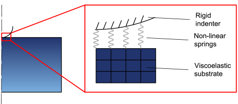
Figure 1 gives a graphical representation of the problem under investigation: a rigid hemisphere of radius is pressed into a viscoelastic half-space and then pulled apart from it. The normal driving velocity is assumed constant during the loading and unloading, being the contact penetration. Notice is measured at and corresponds to the normal displacement of the surface of the half-space with respect to its undeformed configuration (black dashed line). We denoted with and , the contact radius and applied load, respectively, which is assumed positive when compressive.

A standard linear solid is used to describe viscoelasticity in the half-space. Figure 2 shows the dependence of the viscoelastic modulus on the frequency . Specifically, Fig. 2a shows the variation with the dimensionless frequency of the real and imaginary parts of , while Fig. 2b the variation of the loss tangent with .


At low frequencies, the material is in the ‘rubbery’ region where the real part of the viscoelastic modulus is constant and the viscous dissipation related to the imaginary part is negligible (loss tangent ). At high frequencies, i.e., in the ‘glassy’ region, viscous dissipation is again negligible and the real part of is constant but much larger than in the ‘rubbery’ region. Viscous dissipation occurs at intermediate frequencies in the ‘transition’ region where the loss tangent takes non-zero values.
II.1 Numerical model
A Finite Element (FE) model (Fig. 3) has been developed to study the problem sketched in Fig. 1. The substrate has been modeled with axisymmetric plane elements with linear shape functions. Constraints are applied at the bottom boundary. For the rigid sphere we need to define only nodes on the surface where a single master node has been identified. On this node force and displacement are applied and its degree of freedoms are coupled with those of all other sphere nodes by simple constraint equations.
The adhesive interaction has been modeled by nonlinear spring elements with a traction-displacement relation according to the traction-gap law of Lennard-Jones (L-J)
| (1) |
Notice the compression (elongation) of the springs is the sum of the total ’rigid’ displacement of the sphere and the surface displacement of the deformable substrate
| (2) |
being the initial gap function, where is the assumed initial distance between the sphere and the substrate at .
This type of approach was already adopted in previous works (see, for example, Refs. Kadinetal2008 ; SongKomvo2011 ) to investigate similar problems with linear elastic and/or elasto-plastic materials.
As a result, the adhesive force exerted by a spring connected to a surface node at distance from the contact center is , except for the central node where we have .
The substrate has been modeled as a linear viscoelastic material. Specifically, a classical linear standard model was used with a single relaxation time and a Prony series representation was adopted
| (3) |
where is the elastic modulus at zero frequency and is the elastic modulus at high frequency.
The stress is calculated according to the following constitutive equation
| (4) |
where is the strain and the relaxation function.
To calculate stresses at time , the classical incremental finite element procedure has been used
| (5) |
Finally, the dissipated energy in the viscoelastic substrate is calculated as the energy required to deform the dashpot in the Maxwell element. Therefore, the increment of energy dissipated over a time increment is
| (6) |
where is the dashpot strain increment over time given by
| (7) |
being the Maxwell spring compliance.
The prepared code was solved with the aid of ANSYS solver.
III Results and Discussion
All results presented in this section are obtained for and and are given in terms of the following dimensionless quantities: , , , , and .
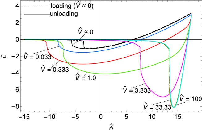
A first set of numerical simulations has been run at vanishing approaching velocity () to neglect time dependent effects during the loading phase. In this way, we are sure that the material is in a strain relaxed state at the end of loading and the following unloading phase always starts from the same initial conditions corresponding to the ‘rubbery’ region of Fig. 2. Figure 4 shows the resulting curves after a cycle of loading-unloading performed at different pulling velocities. Specifically, with reference to Fig. 4a, hysteresis dissipation (given by the difference between the work spent to bring the bodies in contact and that required to separate them) occurs even when the pulling velocity is negligible (i.e., in absence of viscous effects). In such case, energy loss (quantitatively given by the area between the loading and unloading curves) is exclusively due to the adhesive hysteresis related to the jumping-on and jumping-off phenomena (dotted lines identify the points where jump-on and jump-off instabilities occur). In this respect, Refs. Wangetal2021 ; ViolAff2021 have proposed a comprehensive investigation of the elastic adhesive hysteresis occurring between approach and retraction.
As expected, increasing the pulling velocity, dissipation increases and the unloading curves (coloured solid lines) more and more deviate from the loading one (dashed line). As a result, the pull-off force (i.e., the maximum tensile force) is observed to monotonically increase. It reaches a maximum value at about , after which it remains constant. Moreover, notice that at the highest velocities snap-off occurs at positive (compressive) penetrations because increasing the pulling velocity the time for the viscoelastic substrate to ‘relax’ and recovery its deformation reduces. As a result, the sphere imprint on the substrate can be clearly observed even when the sphere has been completely detached.
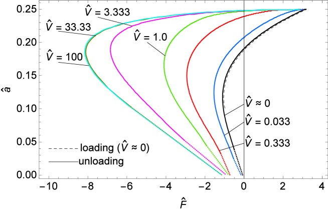
Figure 4b shows the dependence of the contact radius on the applied force during the loading and unloading simulations. In the present context, a rigorous definition of the contact radius can be disputable because Lennard-Jones force law imposes the gap between contacting surfaces is always nonzero. As observed by Feng in Ref. Feng2001 , where he investigated the adhesive contact between a rigid half-space and a deformable elastic sphere, the edge of the flattened area coincides well with the point where the tensile stress reaches its peak when the Tabor parameter . This agrees with previous observations of Greenwood Greenwood1997 who proposed to identify the edge of contact area at the point where the tensile stress takes its maximum value. However, for smaller , the edge of the contact area is less easily identified and seems to coincide with the point where the local Lennard-Jones pressure becomes zero Feng2001 . In our calculations, we find a perfect coincidence of the deformed profile of the substrate with that of the Hertzian rigid indenter up to the point where the tensile stress is maximum. Therefore, in the present calculations, the contact radius is identified as the radius at which the pressure takes its maximum tensile value. No perceptible difference between the curves can be identified for . Also, during the initial phase of unloading, the contact radius is practically constant. Such period (identified as stick time in Refs. Haiat2003 ; ViolanoPart1 ; ViolFront ) increases with the speed and reaches a maximum at about , above which no further variation is observed.
The pull-off process of a sphere from a substrate is analogous to the opening of a circular crack. In cracks propagation, viscoelastic dissipation is known to determine an increase in the propagation energy Schapery1975a ; Greenwood2004 ; PB2005 . It depends on the nature of the processes occurring in the crack-tip process zone, which is the region close to the crack tip where the classical Irwin equations Irwin1968 relating stresses to the distance from the crack tip are no longer valid.
It has been shown experimentally MB1980 ; GS1972 that depends on the crack tip velocity and the temperature according to
| (8) |
where is the Williams-Landel-Ferry (WLF) WLF1955 factor depending on the temperature and is the function of the viscoelastic energy dissipation in front of the crack tip. This function is characteristic of the viscoelastic material and is independent of the contact geometry (see MB1980 ).
In the literature, two different approaches have been developed for studying crack propagation in viscoelastic solids. The first approach is based on the cohesive-zone model, which assumes a constant stress in the process zone. Greenwood Greenwood2004 exploited a Maugis-Dugdale surface force law to find the dependence of the surface (propagation) energy on the crack tip velocity. For the standard linear solid used in our work, one obtains
| (9) |
where
| (10) |
and is the width of the process zone.
The second approach is instead based on energetic equilibrium. It was developed by Persson & Brenner (PB) PB2005 , who showed that the effective energy required to advance the crack tip by one unit area is related to the viscoelastic modulus and can be calculated theoretically as
| (11) |
where . In eq. (11), depends on the crack tip velocity and can be determined if one assumes that the stress at the crack tip takes some critical value necessary to break the atomic bonds for the tip to propagate. This gives
| (12) |
where is the crack tip radius for a very slowly moving crack and takes values of the order of the nanometer. Specifically, the crack tip cut-off radius in the Persson-Brener model is evaluated as , where is the characteristic stress necessary for bond breaking at the crack tip. Notice is not equivalent to in the cohesive-zone approach as instead erroneously assumed in recent papers ciava ; ciavaMcMeeking .
The mechanism regulating the contact opening occurring during the unloading phase in our numerical simulations is the same as the crack propagation at the interface between a viscoelastic solid and a rigid countersurface Persson2021 . Maugis & Barquins MB1980 and Charmet et al.Charmet1999 observed that viscoelastic losses are localized at the crack tip and bulk displacements are purely elastic. Therefore, a first estimate of the increase in the effective surface energy due to viscoelastic dissipation in the vicinity of the front of detachment can be done according to (see Lorenz2013 )
| (13) |
where is the pull-off force measured in the quasi-static limit ().
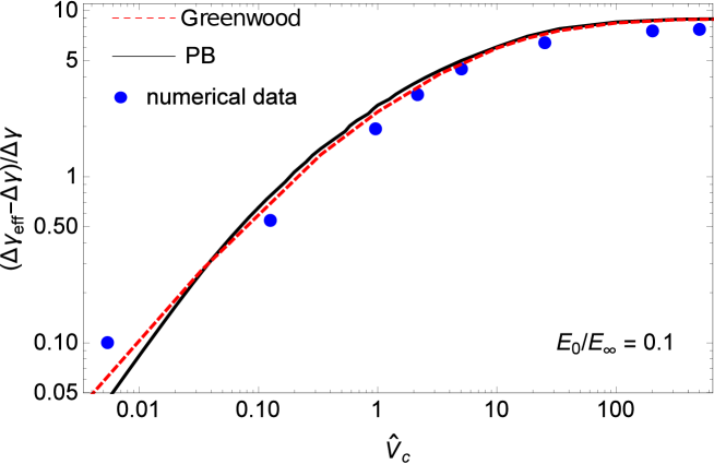
Figure 5 shows, in a double logarithmic plot, the relative increase of the effective surface energy in terms of the detachment front propagation velocity . Specifically, is estimated at pull-off (i.e., at the instant where the tensile force is maximum). Greenwood’s solution (red dashed line) and PB’s one (black solid line) are also shown as comparison. The first is obtained with equal to the maximum stress of Lennard-Jones law (), while the latter assuming (i.e., nm for nm).
As expected (see Refs. GreenJohn1981 ; Greenwood2004 ; PB2005 ), for high pulling velocities.
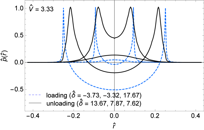
Figure 6 shows the contact pressure distribution on the contact region for different values of the approach . Dashed lines refer to the loading phase, while solid lines to the unloading one. The occurrence of positive tractions is clearly observable at the edges of the contact area when contact is established.
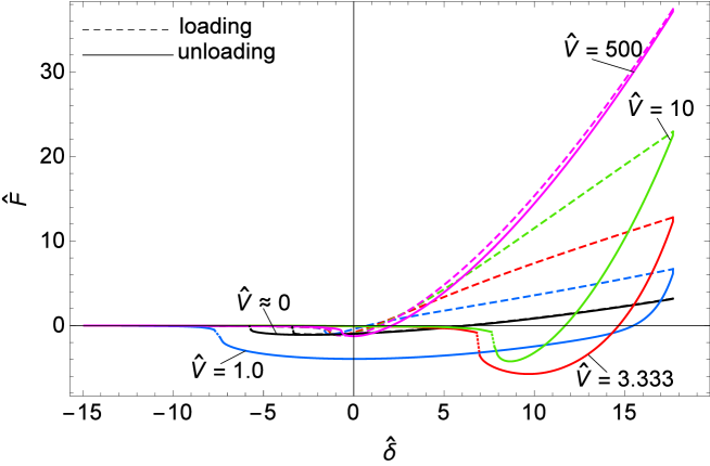
When the approximation of quasi-static loading is no longer valid and, hence, the material is not in a completely relaxed stress state at the beginning of unloading, the behaviour of the system significantly changes, as shown in Fig. 7. Here, loading and unloading are performed at the same driving velocity. Also, unloading starts right after the loading finishes so that the substrate material does not have the time to ‘relax’.
With reference to Fig. 7a, the small dissipation occurring at vanishing () and very high () velocities is exclusively due to the adhesive hysteresis related to jumping instabilities. The pull-off force first increases with the unloading speed, reaches a maximum and then reduces in a similar way to the hysteresis dissipation. This behaviour agrees with the viscoelastic modulus curves given in Fig. 2. In fact, only in the transition region we expect energy loss due to viscoelastic hysteresis. Therefore, at low and high speeds, i.e., low and high frequencies of excitation, the only dissipation is that related to the adhesion hysteresis due to the jump-on and jump-off instabilities. In this case, we can clearly identify the two regions where the material behaves elastically with modulus (low velocities) and (high velocities).
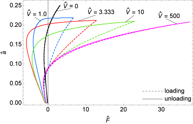
Figure 7b, instead, shows the contact radius, i.e., the radius where the contact pressure takes its tensile peak, in terms of the applied force. No difference can be identified between the loading and unloading curves at and as the substrate material behaves elastically. However, at high velocities the system is much stiffer, and the same contact area is reached at much larger forces. Moreover, in the regions where the material is ‘elastic’ (rubbery and glassy regions) the contact radius significantly decreases right from the early stages of unloading. On the contrary, at intermediate driving velocities, we observe an initial phase where the behaviour of the contact radius is more similar to that observed in Fig. 4b.
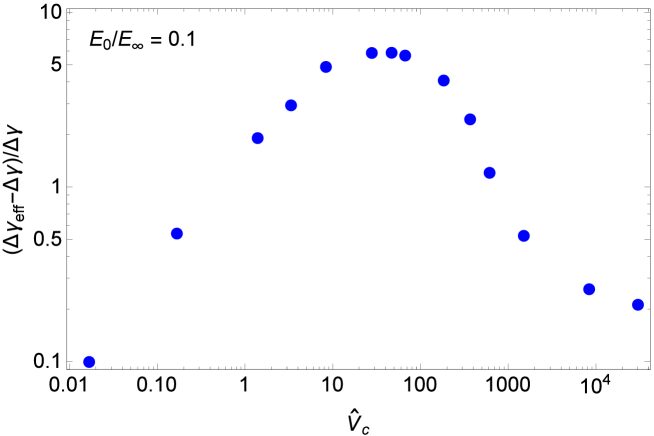
Figure 8 shows the relative increase of the effective surface energy in terms of the contact line velocity as obtained from numerical simulations performed at different driving velocities . As above explained, is estimated at pull-off when we reach the maximum tensile force. Results are quite different with respect to Fig. 4. Indeed, after reaching a maximum value, reduces when moving towards high contact line velocities A bell-shape curve for the effective surface energy has been also found in Ref. Lin2002 by numerical simulations on two contacting viscoelastic spheres and in Ref. Gustavo with classical JKR-like experiments.
The velocity where takes its largest value does not correspond to the frequency at which the loss tangent is maximum. In fact, the frequency of excitation can be roughly estimated as and the peak of is reached at about . Therefore, at pull-off being the contact radius , the frequency of excitation can be estimated as , which falls in the transition region but is not however close to the value where the loss tangent peak occurs (see Fig. 2b). A similar result is reported in Ref. francesi , where the fracture energy is found to reach its maximum value for low speeds ”even if the ’liquid zone’ has not emerged yet”.
Furthermore, in agreement with the considerations done in Ref. Israelachvili and the calculations performed in Ref. Lin2002 , we observe that the maximum dissipation occurs at velocity at which the time of observation (or time scale of the process) is comparable to the characteristic time . Therefore, the peak of is expected to occur close to , where
| (14) |
is the so-called Deborah number Reiner1964 . Indeed, we find when the interaction time is estimated as the time between jump-on and jump-off phenomena.
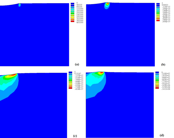
The different behaviour observed in Figs. 4 and 7, can find a possible explanation in results shown in Fig. 9, where the accumulated dissipated energy density is plotted at different times (at the initial phase of unloading and at pull-off). Specifically, in Fig. 9a-b, loading is carried out under quasi-static conditions () and unloading at pulling velocity , while in Fig. 9c-d loading and unloading are performed at the same . As expected, in the first case, dissipation mainly occurs at the interface, near the front of detachment. Here, therefore, the classical Gent&Schultz assumption of considering viscous effects localized exclusively close to the crack tip is reasonably satisfied. In the latter case, we notice that this assumption fails as dissipation basically occurs in the bulk.
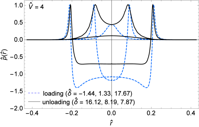
Finally, Fig. 10 shows the contact pressure distribution in different instants of the loading-unloading cycle. Again, tractions at the edges of the contact area arise when contact is established. Moreover, we observe that, at high penetrations, the pressure on the compressive contact region is roughly constant.
IV Conclusions
In this paper, we have presented a fully deterministic numerical model for studying the adhesive normal contact between a rigid sphere and a viscoelastic substrate. Van der Waals adhesive interactions are described by means of non-linear springs with a traction-gap relation according to the Lennard-Jones law, while material viscoelasticity is modeled by a standard linear solid with a spring in parallel with a Maxwell element constituted by a spring in series with a dashpot.
In a first set of simulations, we have imposed quasi-static loading conditions () to ensure adhesive equilibrium and negligible viscous effects. In such case, the material behaves as a soft elastic medium (rubbery region). Unloading has been instead performed for different driving velocities. We found that, as unloading starts from a completely relaxed state of the material, a progressive enhancement of the effective surface energy with the contact line velocity is found up to an asymptotic value. This is reached for high contact line velocities that correspond to excitation frequencies falling in the glassy region of the material, where it behaves as a stiff elastic medium. Numerical data of are found in good agreement with the theoretical predictions of two crack’s propagation theories, namely the cohesive-zone model proposed by Greenwood Greenwood2004 on the basis of Schapery’s findings, and the energetic approach developed by Persson & Brenner PB2005 .
In a second set of simulations, we have performed loading and unloading at the same driving velocity. No dwell time has been waited before unloading. In such case, the trend of the effective surface energy with the contact line velocity is described by a bell-shaped function. The maximum of the bell is found for exciting frequency lower than the frequency that maximize the tangent loss of the viscoelastic modulus in agreement to previous studies. Moreover, the peak of dissipation is found close to . We have also discussed how the Gent&Schultz assumption works in this case showing that viscous dissipation is not always localized along the contact perimeter but it may occur in the bulk material. In such case, adhesion models based on linear elastic fracture mechanics are expected to be less accurate.
Acknowledgements.
L.A. and G.V. acknowledge support from the Italian Ministry of Education, University and Research (MIUR) under the program ”Departments of Excellence” (L.232/2016). Moreover, this work was supported by the project ”FASTire (Foam Airless Spoked Tire): Smart Airless Tyres for Extremely-Low Rolling Resistance and Superior Passengers Comfort” funded by the Italian MIUR Progetti di Ricerca di Rilevante Interesse Nazionale (PRIN) call 2017—grant n. 2017948FEN.References
- (1) Jeong, Jae-Woong, Gunchul Shin, Sung Il Park, Ki Jun Yu, Lizhi Xu, and John A. Rogers. (2015). Soft materials in neuroengineering for hard problems in neuroscience. Neuron 86(1), 175-186.
- (2) Shintake, J., Cacucciolo, V., Floreano, D., & Shea, H. (2018). Soft robotic grippers. Advanced Materials, 30(29), 1707035.
- (3) Yao, H., Yang, W., Cheng, W., Tan, Y. J., See, H. H., Li, S., … & Tee, B. C. (2020). Near–hysteresis-free soft tactile electronic skins for wearables and reliable machine learning. Proceedings of the National Academy of Sciences, 117(41), 25352-25359.
- (4) Villey, R., Creton, C., Cortet, P. P., Dalbe, M. J., Jet, T., Saintyves, B., … & Ciccotti, M. (2015). Rate-dependent elastic hysteresis during the peeling of pressure sensitive adhesives. Soft Matter, 11(17), 3480-3491.
- (5) Meitl, M. A., Zhu, Z. T., Kumar, V., Lee, K. J., Feng, X., Huang, Y. Y., … & Rogers, J. A. (2006). Transfer printing by kinetic control of adhesion to an elastomeric stamp. Nature materials, 5(1), 33-38.
- (6) Violano, G., Chateauminois, A., & Afferrante, L. (2021). Rate-dependent adhesion of viscoelastic contacts, Part I: Contact area and contact line velocity within model randomly rough surfaces. Mechanics of Materials, 103926.
- (7) Violano, G., Chateauminois, A., & Afferrante, L. (2021). Rate-dependent adhesion of viscoelastic contacts. Part II: Numerical model and hysteresis dissipation. Mechanics of Materials, 158, 103884.
- (8) Lee, E. H., & Radok, J. R. M. (1960). The contact problem for viscoelastic bodies. Journal ofApplied Mechanics – Transactions of the ASME 1960;27:438–44
- (9) Ting, T. C. T. (1966). The contact stresses between a rigid indenter and a viscoelastic half-space. J. Appl. Mech. 33, 845.
- (10) Greenwood, J. A. (2010). Contact between an axisymmetric indenter and a viscoelastic half-space. International Journal of Mechanical Sciences, 52(6), 829-835.
- (11) Johnson, K. L., Kendall, K., & Roberts, A. (1971). Surface energy and the contact of elastic solids. Proceedings of the royal society of London. A. mathematical and physical sciences, 324(1558), 301-313.
- (12) Derjaguin, B. V., Muller, V. M., & Toporov, Y. P. (1975). Effect of contact deformations on the adhesion of particles. Journal of Colloid and interface science, 53(2), 314-326.
- (13) Tabor, D. (1977). Surface forces and surface interactions. J. Colloids Interface Sci. 58, 2.
- (14) Maugis, D. (1992). Adhesion of spheres: the JKR-DMT transition using a Dugdale model. Journal of colloid and interface science, 150(1), 243-269.
- (15) Dugdale, D. S. (1960). Yielding of steel sheets containing slits. Journal of the Mechanics and Physics of Solids, 8(2), 100-104.
- (16) Maugis, D., & Barquins, M. (1980). Fracture mechanics and adherence of viscoelastic solids. In Adhesion and adsorption of polymers (pp. 203-277). Springer, Boston, MA.
- (17) Greenwood, J. A., & Johnson, K. L. (1981). The mechanics of adhesion of viscoelastic solids. Philosophical Magazine A, 43(3), 697-711.
- (18) Muller, V. M. (1999). On the theory of pull-off of a viscoelastic sphere from a flat surface. Journal of Adhesion Science and Technology, 13(9), 999-1016.
- (19) Gent, A. N., & Schultz, J. (1972). Effect of wetting liquids on the strength of adhesion of viscoelastic material. The Journal of Adhesion, 3(4), 281-294.
- (20) Schapery, R. A. (1975). A theory of crack initiation and growth in viscoelastic media. International Journal of fracture, 11(1), 141-159.
- (21) Haiat, G., Huy, M. P., & Barthel, E. (2003). The adhesive contact of viscoelastic spheres. Journal of the Mechanics and Physics of Solids, 51(1), 69-99.
- (22) Greenwood, J.A. & Johnson, K.L. (1998). An alternative to the Maugis model of adhesion between elastic spheres. J. Phys. D Appl. Phys. 31, 3279–3290.
- (23) Lin, Y. Y., & Hui, C. Y. (2002). Mechanics of contact and adhesion between viscoelastic spheres: An analysis of hysteresis during loading and unloading. Journal of Polymer Science Part B: Polymer Physics, 40(9), 772-793.
- (24) Barthel, E. & Frétigny, C. (2009). Adhesive contact of elastomers: effective adhesion energy and creep function. Journal of Physics D: Applied Physics, 42, 195302.
- (25) Campana, C. & Müuser, M.H. (2006). Practical Green’s function approach to the simulation of elastic semi-infinite solids. Phys. Rev. B, 74, 075420.
- (26) Sukhomlinov, S. & Müuser, M.H. (2021). On the viscous dissipation caused by randomly rough indenters in smooth sliding motion. arXiv:2104.15056v2
- (27) Greenwood, J. A. (2004). The theory of viscoelastic crack propagation and healing. Journal of Physics D: Applied Physics, 37(18), 2557.
- (28) Persson, B. N. J., & Brener, E. A. (2005). Crack propagation in viscoelastic solids. Physical Review E, 71(3), 036123.
- (29) Kadin, Y., Kligerman, Y., & Etsion, I. (2008). Loading–unloading of an elastic–plastic adhesive spherical microcontact. Journal of Colloid and Interface Science, 321(1), 242-250.
- (30) Song, Z., & Komvopoulos, K. (2011). Adhesion-induced instabilities in elastic and elastic–plastic contacts during single and repetitive normal loading. Journal of the Mechanics and Physics of Solids, 59(4), 884-897.
- (31) Wang, A., Zhou, Y., & Müser, M. H. (2021). Modeling Adhesive Hysteresis. Lubricants, 9(2), 17.
- (32) Violano, G., & Afferrante, L. (2021). Roughness-Induced Adhesive Hysteresis in Self-Affine Fractal Surfaces. Lubricants, 9(1), 7.
- (33) Feng, J. Q. (2001). Adhesive contact of elastically deformable spheres: a computational study of pull-off force and contact radius. Journal of colloid and interface science, 238(2), 318-323.
- (34) Greenwood, J. A. (1997). Adhesion of elastic spheres. Proceedings of the Royal Society of London. Series A: Mathematical, Physical and Engineering Sciences, 453(1961), 1277-1297.
- (35) Violano, G., Chateauminois, A., & Afferrante, L. (2021). A JKR-like solution for viscoelastic adhesive contacts. Frontiers in Mechanical Engineering, 7, 25.
- (36) Irwin, G. R. (1968). Linear fracture mechanics, fracture transition, and fracture control. Engineering fracture mechanics, 1(2), 241-257.
- (37) Williams, M. L., Landel, R. F., & Ferry, J. D. (1955). The temperature dependence of relaxation mechanisms in amorphous polymers and other glass-forming liquids. Journal of the American Chemical society, 77(14), 3701-3707.
- (38) M. Ciavarella, A comparison of Gent-Schultz law with cohesive models of viscoelastic subcritical crack propagation, Prepring (2021), see: https://www.researchgate.net/publication/35032525.
- (39) M. Ciavarella and R. Mcmeeking, Exact solutions to the viscoelastic crack problem with power law creep compliance materials, and comparison with the Schapery and Persson-Brener approximate solutions, Prepring (2021), see: https://www.researchgate.net/publication/350431355.
- (40) Persson, B. N. J. (2021). A simple model for viscoelastic crack propagation. The European Physical Journal E, 44(1), 1-10.
- (41) Charmet, J. C., Vallet, D., and Barquins, M. (1999). “Chapter 3: Surface and bulk properties in adherence of elastic-viscoelastic solids,” in Microstructure and Microtribology of Polymer Surfaces, eds V. V. Tsukruk and K. J.Wahl (American Chemical Society). doi: 10.1021/bk-2000-074
- (42) Lorenz, B., Krick, B. A., Mulakaluri, N., Smolyakova, M., Dieluweit, S., Sawyer, W. G., & Persson, B. N. J. (2013). Adhesion: role of bulk viscoelasticity and surface roughness. Journal of Physics: Condensed Matter, 25(22), 225004.
- (43) Gustavo, L-, Jianmei, P., Manfred, H., & Israelachvili, J.N., (1998). Temperature and Time Effects on the “Adhesion Dynamics” of Poly(butyl methacrylate) (PBMA) Surfaces. Langmuir, 14, 3873-3881.
- (44) Saulnier, F., Ondarcüuhu, T., Aradian, A., & Raphaël, E. (2004). Adhesion between a Viscoelastic Material and a Solid Surface. Macromolecules, 37, 1067-1075.
- (45) Israelachvili, J.N., & Berman, A., (1995). Irreversibility, Energy Dissipation, and Time Effects in Intermolecular and Surface Interactions, Israel Journal of Chemistry, 35, 85-91.
- (46) Reiner, M., (1964). The Deborah number. Phys. Today., 17(1), 62