Spin-orbit pumping
Abstract
We study theoretically the effect of a rotating electric field on a diffusive nanowire and find an effect that is analogous to spin pumping, which refers to the generation of spin through a rotating magnetic field. The electron spin couples to the electric field because the particle motion induces an effective magnetic field in its rest frame. In a diffusive system the velocity of the particle, and therefore also its effective magnetic field, rapidly and randomly changes direction. Nevertheless, we demonstrate analytically and via a physical argument why the combination of the two effects described above produces a finite magnetization along the axis of rotation. This manifests as a measurable spin-voltage in the range of tens of microvolts.
Introduction. As further miniaturization of transistors becomes ever more difficult Kaul (2017), there is a pressing need for new technologies to aid or replace silicon-based information technology. Spintronics is a candidate which has as its underlying idea to use the electron spin as an information carrier Bader and Parkin (2010); Hirohata et al. (2020). This idea is promising because the spin degrees of freedom in solid state systems can potentially be manipulated in a highly energy-efficient manner. This is important since the growing need for more computing power has significantly increased the energy consumption of information and communication technologies Puebla et al. (2020); Jones (2018). As a result, the study of spin transport and spin manipulation in low-dimensional and nanoscale devices is a growing field of research.
One important aspect of spin manipulation is the generation of spin, which can be done by so-called spin pumping Tserkovnyak et al. (2002, 2005). This refers to the generation of spin through a precessing magnetic field. After its discovery in ferromagnets Tserkovnyak et al. (2002), spin pumping has been studied for a wide range of systems, such as antiferromagnets Cheng et al. (2014); Johansen and Brataas (2017); Vaidya et al. (2020), spin-glass systems Fujimoto et al. (2020) and superconducting hybrid structures Jeon et al. (2018); Kato et al. (2019); Fyhn and Linder (2021a). Since the electron spin gives rise to a magnetic dipole moment, it is conceptually simplest to manipulate through magnetic fields. However, spin also couple to electric fields since, from the perspective of a moving electron, an electric field gives rise to an effective magnetic field. This interaction between spin and electric fields is known as spin-orbit coupling (SOC), and is the reason why electric fields play a central role in spintronics research Manchon et al. (2019, 2015). In this manuscript we investigate whether an effect analogous to spin pumping can be obtained from a time-dependent electric field through SOC.
Materials with SOC are most famously able to produce spin polarization through the spin Hall effect Sinova et al. (2015). This refers to how spin accumulates when a charge current is passed through, because the trajectories of electrons with opposite spins are bent in opposite directions. This can produce a measurable spin polarization Kato et al. (2004); Garlid et al. (2006, 2010), but unlike spin pumping it requires an applied electric current. The spin Hall effect is also widely used to detect the spin-currents produced by spin pumping Sinova et al. (2015); Vaidya et al. (2020); Mosendz et al. (2010).
The prospect of spin manipulation from external electric fields is especially interesting in the context of spin-based quantum bits. This is because magnetic fields are difficult to localize Simovi et al. (2006); Torrezan et al. (2009); Koppens et al. (442) compared to their electric counterparts Nowack et al. (2007); Liang and Gao (2012), something which makes individual control of spin-based quantum bits more feasible with electric fields. Time-dependent SOC has therefore mostly been considered in quantum dots and quantum wells. In such structures, oscillating electric fields has been studied experimentally Kato et al. (2003); Nowack et al. (2007) and theoretically Rashba and Efros (2003); Venitucci et al. (2018); Michal et al. (2021); Efros and Rashba (2006) with a fixed direction in space. However, a harmonically oscillating electric field with fixed direction does not by itself break time reversal symmetry, which is necessary in order to produce magnetization. These systems therefore require an additional static magnetic field, but an entirely electric control of the spin motion can be obtained by a rotating electric field. This was pointed out by Serebrennikov (2004), who considered an electron in a spherical potential under the influence of a rotating electric field. More recently, Entin-Wohlman et al. (2020) showed that when a quantum dot subjected to a rotating electric field is placed in a junction with normal metals, the resulting time-dependent tunneling can induce a nonzero magnetization in the leads.
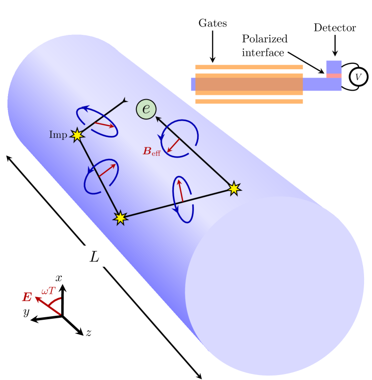
The prospect of spin-generation from purely electric fields from local gate electrodes is attractive also from a spintronics perspective, since such devices could be placed in close proximity to other nanoscale devices without them being affected by undesirable stray fields. For this reason, and motivated by the success of electrical control of spin dynamics in quantum dots, we present here a study of how magnetization can be induced in diffusive nanowires by purely electrical means. We consider an insulated wire subjected to a rotating electric field, as depicted in Fig. 1.
In diffusive systems the physical picture is complicated by the fact that the particles rapidly change momentum direction. This means that the effective magnetic fields also change direction frequently, as viewed from the rest frame of the particles. Nevertheless, we find using quasiclassical Keldysh theory that a finite, time-independent magnetization is induced along the axis of rotation. After presenting our results, we explain the physical origin of this effect. Hence, pumping spin by rotating electric fields, which we here refer to as spin-orbit pumping, or SO pumping, can be used as an alternative to conventional spin pumping.
Systems with strong atomic SOC would be advantageous in order to realize spin-orbit pumping experimentally. The SOC in such system can, depending on the lattice symmetry, have additional static terms. These terms will not induce spin-orbit pumping by themselves, but they can nevertheless affect the results. We do not include such terms here, but note that it would be interesting for future work to study how the inclusion of other types of SOC can affect spin-orbit pumping.
Equations. Under the assumption that the Fermi energy is the dominant energy scale and the mean free path is short, the system illustrated in Fig. 1 can be described by the quasiclassical Keldysh theory Belzig et al. (1999); Rammer and Smith (1986); Eilenberger (1968). Moreover, if the mean free path is much shorter than system length and the length scale associated with SOC, , and the elastic scattering rate is much shorter than the angular frequency of the rotating electric field, the system can be classified as diffusive. In this case the quasiclassical Green’s function solves the Usadel equation Usadel (1970); Rammer and Smith (1986),
| (1) |
Here, is time, is the diffusion constant, is the self-energy matrix from inelastic relaxation processes Virtanen et al. (2010) and is the covariant derivative which includes the spin-orbit coupling. Moreover, the circle-product is
| (2) |
where is energy. The time-varying electric field will generally also induce a magnetic field, but we find that this is negligible compared to the effective magnetic field felt by the moving particles due to the electric field.
The circle-product makes the Usadel equation difficult to solve in time-dependent situations, but in this case it can be simplified by a Fourier transform in energy Fyhn and Linder (2021b). From this we can find an equation for the magnetization,
| (3) |
where the superscript denotes the Keldysh part, is the vector of Pauli matrices, is the Landé -factor, is the density of states at the Fermi energy, is the Bohr magneton. We find that solves
| (4) |
as shown in the supplementary material sup ; Houzet (2008). Here, comes from the spin-orbit coupling and is given by
| (5) |
where is the Rashba coupling, is the effective mass, is the unit vector in the -direction and is the unit vector pointing in the direction of the electric field, which has been assumed to be uniform in space. Finally, is an effective parameter describing the spin relaxation rate from sources other than spin-orbit coupling, such as inelastic phonon scattering. The spin relaxation rate described by is assumed independent of spin-direction. Moreover, Eq. 5 already contains a relaxation term that depends on the spin-direction due to which we comment on below.
The left hand side of Eq. 4 describes diffusion and the spin relaxation in the absence of SOC, while the right hand side is the effect of the SOC. The first term on the right side describes spin precession of the diffusion current and the second term is spin relaxation due to the Dyakonov-Perel mechanism Dyakonov and Perel (1972). This relaxation comes from the randomization of spin precession angles caused by elastic scattering at non-magnetic impurities. The third and final term is the source term coming from the time-dependence of . It is this term which makes SOC capable of producing spin in diffusive systems. We can from this term immediately see that a time-varying electric field with fixed direction will not generate spin, since in that case.
Equation 4 must be accompanied by boundary conditions. For simplicity we choose insulating boundaries, which means that the particle flux across the interfaces at and must be zero. In the diffusive limit of the quasiclassical Green’s function formalism, the relevant boundary condition is known as the Kupriyanov-Lukichev boundary condition Kupriyanov and Lukichev (1988). From this we find that
| (6) |
at and , as shown in the supplementary material sup ; Chandrasekhar (2008); Ouassou et al. (2018).
Equation 4 can be solved for times long after the rotating electric field has been turned on by looking for a stationary solution in the rotating reference frame. This is because all solutions converge to this unique stationary solution, as we prove in the supplementary material sup . In the rotating reference frame, the electric field is time-independent and the magnetization along the -direction is the same as in the lab frame. Converting the equations into the rotating frame can be done by inserting the rotation matrix which satisfies
| (7) |
where is constant in time. We choose . To write Eq. 4 in the rotating system, we write and use the relations and
| (8) |
The equation for the magnetization in the rotating frame is therefore
| (9) |
where we have used that is independent of time and . The boundary condition in the rotating frame is
| (10) |
at and .
The magnetization is measurable through the so-called spin-voltage,
| (11) |
If we connect the nanowire to a detector electrode through an interface with polarization along the -direction, as illustrated in Fig. 1, then is the voltage difference between the nanowire and ferromagnet in the absence of electric current Silsbee (1980); Johnson and Silsbee (1985); Tombros et al. (2007); Poli et al. (2008); Silaev et al. (2015); Heikkilä et al. (2019). This is shown in the supplementary material sup ; Bergeret et al. (2012); Ouassou et al. (2017); Hugdal et al. (2017).
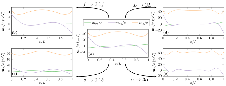
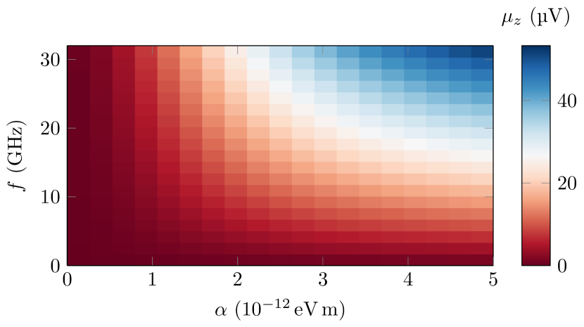
Results. We solve Eqs. 9 and 10 numerically by using the finite element method. Figure 2 shows the resulting spatial distribution of for various system parameters and Fig. 3 shows the spatially averaged spin-voltage as a function of the Rashba coupling parameter and frequency, . We have used , where is the electron mass and . Note that the -component of the magnetization is equal in the rotating frame and lab-frame, so in Fig. 2 is static and equal in both frames.
Figure 2 shows that the magnetization has non-zero components in the - and -direction that are antisymmetric around the middle of the wire. In the rotating frame, magnetization along the -direction is induced at the boundaries, as can be seen from Eq. 10. This magnetization is rotated around the -axis from the term in Eq. 9, and it is rotated into the -component because of . The former comes from the effective magnetic field present in the rotating frame and the latter is the spin precession of the diffusion current from SOC. We can see the spin rotation effect of by comparing panels (a) and (b) in Fig. 2. From this we see that when is decreased from to , and are also scaled by a factor . This is reasonable since the source term in the magnetization equation is proportional to . The -component, , on the other hand, is reduced much more in Fig. 2 (b), which is expected since the rotation from , coming from the term , is much less.
Comparing Fig. 2 (a) to Fig. 2 (c) and (e) shows the effect of decreasing the inelastic relaxation and increasing the Rashba coupling, respectively. In both cases the ratio between the spin generation from SOC and the inelastic spin relaxation is increased. As a result, the magnetization along the -axis is increased. From Eq. 10 we see gets smaller at the boundaries when is larger. This is reflected in the smaller -component in Fig. 2 (c) and (e). Finally, unlike Fig. 2 (c), Fig. 2 (e) has more rapid oscillations in and . This is expected since increasing not only increases the spin generation, but also the spin precession associated with SOC.
From Figs. 2 and 3 we see that the rotating electric field can produce a spin-voltage of tens of microvolt with the parameters used here. This is our main result and shows that spin-orbit pumping is be capable of producing a measurable magnetization. We propose that the SO pumping effect can be understood in terms of normal spin pumping from the effective magnetic field in the reference frames of the moving charge carriers. Consider a particle with velocity moving in the effective electric field . The effective magnetic field is obtained via a Lorentz-transformation:
| (12) |
This effective field rotates in an elliptical way around an axis. Although the direction of this axis changes with the particle velocity, its component along the -axis is always of the same sign. This is illustrated in Fig. 1 and can be most easily seen by noting that the projection of onto the -plane always rotates counter-clockwise when and clockwise when . Since it is known from normal spin pumping that a rotating magnetic field induces a magnetization along the axis of rotation, this explains why a rotating electric field can generate a magnetization in the -direction. Summarized, the physical picture of SO pumping in diffusive systems is as follows. With each elastic scattering, the spin precession axis jumps to a new direction. This randomizes the spin over time and gives rise to a spin relaxation. This is just the normal Dyakonov-Perel mechanism. However, since the electric field rotates, the spin precession axis also rotates between scatterings. Since this rotation is always in the same direction around the -axis it gives rise to a net spin-accumulation polarized in the -direction. The equivalence in the quasiclassical theory between SOC and the effective magnetic field is shown explicitly in the supplementary material sup .
One difference from normal spin pumping is that a rotating electric field both generate and dissipate spin because of the Dyakonov-Perel mechanism. Thus, by increasing the electric field strength, both spin generation and spin relaxation is increased. When Dyakonov-Perel relaxation is the dominant spin relaxation mechanism, we can see from Eqs. 9 and 10 that the spin generation and spin relaxation mechanisms equalize when . This can be seen from the fact that solves Eqs. 9 and 10 when . Thus, SO pumping in diffusive systems can at most produce as spin-voltage of . However, in the presence of other spin relaxation mechanisms, the observed spin-voltage will be less, as is the case in Figs. 2 and 3.
Based on the physical picture of SO pumping as the cumulative effect of normal spin pumping from the rotating effective magnetic field observed between each scattering, it is clear that scattering processes work to reduce the SO pumping effect. It would therefore be of interest to study rotating electric fields in clean, ballistic systems to see if the SO pumping effect can be enhanced in such systems. We leave this for future work.
Conclusion. We have found using quasiclassical Keldysh theory that a rotating electric field can induce a magnetization and a measurable spin-voltage of tens of . This spin-orbit pumping can be understood as a spin pumping from the effective magnetic field in the rest frame of the moving particles. This is because, despite the jumps occurring at each scattering event, the projection of the effective magnetic field onto the plane in which the electric field is applied always rotates in the same direction. Obtaining a spin-voltage above with the material parameters used here requires a Rashba coupling of . Rashba coupling strengths of this magnitude has been obtained experimentally at temperatures below in nanowires with applied electric fields Liang and Gao (2012); Takase et al. (2017). One reason for this requirement is that spin relaxation, both from inelastic relaxation and from SOC through Dyakonov-Perel relaxation, inhibits spin-orbit pumping. Thus, it would be of interest to study rotating electric fields in clean, ballistic nanowires to see whether the spin-orbit pumping effect is stronger in such systems. Nevertheless, the findings presented here shows that spin-orbit pumping should be capable of producing an experimentally observable magnetization even in diffusive systems.
Acknowledgements.
This work was supported by the Research Council of Norway through grant 240806, and its Centres of Excellence funding scheme grant 262633 “QuSpin”. J. L. also acknowledge funding from the NV-faculty at the Norwegian University of Science and Technology.References
- Kaul (2017) A. Kaul, Microelectronics to Nanoelectronics: Materials, Devices & Manufacturability (CRC Press, 2017).
- Bader and Parkin (2010) S. Bader and S. Parkin, Annu. Rev. Condens. Matter Phys. 1, 71 (2010).
- Hirohata et al. (2020) A. Hirohata, K. Yamada, Y. Nakatani, I.-L. Prejbeanu, B. Diény, P. Pirro, and B. Hillebrands, J. Magn. Magn. Mater. 509, 166711 (2020).
- Puebla et al. (2020) J. Puebla, J. Kim, K. Kondou, and Y. Otani, Commun. Mater. 1, 24 (2020).
- Jones (2018) N. Jones, Nature 561, 163 (2018).
- Tserkovnyak et al. (2002) Y. Tserkovnyak, A. Brataas, and G. E. W. Bauer, Phys. Rev. Lett. 88, 117601 (2002).
- Tserkovnyak et al. (2005) Y. Tserkovnyak, A. Brataas, G. E. W. Bauer, and B. I. Halperin, Rev. Mod. Phys. 77, 1375 (2005).
- Cheng et al. (2014) R. Cheng, J. Xiao, Q. Niu, and A. Brataas, Phys. Rev. Lett. 113, 057601 (2014).
- Johansen and Brataas (2017) O. Johansen and A. Brataas, Phys. Rev. B 95, 220408(R) (2017).
- Vaidya et al. (2020) P. Vaidya, S. A. Morley, J. van Tol, Y. Liu, R. Cheng, A. Brataas, D. Lederman, and E. del Barco, Science 368, 160 (2020).
- Fujimoto et al. (2020) Y. Fujimoto, M. Ichioka, and H. Adachi, Phys. Rev. B 101, 184412 (2020).
- Jeon et al. (2018) K.-R. Jeon, C. Ciccarelli, H. Kurebayashi, J. Wunderlich, L. F. Cohen, S. Komori, J. W. A. Robinson, and M. G. Blamire, Phys. Rev. Applied 10, 014029 (2018).
- Kato et al. (2019) T. Kato, Y. Ohnuma, M. Matsuo, J. Rech, T. Jonckheere, and T. Martin, Phys. Rev. B 99, 144411 (2019).
- Fyhn and Linder (2021a) E. H. Fyhn and J. Linder, Phys. Rev. B 103, 134508 (2021a).
- Manchon et al. (2019) A. Manchon, J. Zelezný, I. M. Miron, T. Jungwirth, J. Sinova, A. Thiaville, K. Garello, and P. Gambardella, Rev. Mod. Phys. 91, 035004 (2019).
- Manchon et al. (2015) A. Manchon, H. C. Koo, J. Nitta, S. M. Frolov, and R. A. Duine, Nat. Mater. 14, 871 (2015).
- Sinova et al. (2015) J. Sinova, S. O. Valenzuela, J. Wunderlich, C. H. Back, and T. Jungwirth, Rev. Mod. Phys. 87, 1213 (2015).
- Kato et al. (2004) Y. K. Kato, R. C. Myers, A. C. Gossard, and D. D. Awschalom, Science 306, 1910 (2004).
- Garlid et al. (2006) E. S. Garlid, Q. O. Hu, M. K. Chan, C. J. Palmstrøm, and P. A. Crowell, Nature 442, 176 (2006).
- Garlid et al. (2010) E. S. Garlid, Q. O. Hu, M. K. Chan, C. J. Palmstrøm, and P. A. Crowell, Phys. Rev. Lett. 105, 156602 (2010).
- Mosendz et al. (2010) O. Mosendz, J. E. Pearson, F. Y. Fradin, G. E. W. Bauer, S. D. Bader, and A. Hoffmann, Phys. Rev. Lett. 104, 046601 (2010).
- Simovi et al. (2006) B. Simovi, P. Studerus, S. Gustavsson, R. Leturcq, K. Ensslin, R. Schuhmann, J. Forrer, and A. Schweiger, Rev. Sci. Instrum. 77, 064702 (2006).
- Torrezan et al. (2009) A. C. Torrezan, T. P. Mayer Alegre, and G. Medeiros-Ribeiro, Rev. Sci. Instrum. 80, 075111 (2009).
- Koppens et al. (442) F. H. L. Koppens, C. Buizert, K. J. Tielrooij, I. T. Vink, K. C. Nowack, T. Meunier, L. P. Kouwenhoven, and L. M. K. Vandersypen, Nature 442, 766 (442).
- Nowack et al. (2007) K. C. Nowack, F. H. L. Koppens, Y. V. Nazarov, and L. M. K. Vandersypen, Science 318, 1430 (2007).
- Liang and Gao (2012) D. Liang and X. P. Gao, Nano Lett. 12, 3263 (2012).
- Kato et al. (2003) Y. Kato, R. C. Myers, D. C. Driscoll, A. C. Gossard, J. Levy, and D. D. Awschalom, Science 299, 1201 (2003).
- Rashba and Efros (2003) E. I. Rashba and A. L. Efros, Phys. Rev. Lett. 91, 126405 (2003).
- Venitucci et al. (2018) B. Venitucci, L. Bourdet, D. Pouzada, and Y.-M. Niquet, Phys. Rev. B 98, 155319 (2018).
- Michal et al. (2021) V. P. Michal, B. Venitucci, and Y.-M. Niquet, Phys. Rev. B 103, 045305 (2021).
- Efros and Rashba (2006) A. L. Efros and E. I. Rashba, Phys. Rev. B 73, 165325 (2006).
- Serebrennikov (2004) Y. A. Serebrennikov, Phys. Rev. B 70, 064422 (2004).
- Entin-Wohlman et al. (2020) O. Entin-Wohlman, R. I. Shekhter, M. Jonson, and A. Aharony, Phys. Rev. B 102, 075419 (2020).
- Belzig et al. (1999) W. Belzig, F. K. Wilhelm, C. Bruder, G. Schön, and A. D. Zaikin, Superlattices Microstruct. 25, 1251 (1999).
- Rammer and Smith (1986) J. Rammer and H. Smith, Rev. Mod. Phys. 58, 323 (1986).
- Eilenberger (1968) G. Eilenberger, Z. Physik 214, 195 (1968).
- Usadel (1970) K. D. Usadel, Phys. Rev. Lett. 25, 507 (1970).
- Virtanen et al. (2010) P. Virtanen, T. T. Heikkilä, F. S. Bergeret, and J. C. Cuevas, Phys. Rev. Lett. 104, 247003 (2010).
- Fyhn and Linder (2021b) E. H. Fyhn and J. Linder, Phys. Rev. B 103, L100502 (2021b).
- (40) See Supplemental Material at [URL to be inserted] for a derivation of the equations.
- Houzet (2008) M. Houzet, Phys. Rev. Lett. 101, 057009 (2008).
- Dyakonov and Perel (1972) M. Dyakonov and V. Perel, Sov. Phys. Solid State 13, 3023 (1972).
- Kupriyanov and Lukichev (1988) M. Y. Kupriyanov and V. F. Lukichev, Zh. Eksp. Teor. Fiz 94 (1988).
- Chandrasekhar (2008) V. Chandrasekhar, in Superconductivity: Conventional and Unconventional Superconductors (Springer, Berlin, Heidelberg, 2008) pp. 279–313.
- Ouassou et al. (2018) J. A. Ouassou, T. D. Vethaak, and J. Linder, Phys. Rev. B 98, 144509 (2018).
- Silsbee (1980) R. H. Silsbee, Bull. Magn. Reson. 2, 284 (1980).
- Johnson and Silsbee (1985) M. Johnson and R. H. Silsbee, Phys. Rev. Lett. 55, 1790 (1985).
- Tombros et al. (2007) N. Tombros, C. Jozsa, M. Popinciuc, H. T. Jonkman, and B. J. van Wees, Nature 448, 571 (2007).
- Poli et al. (2008) N. Poli, J. P. Morten, M. Urech, A. Brataas, D. B. Haviland, and V. Korenivski, Phys. Rev. Lett. 100, 136601 (2008).
- Silaev et al. (2015) M. Silaev, P. Virtanen, T. T. Heikkilä, and F. S. Bergeret, Phys. Rev. B 91, 024506 (2015).
- Heikkilä et al. (2019) T. T. Heikkilä, M. Silaev, P. Virtanen, and F. S. Bergeret, Prog. Surf. Sci. 94, 100540 (2019).
- Bergeret et al. (2012) F. S. Bergeret, A. Verso, and A. F. Volkov, Phys. Rev. B 86, 214516 (2012).
- Ouassou et al. (2017) J. A. Ouassou, A. Pal, M. Blamire, M. Eschrig, and J. Linder, Sci. Rep. 7, 1932 (2017).
- Hugdal et al. (2017) H. G. Hugdal, J. Linder, and S. H. Jacobsen, Phys. Rev. B 95, 235403 (2017).
- Takase et al. (2017) K. Takase, Y. Ashikawa, G. Zhang, K. Tateno, and S. Sasaki, Sci. Rep. 7, 930 (2017).