Polarization dependent scattering in cavity optomagnonics
Abstract
The polarization dependence of magnon-photon scattering in an optical microcavity is reported. Due to the short cavity length, the mode-matching conditions found in previously explored, large path-length whispering gallery resonators are absent. Nonetheless, for cross-polarized scattering a strong and broadband suppression of one side-band is observed. This arises due to an interference between the Faraday and second-order Cotton-Mouton effects. To fully account for the suppression of the cross-polarized scattering, it is necessary to consider the squeezing of magnon modes intrinsic to thin-film geometry. A co-polarized scattering due to Cotton-Mouton effect is also observed. In addition, the magnon modes involved are identified as Damon-Eshbach surface modes, whose non-reciprocal propagation could be exploited in devices applications. This work experimentally demonstrates the important role of second order Cotton-Mouton effect for optomagnonic devices.
The enhancement of the interaction between ferromagnetic magnons and optical photons has been recently explored Osada et al. (2016); Zhang et al. (2016); Haigh et al. (2016) towards efficient microwave-optical conversion Hisatomi et al. (2016); Lambert et al. (2020), and low power optical driving of magnonic devices Zhu et al. (2021). In combination with other experiments, these studies have demonstrated that the use of electromagnetic cavities to significantly increase the coupling of magnons to both microwave Huebl et al. (2013); Zhang et al. (2014); Tabuchi et al. (2014) and optical Zhu et al. (2020); Haigh et al. (2020) photons Rameshti et al. (2021).
One of the original motivations for this work has been to transfer ideas from the field of optomechanics Aspelmeyer et al. (2014) to magnetic systems, replacing the collective mechanical mode of a solid object with the magnetic resonance mode of a ferromagnetic material. For linearized magnon modes, many ideas carry over directly Viola Kusminskiy et al. (2016), such as dynamical cooling Sharma et al. (2018); Bittencourt et al. (2019), and coherent optical driving Šimić et al. (2020). However, there are key differences between the two systems, the most important being the role that the optical polarization plays in the scattering Haigh et al. (2016). This is highlighted by the single side-band magnon scattering observed in whispering gallery mode devices Osada et al. (2016); Zhang et al. (2016); Haigh et al. (2016), with only Stokes or anti-Stokes scattering dependent on the polarization of the optical pump. However, to alleviate the poor mode overlap and large cavity mode volume that result in low magnon-photon coupling rates, there has been a shift to other cavity geometries, e.g. waveguide Zhu et al. (2020) and microcavity devices Haigh et al. (2020).
In this letter, we report measurements of the polarization dependent magnon light scattering in a magneto-optical microcavity. The cross-polarized scattering is close to the triple resonance condition, and shows strong side-band asymmetry similar to the WGM resonators Haigh et al. (2016), despite the difference in cavity geometry. In the case of WGM resonator, the strong side-band suppression can be explained solely in terms of the first-order Faraday interaction in combination with a mode matching condition Sharma et al. (2017). Here, the role of mode-matching is weak, and the asymmetry of the cross-polarized scattering arises from an interference in the magneto-optical coupling between the first order Faraday term, and an effective first-order term that comes from mixing of the dc and ac magnetization by the Cotton-Mouton effect Liu et al. (2016). In addition, a co-polarized magnon-scattering is also observed. This is due to the Cotton-Mouton effect alone and involves a single optical resonance, with similarities to the standard optomechanical system. The simple Fabry-Perot-like device geometry enables an experimental study of the different polarization dependent magnon scattering based solely on the symmetry of the magneto-optical tensors. This contrasts with more complex photonic structures, where a theoretical understanding of this interference is difficult Graf et al. (2020), and often the analysis is simplified by neglecting the Cotton-Mouton effect Viola Kusminskiy et al. (2016). Furthermore, we highlight one way in which non-reciprocal device operation can be directly embedded in optomagnonic devices, by showing that it is the chiral Damon-Eshbach magnon modes which give the largest response in our experiment.
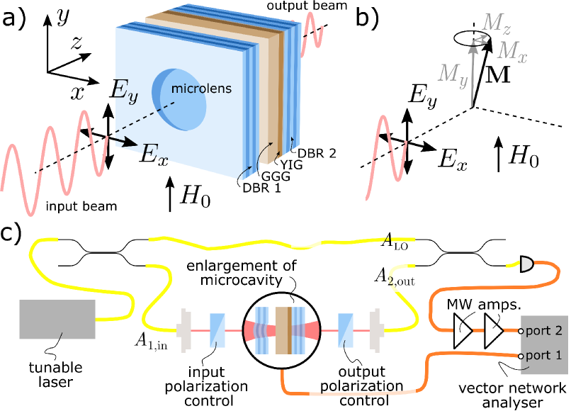
A schematic of the device is shown in Fig. 1(a). Details of the fabrication can be found in Ref. Haigh et al. (2020). It consists of an open micro-cavity Barbour et al. (2011) with an embedded layer of single crystal YIG with growth axis along . The YIG is transferred from a GGG substrate and polymer bonded to a planar dielectric mirror surface. To provide lateral confinement of the optical field, the complementary mirror has an ion-milled micro-lens of radius 90 Dolan et al. (2010). The mirror structure is designed for maximum reflectance at 1300 nm.
The micro-cavity is probed in transmission with a tunable external cavity diode laser, see Fig. 1(a). The orientation of device is shown, with optical axis along . The applied magnetic field and dc-magnetization are along the direction. The magnetization dynamics are driven by a microwave tone from the vector network analyzer (VNA), via an on-chip microwave strip-line antenna aligned along -axis Haigh et al. (2020).
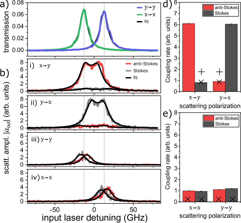
The optical cavity modes have a free spectral range of 6.7 THz and a finesse of 600. A transmission measurements for linearly polarized light along and at around 1317 nm is shown in Fig. 2(a). The modes are linearly polarized, and a Lorentzian fit yields a splitting of 25.7 GHz and linewidths of GHz and GHz.
Next we measure the magnon-scattered optical signal via homodyne detection, using the experimental setup shown in Fig. 1(c). The signal consists of Stokes and anti-Stokes components at optical frequency where is the magnon mode frequency. A local oscillator taken from the input laser is added to the transmitted optical field using a beamsplitter, and mixed on a photodiode. The Stokes and anti-Stokes terms both result in microwave signals at frequency , which interfere. As the laser frequency is swept, the local oscillator phase changes due to the imbalance between the optical path lengths, modulating the interference Neuhaus et al. (1998). The signal oscillates between a minimum and maximum value, from which the amplitude of the Stokes and anti-Stokes components can be extracted . Note that the assignment of the to Stokes or anti-Stokes is not possible from the measurement due to the unknown signs of the signals. However, the assignment can be made based on the laser detuning dependence of the extracted values.
The amplitudes of the measured Stokes and anti-Stokes signals are shown in Fig. 2(b). For cross polarized scattering (i-ii), we see that depending on the input polarization, one of the side-bands is suppressed. For co-polarized scattering (iii-iv), we also observe magnon scattering around the frequency of the correspondingly polarized optical mode. In this case, the measurements are similar to those expected for a standard optomechanical system, with one optical mode. Because we are in the unresolved side-band regime (), the side-band suppression is weak. Remarkably, for cross-polarized scattering the side-band suppression is strong over the entire detuning range. This is despite a mode-splitting similar to the cavity linewidth, and the relaxation of the mode-matching conditions due to the small optical mode volume. Therefore, this suppression cannot be explained by the Faraday effect alone. As shown theoretically in Ref. Liu et al. (2016), side-band suppression in a cavity optomagnonic system can result from the interference of the Faraday interaction and the second order Cotton-Mouton effect. This effect has also been observed in Brillouin light scattering experiments in bulk YIG Wettling et al. (1975). In the following, we show how this arises. Additionally, we find it necessary to include the squeezing of the magnon mode.
The interaction Hamiltonian for the magneto-optical coupling of optical modes and magnon mode has the form
| (1) |
where
| (2) |
The overlap between the three relevant modes is expressed as 111Superscript indicates conjugate only for , with the magnon mode function, and is a material-dependent parameter. For our microcavity, we can set as the optical mode functions Note (2). We can therefore understand the polarization dependent scattering in terms of the elements of , which is defined such that the ac-term of the dielectric constant , where . The separation of the spatial mode overlap and dielectric-tensor-dependent matrix is only possible because of the simple mode structure of the optical cavity, in contrast to, e.g. whispering gallery mode resonators Haigh et al. (2016).
The dielectric tensor can be expanded in powers of magnetization, . Here, the linear in magnetization part is the Faraday term with Levi-Civita symbol . The second order part with four-rank tensor gives rise to the Cotton-Mouton effect (linear birefringence). Due to the strong dc magnetization , the Cotton-Mouton tensor results in an ac-term that contributes to the one-magnon scattering , a dc-term contributing to the static birefringence proportional to , and a two-magnon scattering term Hisatomi et al. (2019). We disregard the latter two parts, as we are interested in only one magnon scattering events, and the birefringence is small compared to the cavity mode splitting. For a cubic material such as YIG, the Cotton-Mouton tensor has only three independent parameters, , , and Nye (1985), and we define to simplify the expressions Prokhorov et al. (1984). The Gaussian modes of our optical microcavity can be treated in paraxial approximation, where only the polarization components of electric-field are considered. This eliminates the -components of the dielectric tensor from our analysis.
Importantly, the effective first-order dielectric tensor contains terms in both and , with different relative phases, leading to interference between the two terms 222See Supplementary information, as can be seen in the structure of
| (3) |
Here, we have used the Cotton-Mouton tensor for YIG with .
Firstly, we see that the diagonal elements of (proportional to those of ) are non-zero, resulting in the co-polarized scattering we observe. Secondly, due to an interference between Faraday and Cotton-Mouton terms the off-diagonal elements of are not equal, resulting in the side-band asymmetry. Although this is the case, the interaction Hamiltonian is still Hermitian, given that . In the case , there is complete side band suppression. Due to the crystal orientation, the Cotton-Mouton effect also results in co-polarized diagonal terms, with .
The output of the cavity at the Stokes (S) and anti-Stokes (AS) frequencies for the different polarization configuration can be calculated from the linearized dynamics using the interaction Hamiltonian and solving the quantum Langevin equations Rameshti et al. (2021). This gives Note (2); Haigh et al. (2016)
| (4) |
where is the input microwave amplitude, and is the detuning of the optical input from the cavity mode frequency , with amplitude , and are the dissipation rates of the optical and magnetic modes, respectively and is the magnon mode frequency. All parameters defining the lineshape are known from the transmission measurements, so linear regression is used to extract the overall amplitude from the data, as shown in Fig. 2(b). Because the efficiency of the microwave coupling is unknown, the ratio of the coupling rates, e.g. , are found. We compare these values to those expected given the elements of the Cotton-Mouton tensor, , and and the Faraday coefficient Stancil and Prabhakar (2009), where the saturation magnetization kAm-1. This analysis, which assumes circular precession of the magnetization, underestimates the cross-polarized side-band suppression, (marked as ) in Fig. 2(d). Note that, neglects the unknown in-plane angle between and the high symmetry crystallographic axis. This adds an angle dependent component to the dielectric tensor with a phase that cannot interfere with the off-diagonal terms Note (2), and therefore cannot increase the sideband suppression from the values above.
To account for the enhanced side-band suppression, we consider the ellipticity of the magnetization precession in a confined magnetic structure. The ellipticity is analogous to squeezing of the amplitudes in quantum optics Sharma et al. (2021), and is introduced via a squeezing parameter Kamra and Belzig (2016). The magnon operators can be diagonalized in a different basis using the Bogoliubov transformation Kamra and Belzig (2016); Sharma et al. (2021). This modifies the coupling rates . Based on the LLG equation in the macrospin approximation, the Kittel mode has ellipicity (using T, T) Sharma et al. (2021). Likewise, the squeezing of the Damon-Eshbach mode on the low energy side of the band is similar to the Kittel mode due to the large in-plane wavevector, resulting in a demagnetizing field dominated by the out-of-plane component Note (2). With this correction, we find , in agreement with experiment, as shown in Fig. 2(d) (diagonal crosses ).
The measured amplitude of the co-polarized signal is a factor of 4 stronger than expected from our calculations, shown as crosses () in Fig. 2(e). We believe this is due to magnetostrictive contributions to the Cotton-Mouton tensor Prokhorov et al. (1984) which are likely to be enhanced in the YIG/GGG membrane by the weak clamping of the polymer bonding.
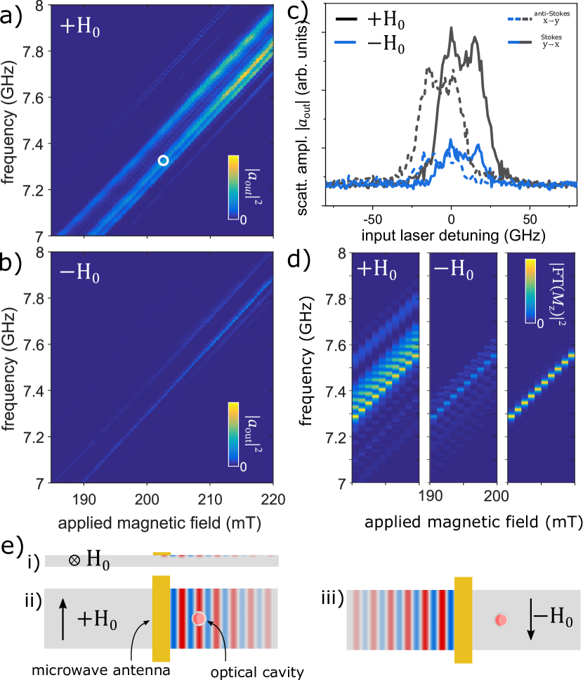
Finally, we identify the magnon modes contributing to the optical scattering in our experiments. The power of the magnon scattered optical signal is shown in Fig. 3, as a function of applied positive (a) and negative (b) magnetic field and microwave drive frequency. The signal strongly depends on the sign of the magnetic field. The lineshape as a function input optical if frequency is unaffected (Fig. 3(c), hinting that this effect is not related to the optomagnonic coupling. Instead, we consider the schematic of the microwave antenna shown in Fig. 3(e). The magnetic field is applied along the length of waveguide, such that magnons with wavevector perpendicular to the magnetic field are excited. These are the Damon-Eshbach modes Eshbach and Damon (1960), which are chiral surface modes propagating in one direction on each surface. As the microwave field from the antenna decays rapidly with distance, it only couples to the mode on the top surface. For one sign of the magnetic field, the propagation of the driven mode is towards the optical cavity, whereas for the opposite magnetic field the propagation is away. This is non-reciprocal in the sense that, for one field direction, while the microwave-generated magnons propagate towards the optical cavity and participate in the optical scattering, the magnons generated by optical scattering processes are driven away from the microwave coupling line.
We use micromagnetic modeling to confirm that the Damon-Eshbach modes are observed in experiments Donahue (1999). The model is based on the approximate geometry of the ferromagnetic layer, and simulates the ring-down of the magnetization dynamics following an impulsive field with spatial distribution calculated from the Biot-Savart law based on current uniformly distributed in the microwave antenna Note (2). The frequency response is calculated from the Fourier transform of the ring-down. This is repeated for the different values of applied magnetic field. The optical scattering response is calculated by averaging the magnetization over the optical mode volume (Fig. 3(d) left two panels).The location of Kittel mode is found by averaging over the entire magnetic volume, resulting in the bright mode in Fig. 3(d) right panel. We note that the micromagnetic modeling does not include the magneto-crystalline anisotropy, leading to a frequency offset in comparison to the measured data. However, the broad features are in agreement with the experiment, as shown in Fig. 3(a-b). This includes the asymmetry in the response for positive/negative magnetic fields and the broad band of spin waves above the Kittel mode, with a dark band corresponding to the wavevectors not compatible with the microwave antenna.
In conclusion, we have measured the polarization dependent magnon-scattering in magneto-optical micro-cavities. A co-polarized process involving one optical mode is observed. This process is stronger than expected from the Cotton-Mouton effect, and has a similar phenomenology to an optomechanical system in the non-resolved sideband regime (cavity linewidth of 12 GHz greater than the magnon frequency of 8 GHz), where the side-band suppression is weak. However, for cross-polarized scattering a strong broadband side-band suppression is observed. Interference between the first-order Faraday effect, and an effective first-order Cotton-Mouton magneto-optical effects gives rise to an intrinsic asymmetry between Stokes and anti-Stokes processes. This asymmetry is further enhanced by the intrinsic ground state squeezing naturally existing in anisotropic magnetic structures Kamra and Belzig (2016); Sharma et al. (2021).
The cross-polarized scattering is reminiscent of the recently explored coherent scattering approach to levitated optomechanical systems Delić et al. (2019). There, efficient mechanical cooling was achieved by alleviating the laser phase noise heating. The cross-polarization scattering in magneto-optical cooling Sharma et al. (2018); Bittencourt et al. (2019) could also benefit from similar insensitivity to laser phase noise heating. Our experiments also show that the microwave antenna couples to directed Damon-Eshbach surface modes, hinting at the non-reciprocal functionality possible because of time-reversal symmetry breaking of the ferromagnetic magnetization Jalas et al. (2013).
Acknowledgements
This work was supported by the European Union’s Horizon 2020 Research and Innovation Programme under Grant Agreement No. 732894 (FET Proactive HOT). We are grateful for advice on micro-magnetic modeling from Pierre Roy.
References
- Osada et al. (2016) A. Osada, R. Hisatomi, A. Noguchi, Y. Tabuchi, R. Yamazaki, K. Usami, M. Sadgrove, R. Yalla, M. Nomura, and Y. Nakamura, “Cavity Optomagnonics with Spin-Orbit Coupled Photons,” Phys. Rev. Lett. 116, 223601 (2016).
- Zhang et al. (2016) Xufeng Zhang, Na Zhu, Chang-Ling Zou, and Hong X. Tang, “Optomagnonic Whispering Gallery Microresonators,” Phys. Rev. Lett. 117, 123605 (2016).
- Haigh et al. (2016) J. A. Haigh, A. Nunnenkamp, A. J. Ramsay, and A. J. Ferguson, “Triple-Resonant Brillouin Light Scattering in Magneto-Optical Cavities,” Phys. Rev. Lett. 117, 133602 (2016).
- Hisatomi et al. (2016) R. Hisatomi, A. Osada, Y. Tabuchi, T. Ishikawa, A. Noguchi, R. Yamazaki, K. Usami, and Y. Nakamura, “Bidirectional conversion between microwave and light via ferromagnetic magnons,” Phys. Rev. B 93, 174427 (2016).
- Lambert et al. (2020) Nicholas J. Lambert, Alfredo Rueda, Florian Sedlmeir, and Harald G. L. Schwefel, “Coherent Conversion Between Microwave and Optical Photons—An Overview of Physical Implementations,” Adv. Quantum Technol. 3, 1900077 (2020).
- Zhu et al. (2021) Na Zhu, Xufeng Zhang, Xu Han, Chang-Ling Zou, and Hong X. Tang, “Inverse Faraday Effect in an Optomagnonic Waveguide,” (2021), arXiv:2012.11119 .
- Huebl et al. (2013) Hans Huebl, Christoph W. Zollitsch, Johannes Lotze, Fredrik Hocke, Moritz Greifenstein, Achim Marx, Rudolf Gross, and Sebastian TB Goennenwein, “High cooperativity in coupled microwave resonator ferrimagnetic insulator hybrids,” Phys. Rev. Lett. 111, 127003 (2013).
- Zhang et al. (2014) X. Zhang, C. L. Zou, L. Jiang, and H. X. Tang, “Strongly Coupled Magnons and Cavity Microwave Photons,” Phys. Rev. Lett. 113, 156401 (2014).
- Tabuchi et al. (2014) Yutaka Tabuchi, Seiichiro Ishino, Toyofumi Ishikawa, Rekishu Yamazaki, Koji Usami, and Yasunobu Nakamura, “Hybridizing Ferromagnetic Magnons and Microwave Photons in the Quantum Limit,” Phys. Rev. Lett. 113, 083603 (2014).
- Zhu et al. (2020) Na Zhu, Xufeng Zhang, Xufeng Zhang, Xu Han, Xu Han, Chang-Ling Zou, Chang-Ling Zou, Changchun Zhong, Changchun Zhong, Chiao-Hsuan Wang, Chiao-Hsuan Wang, Liang Jiang, Liang Jiang, and Hong X. Tang, “Waveguide cavity optomagnonics for microwave-to-optics conversion,” Optica 7, 1291 (2020).
- Haigh et al. (2020) J.A. Haigh, R.A. Chakalov, and A.J. Ramsay, “Subpicoliter Magnetoptical Cavities,” Phys. Rev. Applied 14, 044005 (2020).
- Rameshti et al. (2021) Babak Zare Rameshti, Silvia Viola Kusminskiy, James A. Haigh, Koji Usami, Dany Lachance-Quirion, Yasunobu Nakamura, Can-Ming Hu, Hong X. Tang, Gerrit E. W. Bauer, and Yaroslav M. Blanter, “Cavity Magnonics,” (2021), arXiv:2106.09312 .
- Aspelmeyer et al. (2014) Markus Aspelmeyer, Tobias J. Kippenberg, and Florian Marquardt, “Cavity optomechanics,” Rev. Mod. Phys. 86, 1391 (2014).
- Viola Kusminskiy et al. (2016) Silvia Viola Kusminskiy, Hong X. Tang, and Florian Marquardt, “Coupled spin-light dynamics in cavity optomagnonics,” Phys. Rev. A 94, 033821 (2016).
- Sharma et al. (2018) Sanchar Sharma, Yaroslav M. Blanter, and Gerrit E. W. Bauer, “Optical Cooling of Magnons,” Phys. Rev. Lett. 121, 087205 (2018).
- Bittencourt et al. (2019) Victor A. S. V. Bittencourt, Verena Feulner, and Silvia Viola Kusminskiy, “Magnon heralding in cavity optomagnonics,” Phys. Rev. A 100, 013810 (2019).
- Šimić et al. (2020) Fran Šimić, Sanchar Sharma, Yaroslav M. Blanter, and Gerrit E. W. Bauer, “Coherent pumping of high-momentum magnons by light,” Phys. Rev. B 101, 100401(R) (2020).
- Sharma et al. (2017) Sanchar Sharma, Yaroslav M. Blanter, and Gerrit E. W. Bauer, “Light scattering by magnons in whispering gallery mode cavities,” Phys. Rev. B 96, 094412 (2017).
- Liu et al. (2016) Tianyu Liu, Xufeng Zhang, Hong X. Tang, and Michael E. Flatté, “Optomagnonics in magnetic solids,” Phys. Rev. B 94, 060405 (2016).
- Graf et al. (2020) Jasmin Graf, Sanchar Sharma, Hans Huebl, and Silvia Viola Kusminskiy, “Design of an optomagnonic crystal: Towards optimal magnon-photon mode matching at the microscale,” (2020), arXiv:2012.00760 .
- Barbour et al. (2011) Russell J. Barbour, Paul A. Dalgarno, Arran Curran, Kris M. Nowak, Howard J. Baker, Denis R. Hall, Nick G. Stoltz, Pierre M. Petroff, and Richard J. Warburton, “A tunable microcavity,” Journal of Applied Physics 110, 053107 (2011).
- Dolan et al. (2010) Philip R. Dolan, Gareth M. Hughes, Fabio Grazioso, Brian R. Patton, and Jason M. Smith, “Femtoliter tunable optical cavity arrays,” Opt. Lett. 35, 3556 (2010).
- Neuhaus et al. (1998) Rudolf Neuhaus, Matthew J. Sellars, Stephen J. Bingham, and Dieter Suter, “Breaking the Stokes–anti-Stokes symmetry in Raman heterodyne detection of magnetic-resonance transitions,” Phys. Rev. A 58, 4961 (1998).
- Wettling et al. (1975) W. Wettling, M. G. Cottam, and J. R. Sandercock, “The relation between one-magnon light scattering and the complex magneto-optic effects in YIG,” J. Phys. C: Solid State Phys. 8, 211 (1975).
- Note (1) Superscript indicates conjugate only for .
- Note (2) See Supplementary information.
- Hisatomi et al. (2019) R. Hisatomi, A. Noguchi, R. Yamazaki, Y. Nakata, A. Gloppe, Y. Nakamura, and K. Usami, “Helicity-Changing Brillouin Light Scattering by Magnons in a Ferromagnetic Crystal,” Phys. Rev. Lett. 123, 207401 (2019).
- Nye (1985) J. F. Nye, Physical Properties of Crystals: Their Representation by Tensors and Matrices (Oxford University Press, Oxford, New York, 1985).
- Prokhorov et al. (1984) A. M. Prokhorov, G. A. Smolenskiĭ, and A. N. Ageev, “Optical phenomena in thin-film magnetic waveguides and their technical application,” Sov. Phys. Usp. 27, 339 (1984).
- Stancil and Prabhakar (2009) Daniel D. Stancil and Anil Prabhakar, Spin Waves: Theory and Applications (Springer US, 2009).
- Sharma et al. (2021) Sanchar Sharma, Victor A. S. V. Bittencourt, Alexy D. Karenowska, and Silvia Viola Kusminskiy, “Spin cat states in ferromagnetic insulators,” Phys. Rev. B 103, L100403 (2021).
- Kamra and Belzig (2016) Akashdeep Kamra and Wolfgang Belzig, “Super-Poissonian Shot Noise of Squeezed-Magnon Mediated Spin Transport,” Phys. Rev. Lett. 116, 146601 (2016).
- Eshbach and Damon (1960) J. R. Eshbach and R. W. Damon, “Surface Magnetostatic Modes and Surface Spin Waves,” Phys. Rev. 118, 1208 (1960).
- Donahue (1999) Michael J. Donahue, “OOMMF User’s Guide, Version 1.0,” (1999).
- Delić et al. (2019) Uroš Delić, Manuel Reisenbauer, David Grass, Nikolai Kiesel, Vladan Vuletić, and Markus Aspelmeyer, “Cavity Cooling of a Levitated Nanosphere by Coherent Scattering,” Phys. Rev. Lett. 122, 123602 (2019).
- Jalas et al. (2013) Dirk Jalas, Alexander Petrov, Manfred Eich, Wolfgang Freude, Shanhui Fan, Zongfu Yu, Roel Baets, Miloš Popović, Andrea Melloni, John D. Joannopoulos, Mathias Vanwolleghem, Christopher R. Doerr, and Hagen Renner, “What is — and what is not — an optical isolator,” Nat. Photonics 7, 579 (2013).