Propagation-invariant vortex Airy beam whose singular point follows its main lobe
Abstract
We propose and demonstrate a novel vortex Airy beam which is a superposition of an Airy beam and its laterally sheared beam with a phase shift. This new-type of vortex Airy beam exhibits stable propagation dynamics, wherein its singular point closely follows its main lobe, unlike conventional vortex Airy beams. Notably, the orbital angular mode purity of this new vortex Airy beam is up to 10 % better than that of a conventional vortex Airy beam. We anticipate that this new type of vortex Airy beam, which combines the characteristics of an optical vortex and a diffraction-free Airy beam, will facilitate new directions in applications such as microscopy, material processing and nonlinear optics.
-
June 2021
Keywords: Optical Vortex, Orbital Angular Momentum, Airy beams
1 Introduction
An Airy beam is a class of diffraction-free beams which include Bessel and Mathieu beams [1]. The first theoretical investigation of such beams was reported in 1979. Berry and Balazs showed that a 1D-Airy wave packet is a solution to the potential-free Schrödinger equation [2], following this, Besieris et. al. also suggested a 2D-Airy wave packet as a solution in 1994 [3]. After many years, in 2007, the first finite-energy Airy beam was experimentally demonstrated by Siviloglou et. al. [4]. Having unique features like propagation-invariance and a self-accelerating parabolic trajectory [1, 5], the Airy beam has been utilized in applications including selective plane illumination microscopy (SPIM) [6, 7, 8, 9], rapid three-dimensional volumetric imaging [10], optical coherence tomography [11], material processing [12, 13], and optical micromanipulation [14].
Soon after the experimental demonstration of an Airy beam, a vortex Airy beam was investigated [15]. Conventional vortex Airy beams have a characteristic wherein the optical vortex imposed on the main lobe of the beam easily deforms spatially as the Airy beam propagates away from its focal point. This is because the singular point of the main vortex lobe (the main singular point) deviates from the parabolic trajectory of the vortex Airy beam [16, 17]. It is difficult to make the singular point follow the parabolic course of the Airy beam and as such, this has been seen as a barrier to their use in practical applications. One such promising application is stimulated emission depletion selective plane illumination microscopy (STED-SPIM) [18, 19, 20], which uses the combination of an Airy beam for the excitation beam and a vortex Airy beam for the STED beam. This next-generation of STED microscopy would yield fast and high-resolution imaging with an unparalleled field of view.
In this manuscript, we propose a new vortex Airy beam, whose singular point follows its main lobe. This new vortex Airy beam is composed of two conventional Airy beams which are the laterally- and phase-shifted with respect to one another. Herein, we refer to this as the new-type vortex Airy beam. We present our research as follows; first, we introduce the basic concept of the new-type vortex Airy beam, following which we theoretically examine the propagation dynamics and the orbital angular momentum (OAM) distribution of the beam. We then detail our experimental generation of the new-type vortex Airy beam, and investigate its propagation dynamics. This is followed by discussion and conclusions of our work.
2 Theoretical description of vortex Airy beams
2.1 Basic concept
In order to introduce a new-type vortex Airy beam, we start by examining the paraxial equation of diffraction,
| (1) |
where is a normalized axis, is a scaling factor of the transverse plane, is a scaling factor of the propagation axis, is the wavenumber with the wavelength and the refractive index . The electric field envelope of a 2D-Airy beam is a solution to Eq. (1) [4, 21]:
| (2) | |||||
where (,) gives the lateral constant shift of the Airy beam, represents the Airy function, and is an exponential truncation factor.
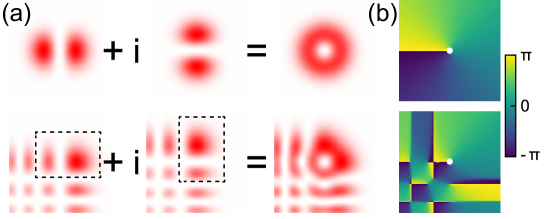
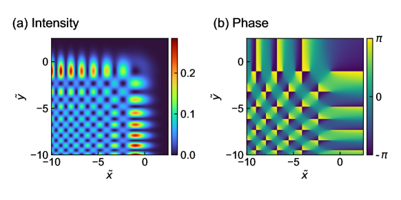
The proposed Airy vortex beam is composed of two conventional Airy beams which are superimposed with one another. As shown in Fig. 1(a), the Laguerre–Gaussian mode with the radial index and the azimuthal index (LG01 mode) can be expressed as the superposition of Hermite–Gaussian modes of order and (HG10 and HG01) with the phase shift of [22]. Now, we can regard parts of an Airy beam as a higher order Hermite–Gaussian mode. For example, the part of an Airy beam which comprises the main lobe and its left neighbor lobe can be approximated as the Hermite–Gaussian mode of order . Thus, the superposition of two Airy beams which have a relative phase of and a lateral shift, is expected to be a vortex Airy beam carrying OAM. In fact, there will be an azimuthal phase shift of around the main singular point (the singular point of the main vortex lobe). In this manuscript, we call this beam a new-type vortex Airy beam with OAM (Fig. 1(b)). Similarly, the new-type vortex Airy beam with OAM can be generated via the superposition of two Airy beams with both a lateral shift and a -phase shift.
We here express a new-type vortex Airy beam with OAM as
| (3) |
where and , respectively, represent the th real zeros of and ( and ) [23]. The total power of the new-type vortex Airy beam in the beam cross section is derived from Parseval’s theorem as
| (4) |
An new-type vortex Airy beam, while being a non-real solution to the paraxial equation owing to its infinite power, is truly propagation-invariant. We consider this beam to be a perfect vortex Airy beam. As expected, when , the new-type vortex Airy beam has a finite energy distribution.
New-type vortex Airy beams with higher-order OAM can be obtained through the superposition of more than two Airy beams. For example, a new-type vortex Airy beam with OAM is expressed as follows:
| (5) | |||||
2.2 Propagation dynamics of the main singular point
We show that the new-type vortex Airy beam has a vortex lobe which remains stationary (i.e. the position of the singular point does not change) as the distance from the focus () changes. This is in contrast to a conventional vortex Airy beam; the characteristic of which is shown in Fig. 2(a). The deformation of the intensity distribution of the conventional vortex Airy beam is attributed to the main singular point leaving the parabolic trajectory with respect to propagation distance. In the case of the perfect new-type vortex Airy beam (with ) the main singular point does follow a parabolic trajectory; this can be seen through solution of Eq. (3) as follows:
| (6) |
Moreover, the perfect new-type vortex Airy beam maintains the same intensity distribution for any propagation distance; this is shown in Fig. 2(b).

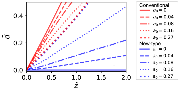
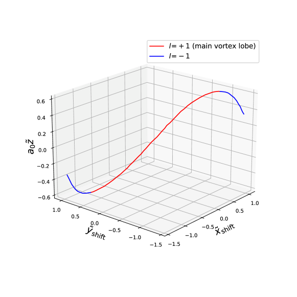
While the intensity distribution of the perfect new-type vortex Airy beam can be theoretically modeled, it is a non-real solution to the paraxial equation. Real solutions with have also been investigated in this work. In such cases, we observe that there is some deviation of the main singular point from the parabolic trajectory, as the beam propagates away from focus. The amount of deviation (as described in Appendix B) is however smaller than that observed in a conventional vortex Airy beam in cases where . Plots of deviation as a function of axial position () for different values of are shown in Fig. 3.
When , the amplitude envelope of the new-type vortex Airy beam decays to times in the main vortex lobe since . Usually, the exponential truncation factor is experimentally made small (). The smaller is, the smaller the amount of deviation is at the same propagation distance for the new-type vortex Airy beams, in comparison with conventional vortex Airy beams. If we consider the case where , the decay of the new-type vortex Airy beam is in its 26th side lobe since . Here, the new-type vortex Airy beam preserves the ring shape of the main vortex lobe (as shown in Fig. 2(d)) as it propagates, whereas the main vortex lobe of the conventional vortex Airy beam separates as it propagates (as shown in Fig. 2(c)). We find that for values , the ring shape of the main vortex lobe is well-preserved upon propagation and the singular point follows the parabolic trajectory. This is detailed in Appendix B.
2.3 Orbital angular momentum spectrum
As vortex Airy beams are not symmetric around the main singular point, they carry not only OAM, but also the other OAM across their profile. Here we examine the OAM spectrum of these vortex Airy beams. The OAM spectrum of the electric field envelope at is defined by
| (7) |
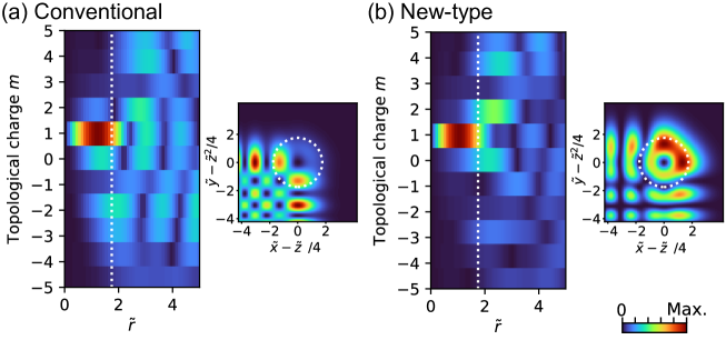
where represents the topological charge (or OAM in a reduced Planck constant ), and are the normalized radius and the azimuthal angle of the polar coordinates in the transverse plane respectively [24]. Figure 4 shows the absolute amplitude distributions of of the OAM spectra of the perfect conventional vortex Airy beam with OAM and the perfect new-type Airy vortex beam with OAM. In the inner part of the main vortex lobe (), both of the beams mainly contain optical vortex modes. Figure 5 shows a plot of the OAM spectrum of the inner part of the main vortex lobe of both conventional and new-type vortex Airy beams, where the Intensity () is derived as . The mode purity of the perfect new-type vortex Airy beam is , while that of the perfect conventional Airy vortex beam is . Thus, the new-type vortex Airy beam is superior in terms of OAM mode purity as well as beam propagation characteristics.

3 Experimental Results and Discussions
3.1 Experimental setup
We experimentally investigated the propagation dynamics of new-type vortex Airy beams, generated from an in-house-built Ti:sapphire regenerative amplifier pulsed laser system. The output from this laser was horizontally polarized and had a Gaussian spatial profile with a beam radius of 3 mm. Spectral purity was maintained by passing the beam through a bandpass filter (central wavelength, 800 nm; bandwidth, 5 nm). The laser beam was then incident on a spatial light modulator (SLM) which acted as a phase mask. The details of the phase mask displayed on the SLM can be found in Appendix C. The spatially phase-modulated laser beam was then transformed into a new-type vortex Airy beam by a converging lens ( mm). Using a CMOS imaging sensor in conjunction with a mechanical stage, we recorded the profiles of the generated vortex Airy beams at different propagation distances, in the vicinity of the focus. For comparison purposes, we generated a conventional vortex Airy beam by implementing a phase mask with a sum of a cubic and a spiral phase distribution on the SLM [25].
3.2 Results and Discussion
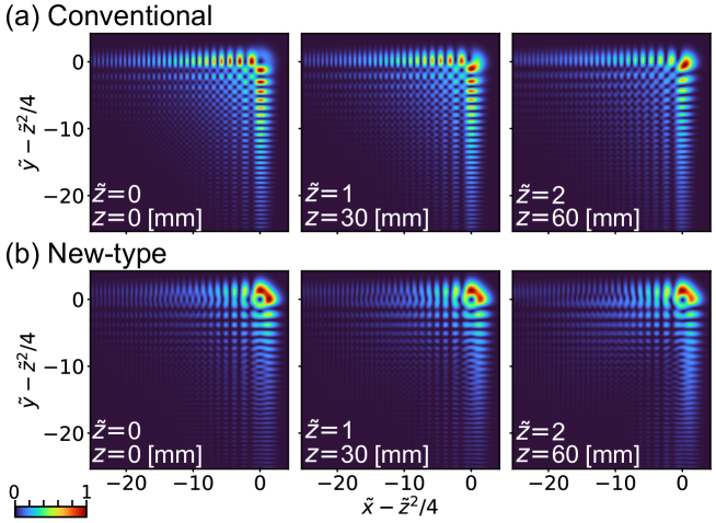
Figure 6 shows the experimental propagation dynamics of a finite-energy new-type vortex Airy beam with OAM and a finite-energy conventional vortex Airy beam with OAM. The factors of the transverse plane, the propagation axis and the exponential truncation were evaluated to be mm, mm and , respectively. The propagation dynamics of the conventional vortex Airy beam (Fig. 6(a)) and the new-type vortex Airy beam (Fig. 6(b)) clearly agree well with the numerical simulations shown in Figs. 2(c) and 2(d), respectively. The main vortex lobe of the finite-energy conventional vortex Airy beam deformed at and finally divided into two spots at , which as mentioned is attributed to the main singular point deviating from the parabolic trajectory. In contrast, the main vortex lobe of the new-type vortex Airy beam maintained its ring shape even at . This is consistent the main singular point of this new-type vortex Airy beam following the parabolic trajectory (as expected, given was small).
In order to show that a new-type vortex Airy beam has an singular point in the main vortex lobe, we implemented an interference measurement at with a reference beam (Fig. 7). This was done using the random mask encoding method [15] wherein both object and reference beams were simultaneously generated from the same phase mask. The interference image had a two-pronged fork pattern in the main vortex lobe (Fig. 7(a)) and this was consistent with that predicted via numerical simulation (Fig. 7(b)). Thus, the dominant topological charge of the main vortex lobe was +1 [26, 27, 28], which was consistent with the OAM spectrum shown in Fig. 5. These results indicate that these new-type vortex Airy beams comprise a new family of vortex Airy beams.

We comment on future applications of the new-type vortex Airy beams. The dark spot of the singular point is well-preserved in the region of , although the shape of the main vortex lobe is not perfectly symmetric especially on propagation. The new-type vortex Airy beams are expected to possess the self-healing properties since they are indeed composed of Airy beams, while it is needed to examine of their self-healing properties in future work. Thus, they can be useful for the STED beam in STED-SPIM. Light-sheet imaging [6, 7, 8, 9], material processing [29, 30, 31] and nonlinear optics [32] may be another fruitful direction.
4 Conclusion
In conclusion, we have presented theoretical and experimental investigations into the generation of a new-type vortex Airy beam. These beams exhibit very stable propagation dynamics compared to conventional vortex Airy beams, wherein the position of the singular point within the beam intensity profile does not vary significantly on propagation from focus. This is in contrast to conventional vortex Airy beams which exhibit significant movement of the singular point with beam propagation. We anticipate that the propagation-insensitivity of the singular point in these new-type vortex Airy beams may herald new innovations in applications such as STED microscopy, light-sheet imaging, material processing and nonlinear optics.
Appendix A Conventional vortex Airy beam
In this section, we derive a formula which describes a conventional vortex Airy beam that introduced in Ref. [15]. The electric field envelope of the Airy beam
| (8) | |||||
satisfies the normalized paraxial equation of monochromatic electromagnetic waves with wavenumber
| (9) |
where is a normalized axis in the beam cross section, is a scale factor of the transverse plane, is a normalized propagation axis, defines the lateral shift of the Airy beam, and is a truncation factor.
When an orbital angular momentum operator [33] commutes with the operators , , and on both sides of Eq. (9), we get
| (10) |
thus is also a solution of Eq. (9). The explicit form of is given by
| (11) | |||||
| (12) | |||||
where is a vortex array imposed on an Airy beam (Fig. 8). The emergence of a vortex array was reported in the first study of vortex Airy beams [15]. In general, the orbital angular momentum operator adds an orbital angular momentum . For example, when the orbital angular momentum operator acts on a Laguerre–Gaussian mode with the radial index and azimuthal index (LGpℓ mode), the mode will be converted into the LGp(ℓ±1) mode [33]. (Eq. (11)), however, has the terms of an Airy beam as well as that of a vortex array Airy beam, the characteristic of which causes a degradation of the beam profile with distance from its focus ().
Here we show a beam described by Eq. (11) which is generated by the spatial Fourier transformation of an LG01 mode modulated by a cubic phase. The inverse spatial Fourier transform of the Airy beam at is defined as
where () is a normalized wavenumber in the transverse plane [15]. When , we get
| (14) |
The spatial Fourier transform of Eq. (14) is
| (15) |
which physically means that a Gaussian beam whose beam radius is with a cubic phase , propagating through a Fourier lens, generates a finite energy Airy beam at its focus. From Eq. (15), a beam described by is obtained by Fourier lens transformation of LG01 mode beam with a cubic phase,
| (16) |
A conventional vortex Airy beam is usually generated by applying the sum of a cubic phase and a spiral phase to a Gaussian beam [15, 16, 25]. We assume that the radius of the Gaussian beam is . When , % of the phase modulated Gaussian beam is the phase modulated LG01 mode beam in terms of energy ratio. Most parts of the conventional vortex Airy beam is described by Eq. (11). Thereby, obtaining the simple expression of conventional vortex Airy beam, we regard as .
Appendix B Propagation dynamics of the main vortex lobe of the new-type vortex Airy beam
The position of the singular point of the main vortex lobe of a finite energy new-type beam shifts from the parabolic trajectory . The shift can be numerically fitted by hyperbolic tangent functions.
| (23) | |||||
| (26) | |||||
| (31) |
and singular points appear at . The former one is the singular point of the main vortex lobe. This singular point collides with another singular point, following which these points vanish at (Fig. 9).
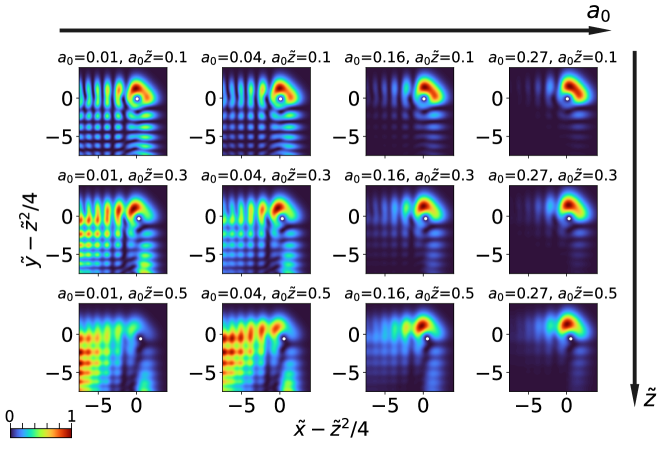
The main vortex lobe of a finite energy new-type vortex Airy beam deforms with propagation distance. Figure. 10 depicts propagation dynamics of various new-type vortex Airy beams at and . The shape of the vortex lobe resembles a closed ring at , and it becomes progressively more open as the value of increases, as seen for and . This characteristics is due to the deviation of the main singular point from the parabolic trajectory (), which is significant with respect to the size of the vortex main lobe.
Appendix C Phase mask for new-type vortex Airy beam
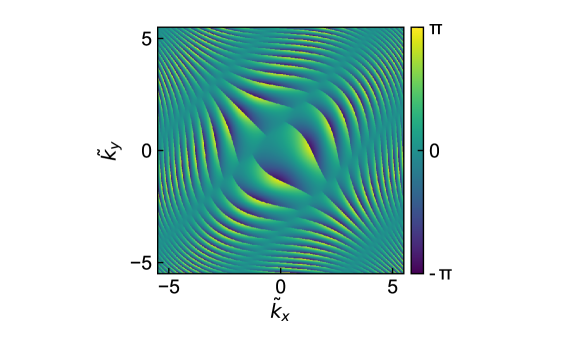
Here we detail the characteristics of the phase mask used to tailor a new-type vortex Airy beam. The Fourier transform of a new-type vortex Airy beam is described by the following expression
| (32) |
where and represent the th real zeros of and ( and ) respectively [23]. We assume the input beam is a Gaussian beam with beam radius in the plane. Since we need both phase modulation and amplitude modulation through a phase mask, we calculated the phase mask pattern by using the Davis’s method [34, 35, 36]. Figure 11 shows the phase distribution that we displayed on the SLM. When , the radius of the Gaussian beam is in the plane or in the plane. In experiments, the beam radius in the plane is usually a constant value, so is determined by the scale factor .
References
References
- [1] Efremidis N K, Chen Z, Segev M and Christodoulides D N 2019 Optica 6 686–701 URL http://www.osapublishing.org/optica/abstract.cfm?URI=optica-6-5-686
- [2] Berry M V and Balazs N L 1979 American Journal of Physics 47 264–267 (Preprint https://doi.org/10.1119/1.11855) URL https://doi.org/10.1119/1.11855
- [3] Besieris I M, Shaarawi A M and Ziolkowski R W 1994 American Journal of Physics 62 519–521 (Preprint https://doi.org/10.1119/1.17510) URL https://doi.org/10.1119/1.17510
- [4] Siviloglou G A, Broky J, Dogariu A and Christodoulides D N 2007 Phys. Rev. Lett. 99(21) 213901 URL https://link.aps.org/doi/10.1103/PhysRevLett.99.213901
- [5] Dholakia K 2008 Nature 451 413 URL https://doi.org/10.1038/451413a
- [6] Vettenburg T, Dalgarno H I C, Nylk J, Coll-Lladó C, Ferrier D E K, Čižmár T, Gunn-Moore F J and Dholakia K 2014 Nature Methods 11 541–544 URL https://doi.org/10.1038/nmeth.2922
- [7] Yang Z, Prokopas M, Nylk J, Coll-Lladó C, Gunn-Moore F J, Ferrier D E K, Vettenburg T and Dholakia K 2014 Biomed. Opt. Express 5 3434–3442 URL http://www.osapublishing.org/boe/abstract.cfm?URI=boe-5-10-3434
- [8] Nylk J, McCluskey K, Preciado M A, Mazilu M, Yang Z, Gunn-Moore F J, Aggarwal S, Tello J A, Ferrier D E K and Dholakia K 2018 Science Advances 4 (Preprint https://advances.sciencemag.org/content/4/4/eaar4817.full.pdf) URL https://advances.sciencemag.org/content/4/4/eaar4817
- [9] Corsetti S, Wijesinghe P, Poulton P B, Sakata S, Vyas K, Herrington C S, Nylk J, Gasparoli F and Dholakia K 2020 OSA Continuum 3 1068–1083 URL http://www.osapublishing.org/osac/abstract.cfm?URI=osac-3-4-1068
- [10] Kozawa Y and Sato S 2019 Scientific Reports 9 11687 ISSN 2045-2322 URL https://doi.org/10.1038/s41598-019-48265-3
- [11] Zhang M, Ren Z and Yu P 2019 Opt. Lett. 44 3158–3161 URL http://ol.osa.org/abstract.cfm?URI=ol-44-12-3158
- [12] Mathis A, Courvoisier F, Froehly L, Furfaro L, Jacquot M, Lacourt P A and Dudley J M 2012 Applied Physics Letters 101 071110 (Preprint https://doi.org/10.1063/1.4745925) URL https://doi.org/10.1063/1.4745925
- [13] Gecevičius M, Beresna M, Drevinskas R and Kazansky P G 2014 Opt. Lett. 39 6791–6794 URL http://ol.osa.org/abstract.cfm?URI=ol-39-24-6791
- [14] Baumgartl J, Mazilu M and Dholakia K 2008 Nature Photonics 2 675–678 URL https://doi.org/10.1038/nphoton.2008.201
- [15] Mazilu M, Baumgartl J, Čižmár T and Dholakia K 2009 Accelerating vortices in Airy beams Laser Beam Shaping X vol 7430 ed Forbes A and Lizotte T E International Society for Optics and Photonics (SPIE) pp 68 – 75 URL https://doi.org/10.1117/12.826372
- [16] Dai H T, Liu Y J, Luo D and Sun X W 2010 Opt. Lett. 35 4075–4077 URL http://ol.osa.org/abstract.cfm?URI=ol-35-23-4075
- [17] Dai H T, Liu Y J, Luo D and Sun X W 2011 Opt. Lett. 36 1617–1619 URL http://ol.osa.org/abstract.cfm?URI=ol-36-9-1617
- [18] Friedrich M, Gan Q, Ermolayev V and Harms G 2011 Biophysical Journal 100 L43–L45 ISSN 0006-3495 URL https://www.sciencedirect.com/science/article/pii/S0006349511003031
- [19] Scheul T, Wang I and Vial J C 2014 Opt. Express 22 30852–30864 URL http://www.opticsexpress.org/abstract.cfm?URI=oe-22-25-30852
- [20] Hernández J M, Buisson A, Wang I and Vial J C 2020 Biomed. Opt. Express 11 660–671 URL http://www.osapublishing.org/boe/abstract.cfm?URI=boe-11-2-660
- [21] Siviloglou G A and Christodoulides D N 2007 Opt. Lett. 32 979–981 URL http://ol.osa.org/abstract.cfm?URI=ol-32-8-979
- [22] Allen L, Beijersbergen M W, Spreeuw R J C and Woerdman J P 1992 Phys. Rev. A 45(11) 8185–8189 URL https://link.aps.org/doi/10.1103/PhysRevA.45.8185
- [23] NIST Digital Library of Mathematical Functions http://dlmf.nist.gov/, Release 1.1.0 of 2020-12-15 F. W. J. Olver, A. B. Olde Daalhuis, D. W. Lozier, B. I. Schneider, R. F. Boisvert, C. W. Clark, B. R. Miller, B. V. Saunders, H. S. Cohl, and M. A. McClain, eds. URL http://dlmf.nist.gov/
- [24] Yamane K, Yang Z, Toda Y and Morita R 2014 New Journal of Physics 16 053020 URL https://doi.org/10.1088/1367-2630/16/5/053020
- [25] Li H, Liu H and Chen X 2018 Opt. Express 26 21204–21209 URL http://www.opticsexpress.org/abstract.cfm?URI=oe-26-16-21204
- [26] Baranova N, Zel’Dovich B Y, Mamaev A, Pilipetskii N and Shkukov V 1981 JETP Lett 33 206
- [27] Heckenberg N R, McDuff R, Smith C P and White A G 1992 Opt. Lett. 17 221–223 URL http://ol.osa.org/abstract.cfm?URI=ol-17-3-221
- [28] Suzuki M, Yamane K, Sakamoto M, Oka K, Toda Y and Morita R 2018 Opt. Express 26 2584–2598 URL http://www.opticsexpress.org/abstract.cfm?URI=oe-26-3-2584
- [29] Toyoda K, Miyamoto K, Aoki N, Morita R and Omatsu T 2012 Nano letters 12 3645–3649 URL http://pubs.acs.org/doi/abs/10.1021/nl301347j
- [30] Toyoda K, Takahashi F, Takizawa S, Tokizane Y, Miyamoto K, Morita R and Omatsu T 2013 Phys. Rev. Lett. 110(14) 143603 URL https://link.aps.org/doi/10.1103/PhysRevLett.110.143603
- [31] Nakamura R, Kawaguchi H, Iwata M, Kaneko A, Nagura R, Kawano S, Toyoda K, Miyamoto K and Omatsu T 2019 Opt. Express 27 38019–38027 URL http://www.opticsexpress.org/abstract.cfm?URI=oe-27-26-38019
- [32] Ellenbogen T, Voloch-Bloch N, Ganany-Padowicz A and Arie A 2009 Nature photonics 3 395–398 URL https://doi.org/10.1038/nphoton.2009.95
- [33] Volyar A V and Fadeeva T A 2006 Optics and Spectroscopy 101 450–457 URL https://doi.org/10.1134/S0030400X06090190
- [34] Davis J A, Cottrell D M, Campos J, Yzuel M J and Moreno I 1999 Appl. Opt. 38 5004–5013 URL http://ao.osa.org/abstract.cfm?URI=ao-38-23-5004
- [35] Arrizón V, Ruiz U, Carrada R and González L A 2007 J. Opt. Soc. Am. A 24 3500–3507 URL http://josaa.osa.org/abstract.cfm?URI=josaa-24-11-3500
- [36] Ando T, Ohtake Y, Matsumoto N, Inoue T and Fukuchi N 2009 Opt. Lett. 34 34–36 URL http://ol.osa.org/abstract.cfm?URI=ol-34-1-34