Ultrasonic chaining of emulsion droplets
Abstract
Emulsion droplets trapped in an ultrasonic levitator behave in two ways that solid spheres do not: (1) Individual droplets spin rapidly about an axis parallel to the trapping plane, and (2) coaxially spinning droplets form long chains aligned with their common axis of rotation. Acoustically-organized chains interact hydrodynamically, either to merge into longer chains or to form three-dimensional bundles of chains. Solid spheres, by contrast, form close-packed planar crystals drawn together by the sound-mediated secondary Bjerknes interaction. We demonstrate the chain-to-crystal transition with a model system in which fluid emulsion droplets can be photopolymerized into solid spheres without significantly changing other material properties. The behavior of this experimental system is quantitatively consistent with an acoustohydrodynamic model for spinning spheres in an acoustic levitator. This study therefore introduces acoustically-driven spinning as a mechanism for guiding self-organization of acoustically levitated matter.
I Introduction
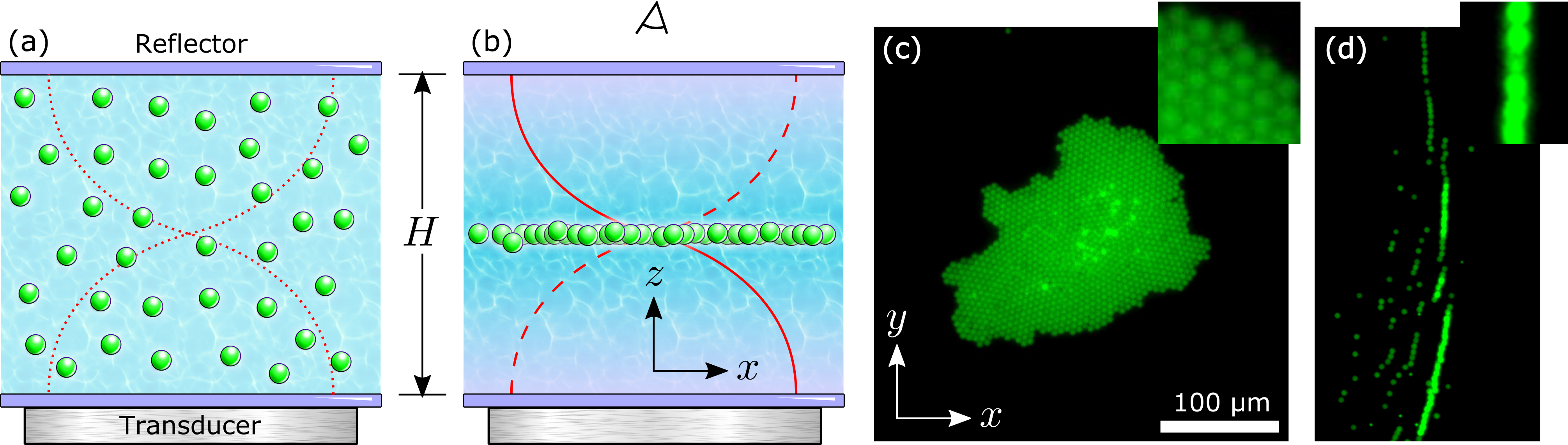
Acoustic standing waves exert forces that can be strong enough to levitate objects against gravity [1] as illustrated schematically in Fig. 1(a) and (b). In addition to experiencing this primary acoustic radiation force (ARF), objects trapped in a standing wave also interact with each other through the sound waves that they scatter. Scattered waves interfere with the standing wave and with each other to mediate secondary Bjerknes forces [2, 3, 4] that generally are attractive at separations smaller than the wavelength of sound. Levitated ensembles of objects therefore tend to organize themselves into planar clusters [5]. When applied to monodisperse spheres, this mechanism creates close-packed crystals [5, 6], such as the example in Fig. 1(c).
Here, we report a distinct mode of sound-mediated organization that arises when acoustic levitation is applied to an emulsion of monodisperse oil droplets in water. Rather than forming crystals, these droplets align themselves into long single-file chains, such as the examples in Fig. 1(d). Video microscopy of the chains suggests that the individual droplets rotate rapidly with a common axis of rotation that is aligned along the chain.
Polymerizing the droplets into solid spheres essentially eliminates their rotation. The solidified spheres no longer form chains, but instead organize themselves into levitated colloidal crystals. Given that polymerization changes nothing about the spheres except for their viscoelastic properties, we propose that the fluid droplets spin because they are deformable and that their spinning gives rise to hydrodynamic interactions that foster chain formation. This mechanism for sound-mediated self-organization appears not to have been reported previously.
Section II presents the model experimental system that exhibits acoustically-driven spinning and chaining. Section III explains how hydrodynamic interactions among spinning spheres can induce chaining, particularly when the spheres inherently are attracted to each other. This analysis reveals a threshold spinning rate above which planar crystals are unstable and single-file chains are favored. Simulations described in Sec. IV then show that chain formation proceeds at a rate consistent with experimental observations given the inferred rate of single-sphere spinning.
II Experimental Observations
II.1 Acoustic levitation
Experiments are carried out in a cylindrical ultrasonic resonator made of aluminium with inner diameter and height . The top of the cavity is sealed with a round quartz cover plate that serves as the reflector shown in Fig. 1(a). The transparent cover also provides optical access to the sample. The bottom is a -thick silicon wafer that launches sound waves into the sample. A standing wave is excited in this resonator by a piezoeletric transducer that is glued directly to the silicon wafer. The disk-like transducer is centered on the wafer to maintain the cylindrical symmetry of the resonator. The transducer is driven sinusoidally by a signal generator (TiePie HandyScope HS5) at amplitudes up to peak to peak [7]. The driving frequency is tuned to the fundamental mode of the cavity with wavelength as depicted in Fig. 1(b). For the experiments reported here, the optimal driving frequency is , which corresponds to a wavelength of in water.
II.2 TPM Droplets
An emulsion of monodisperse fluid droplets is prepared by homogeneous nucleation of 3-(trimethoxysilyl) propyl methyl methacrylate (TPM) (, Sigma Aldrich) in a reducing environment following the procedure described in [8]. All chemicals are used as received with no further purification. The emulsification medium is composed of ammonia (\ceNH3, , Sigma Aldrich) diluted 1000:1 in deionized water (). Droplets are formed by adding of TPM to of the medium at room temperature with gentle stirring for . The diameter of the droplets is then increased by adding more TPM. Four additions of of TPM at intervals increases the final droplet radius to with a polydispersity in radius of . The size and polydispersity of the TPM droplets are measured by holographic particle characterization (Spheryx xSight) and confirmed by dynamic light scattering (Malvern ZetaSizer Nano ZS). The droplets are dyed with FITC to facilitate fluorescence microscopy [8].
A small amount of an oil-soluble free-radical photoinitiator (, Duracure 1173, ciba) is added to the droplets once growth is complete. The photoinitiator is used to polymerize the fluid droplets into solid spheres, but has no influence on their properties until triggered. Completed droplets are transferred to deionized water and are electrostatically stabilized with the addition of sodium dodecyl sulfate (SDS). Holographic characterization measurements confirm that the droplets remain stable and monodisperse for at least 5 weeks.
TPM droplets condensed at low ammonia concentration have a mass density of , as determined by sedimentation equilibrium in a sugar gradient. This is significantly lower than the value of obtained in more strongly reducing media [8]. These droplets have a correspondingly low refractive index of at a vacuum wavelength of as determined by holographic characterization, which is significantly smaller than the value of reported for solid TPM spheres [9]. The density contrast between the droplets and their aqueous environment is large enough to facilitate acoustic trapping but not large enough for gravity to compete effectively with acoustic forces at experimentally accessible pressure levels.
II.3 Solid TPM spheres
TPM droplets are solidified by exposing them to ultraviolet radiation (, ) for to trigger free-radical polymerization. The polymerized TPM spheres have the same mean diameter and polydispersity as their fluid progenitors. Their density, however, increases by to . The increase in density is consistent with the observed increase in refractive index to and also is consistent with results of previous characterization studies [8, 9]. Photopolymerized spheres are washed three times and redispersed in SDS solution.
II.4 Colloidal Imaging
Bright-field and fluorescence images are captured in a Nikon Eclipse Ti widefield fluorescence microscope in reflection mode. The oil-immersion objective provides a system magnification of and the camera records pixel images at with an exposure time of .
II.5 Formation of crystalline monolayers
A dispersion of solid colloidal TPM spheres is driven to the midplane of the ultrasonic levitator in a matter of seconds and forms monolayer crystals in a few minutes. The spheres within a crystal appear to be in contact, as can be seen in the inset to Fig. 1(c) and individual spheres do not appear to move relative to their neighbors once the crystal has formed. Levitated crystals are stable and drift freely in the nodal plane. Crystallization is reversible; turning off the ultrasound frees the spheres to diffuse and sediment independently.
II.6 Chaining of fluid droplets
Performing the same levitation experiments with droplets rather than rigid spheres yields substantially different behavior. Individual droplets appear to vibrate rapidly in the imaging plane, which we interpret to be the projection of rapid rotation around an axis parallel to the imaging plane. Rather than packing into two-dimensional crystals, these droplets form chains that are aligned with the presumed axis of rotation and perpendicular to the axis of the observed vibration. As for the solid-sphere crystals, the droplets within a chain appear to be in contact with each other. Droplet chaining is reversible, and the droplets diffuse apart and sediment as soon as the levitator is turned off.
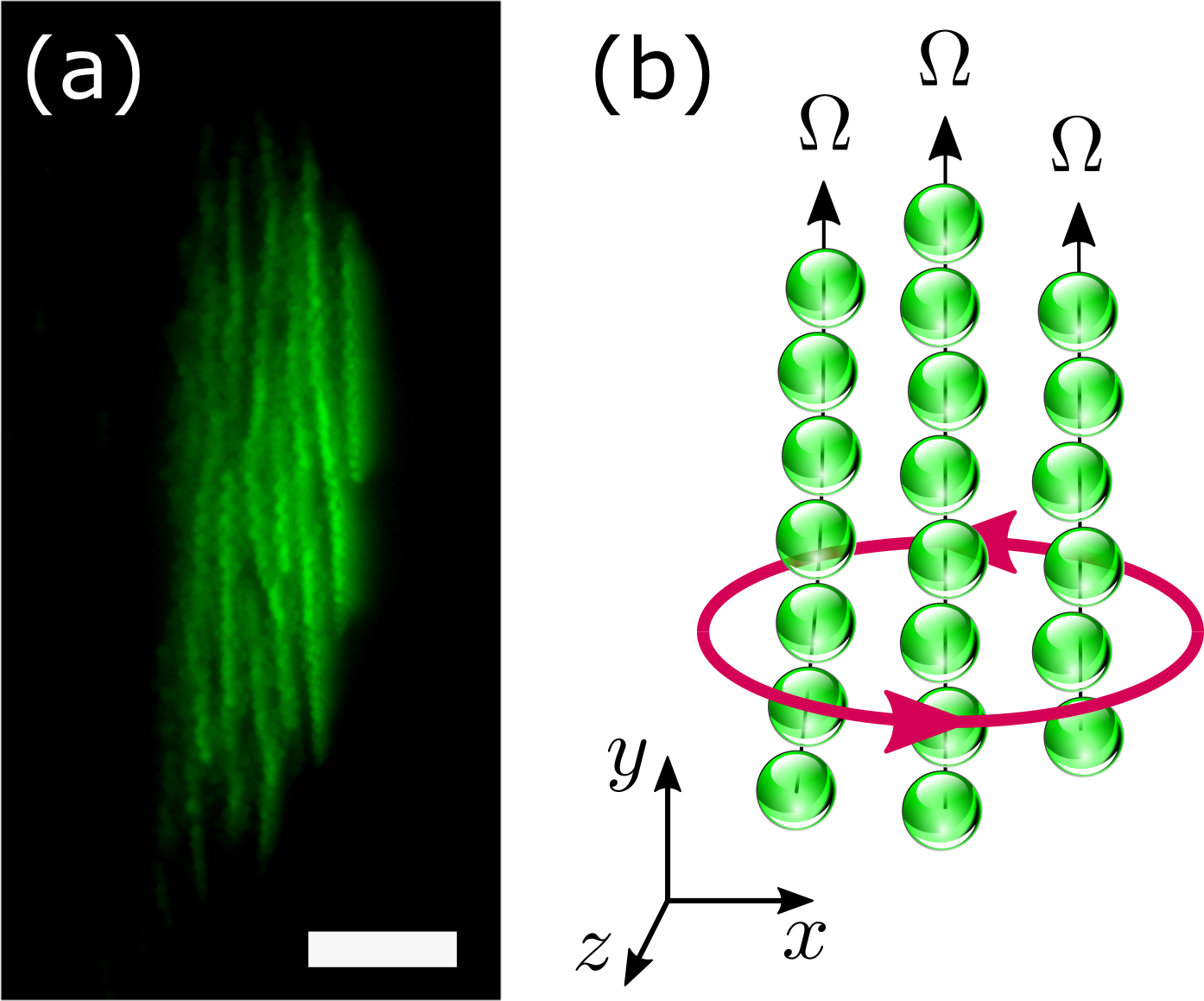
Depending on initial conditions, chains either form in comparative isolation, as in Fig. 1(d), or they form bundles such as the example in Fig. 2(a). The chains within a bundle appear to maintain uniform spacing from each other. They do not appear to exchange droplets. Bundled chains, moreover, tend to orbit each other, as indicated schematically in Fig. 2(b). This orbital motion can be explained naturally if the individual spheres are spinning because the resulting rotational flows would advect neighboring chains. Individual droplets also are observed to orbit nearby chains.
The bundles’ three-dimensional orbital motion carries the spinning droplets tens of micrometers above and below the stable trapping plane near the node of the ultrasonic pressure field. This out-of-plane motion contrasts with the rigid planarity of solid-sphere crystals.
These observations inspire our proposal that individual droplets are driven into rapid rotation by the ultrasonic levitator and that the resulting hydrodynamic coupling among neighboring spheres disrupts crystallization and instead organizes the droplets into chains. The remaining role for acoustic forces is to draw the chained droplets into contact. Similar rotation and chaining has been reported in acoustic levitation experiments on metallic [10] and bimetallic nanorods [11, 12, 13, 14, 15]. Zhou, et al. also report sound-induced rotation of silica-titanium Janus microspheres [10]. The particles in all of these previous reports have lower symmetry than the homogeneous spherical particles and droplets in our experiments. Whereas fluid droplets normally are spherical, they also are deformable and their deformability may contribute to their propensity to spin.
III Acoustohydrodynamic Forces
III.1 Acoustic Forces
Sound transports objects by advecting them in its velocity field and by exerting forces on them through pressure gradients. In a nearly incompressible medium such as water, a sound wave’s pressure, , acts as a scalar potential for the velocity,
| (1) |
where is the wave’s angular frequency and is the mass density of the medium. In this case, the leading-order contributions to the time-averaged force exerted by a harmonic sound wave on a small object may be expressed in terms of the pressure alone as [2, 16]
| (2a) | |||
| where is the wavenumber of the sound in a medium with sound speed . | |||
The acoustic force described by Eq. (2a) depends on the object’s dipole and quadrupole acoustic polarizabilities, and , respectively. These, in turn, depend on the object’s radius, , density, , and sound speed, :
| (2b) | ||||
| (2c) |
Within these expressions, the monopole coupling coefficient,
| (2d) |
depends on the compressibility of the particle, , relative to that of the medium, and the dipole coupling coefficient depends on the density mismatch,
| (2e) |
For TPM in water, and , assuming [17]. Equation (2) should accurately predict acoustic forces experienced by objects that are smaller than the wavelength of sound, . The water-borne TPM droplets and spheres described in Sec. II have a reduced size of when levitated at and so satisfy this condition.
III.1.1 Acoustic levitation
The acoustic levitator used in this study is a resonant cavity whose height, , is adjusted to half a wavelength, , creating a standing pressure wave with a node along the midplane:
| (3) |
This sound wave exerts a primary acoustic force,
| (4) | ||||
| (5) |
that is directed vertically along . Primes in Eq. (4) denote the real parts of the polarizabilities. Equations (2b) through (2e) show that for dense incompressible objects. The levitator therefore localizes such objects near the midplane at with an approximately Hookean restoring force that is proportional to the sound wave’s intensity.
The energy density stored in the standing wave reaches at the maximum driving voltage. This sets the scale for the standing wave’s amplitude through
| (6) |
III.1.2 Secondary Bjerknes interaction
Objects trapped in the levitator interact with each other via scattered sound waves, a mechanism known as the secondary Bjerknes interaction. The nature of this interparticle coupling also may be elucidated with Eq. (2). To leading order in , a small object located at scatters spherical waves to its neighbor at of the form [2]
| (7a) | |||
| where . The scattered pressure field includes a contribution proportional to the pressure of the standing wave at the position of the scatterer with coefficient | |||
| (7b) | |||
| and another term proportional to the standing wave’s velocity with coefficient | |||
| (7c) | |||
The next-higher-order contributions to have gradients directed along and so do not contribute to interparticle interactions.
A particle located at experiences both the levitator’s pressure field and also the scattered field due to its neighbors. Considering just one such interaction, the net pressure wave experienced by a particle at is
| (8) |
which gives rise to a total acoustic force,
| (9) |
that combines the influence of the acoustic trap and the secondary Bjerknes interaction.
Particles trapped near the pressure node at experience and . Their secondary Bjerknes interaction therefore is dominated by the velocity-dependent part of Eq. (7). This is still the case if the particles are displaced slightly from by gravity. Assuming that the trapped particles all have the same physical properties, their secondary Bjerknes interaction reduces to a conservative pairwise-additive force,
| (10) |
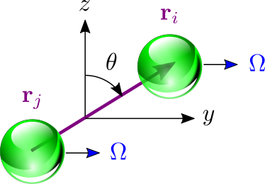
where is the angle between and , as shown in Fig. 3. Equation (10) further reduces to the classic expression for the secondary Bjerknes interaction [2] when the two spheres are in the nodal plane, . This in-plane interaction is isotropically attractive and tends to organize monodisperse spheres into close-packed crystals such as the example in Fig. 1(c). The interaction becomes repulsive if the particles are canted by less than from the vertical. This sign change influences sound-mediated organization when the particles are displaced from the trapping plane by competing influences such as hydrodynamic forces.
Interestingly, depends on the particles’ density through and , but not on their compressibility. The secondary Bjerknes interaction therefore does not distinguish between fluid droplets and solid spheres of the same size and density. Differences in their phenomenology therefore must be due to other mechanisms.
III.2 Hydrodynamic forces
If we accept the proposal that fluid droplets tend to spin rapidly around a common axis in the trapping plane, then their rotation drives circulatory fluid flows that mediate hydrodynamic interactions. Although a definitive explanation for the observed spinning is not yet available, Appendix A presents one possible mechanism. The far-field flow generated by a sphere of radius located at and rotating around the axis at frequency may be modeled as a rotlet,
| (11) |
where is the polar angle indicated in Fig. 3 and is the azimuthal angle around . Equation (11) is a simplifying approximation for the flow field due to a spinning droplet because it does not account for fluid-fluid boundary conditions [18] or for the droplet’s deformations. We also neglect the influence of bounding walls on because the inter-particle separation is much smaller than the distance to the nearest wall.
The flow described by Eq. (11) exerts a hydrodynamic force on a neighboring sphere at that is described by Faxén’s first law:
| (12) |
where is the Stokes drag coefficient in a medium of viscosity . The Laplacian term vanishes in the rotational flow and sphere is simply advected by its neighbor’s flow field.
III.3 Acoustohydrodynamic chaining
The chaining mechanism can be understood by considering the dynamics of two acoustically levitated spheres undergoing coaxial rotation in the trapping plane. By Faxén’s law, the spheres’ center of mass, , moves as
| (13) |
where the dot denotes a derivative with respect to time and is the force of gravity acting on the spheres’ buoyant masses. We assume that is weak enough for the acoustic trapping force to be linear in vertical displacements, as described by Eq. (5). In that case, . We further assume that the spheres’ rotation-induced interaction is reciprocal: .
The spheres’ separation, , evolves as
| (14) |
The secondary Bjerknes interaction tends to draw the spheres into contact. We assume therefore that the relative separation does not not vary significantly, . In spherical coordinates, , the pair’s azimuthal orientation then evolves as
| (15) |
which would describe uniform rotation about if the polar angle, , were fixed. The spheres’ polar orientation also can evolve in time, however, and the full expression for is presented in Appendix B.
Equation (15) has a fixed point, , for , which corresponds to both spheres lying in the horizontal plane at the equilibrium height set by Eq. (13). In this configuration, the spheres’ polar orientation evolves as
| (16) |
The stable configuration with (or equivalently ) corresponds to the spheres aligning along their common rotation axis, . Chaining therefore represents a stable fixed point for the configuration of coaxially spinning particles.
Alternatively, Eq. (15) reveals that stable configurations can appear at , with the spheres separated along , perpendicular to their rotation axis, . The radial component of the hydrodynamic force is repulsive in this configuration [19]. Stable transverse configurations therefore require an independent compensating attraction, such as the secondary Bjerknes force.
Mechanically stable solutions with and are impossible if the spheres’ rotation rate exceeds a critical value,
| (17) |
A transverse pair of rapidly spinning spheres tumbles out of the trapping plane, orbiting the center of mass indefinitely at angular frequency .
Slowly spinning spheres with can be stably oriented at
| (18) |
with respect to the vertical axis. This reflects a mechanical equilibrium between axial acoustic forces and rotation-induced hydrodynamic forces. The non-spinning limit at has a fixed point at , which corresponds to conventional in-plane self-organization mediated by the secondary Bjerknes interaction. An additional fixed point at has the spheres stacked atop each other along the vertical axis, but is unstable. At , the marginally stable transverse configuration is inclined at .
The tumbling solution with remains stationary in the sense that only if . Deviations from transversality allow a tumbling pair to evolve into the aligned state at and therefore to form a chain. This analysis suggests that the combination of acoustic and hydrodynamic forces tends to align pairs of co-rotating spheres along their common axis of rotation provided that their rotation rate is high enough, . For -diameter TPM spheres trapped in our levitator, the critical rotation rate is
| (19) |
The tendency of co-rotating pairs to align along their common axis of rotation inspires us to propose that hydrodynamic forces tend to organize larger ensembles of rapidly-rotating spheres into linear chains while acoustic forces shepherd more slowly rotating particles into planar crystals.
IV Numerical simulations of chain formation
We test the prediction that rotation-mediated acoustohydrodynamic forces create chains through molecular dynamics simulation [20]. The total force acting on the -th sphere in an -sphere cluster is
| (20) |
That sphere’s velocity then depends on all of the forces acting on the system,
| (21a) | |||
| through the Oseen tensor [21], | |||
| (21b) | |||
| that describes hydrodynamic coupling among the spheres. | |||
Equation (21b) incorporates several simplifying assumptions. It ignores inertial effects under the assumption that the spheres’ motions are overdamped. It also neglects diffusion under the assumption that thermal forces are much weaker than either acoustic or hydrodynamic forces. The forces themselves are treated in their leading-order approximations. Leading-order expressions for acoustic forces omit non-conservative and non-additive interactions. The leading-order Oseen tensor does not account for near-field hydrodynamic interactions or lubrication forces. Finally, we assume for simplicity that the spheres all rotate at a fixed rate, , independent of their configuration. Invoking these approximations yields a minimal model for chaining because it is unlikely that any of the omitted effects would tend to promote chain formation over crystallization.
The spheres’ trajectories are calculated by numerically integrating Eq. (21b) with the Euler method. All forces and velocities are recalculated at each time step. Excluded volume interactions are incorporated by backing particles away from collisions [20]. Material parameters are chosen to mimic the experimental system, with rotation rates ranging from to . The 10 particles initially are randomly distributed in a cube centered at the coordinate origin, and then are allowed to reorganize themselves under the influence of acoustic, hydrodynamic and gravitational forces.
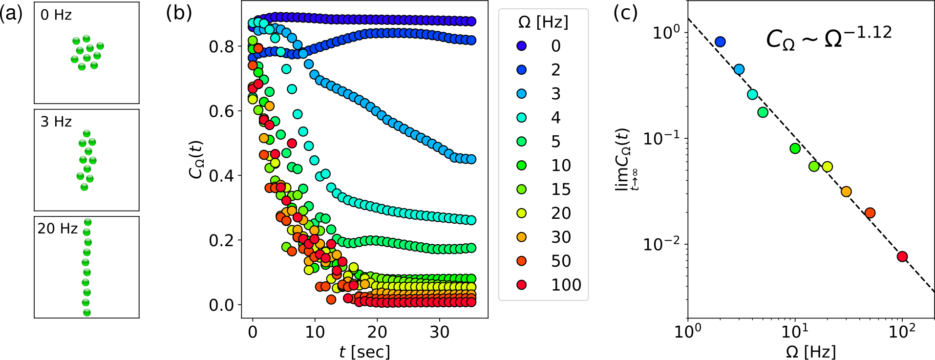
Particles move rapidly toward the trapping plane in these simulations and then reorganize themselves into configurations such as the examples in Fig. 4(a). The set of single-particle trajectories, , can be compared both with predictions of the analytical theory for pair dynamics and also with experimental observations on large collections of spheres. Examples of animated trajectories for slow and fast rotation are presented in the Supplemental Material111See Supplemental Material at [URL will be inserted by publisher] for video animations of molecular dynamics simulations..
We quantify the degree of chaining by computing the projection of the particles’ convex hull in the horizontal plane [23]. The area of the polygonal convex hull, , vanishes for an ideal chain and reaches a maximal value for a compact crystalline cluster. We therefore define a measure of compactness for a system with rotation rate ,
| (22) |
where is the perimeter of the convex hull. This metric approaches for a large crystal and vanishes for a perfectly aligned chain.
Figure 4(b) shows typical examples of the time evolution of for at different values of . As expected, non-rotating spheres form compact clusters while rapidly rotating spheres approach . The transition between these two limiting behaviors appears to be continuous and is consistent with the estimated value of the critical rotation rate, .
The nature of the crystal-to-chain transition is clarified in Fig. 4(c), which shows the long-time asymptotic behavior of as a function of rotation rate. The compactness metric scales as over two orders of magnitude with exponent . This suggests that crystals extend continuously into chains as the spheres spin faster. A typical example of the intermediate state at appears in Fig. 4(a).
These numerical studies confirm that the acoustohydrodynamic model accounts for the observed chaining of TPM fluid droplets in good quantitative agreement with experiment. This mechanism requires the fluid droplets to spin along a common axis at a rate that exceeds a critical value . Solid spheres presumably rotate less rapidly and therefore form conventional compact crystals. Neither the scaling form for the crystal-chain transition nor the observed exponent are yet explained.
V Conclusions
We have demonstrated experimentally, theoretically and in simulations that spinning spheres tend to form chains when levitated by an acoustic standing wave. Hydrodynamic forces engendered by coaxial spinning favor alignment along the common axis. They do not, however, provide the pair attraction required to coalesce clusters of spheres into chains. This attraction is provided in our system by the secondary Bjerknes interaction, which operates independently of the spheres’ spinning.
Spin-mediated hydrodynamic coupling competes with the confining potential of the acoustic levitator. Slowly spinning spheres remain trapped in the plane and so form crystals rather than reorganizing themselves into chains. We anticipate, therefore, that crystals of slowly rotating spheres may only be metastable with respect to chaining but that kinetic barriers to reorganization are prohibitive unless the spheres’ rotation rate is sufficiently high.
We propose that the spheres’ in-plane rotation is driven by inevitable imperfections in the acoustic trap. Estimates based on the parameters for our experimental system suggest that our solid spheres rotate more slowly than the critical rate and therefore form crystals. We propose that fluid droplets of the same material rotate more rapidly because of their deformability in the acoustic force field. This proposal is consistent with experimental observations of fluid droplets’ collective motions. We do not, however, have a complete explanation for this effect, and present it as a outstanding challenge.
Both the tendency of insonated droplets to rotate rapidly and the tendency of co-rotating spheres to form chains appear to be novel phenomena. This mechanism for forming long colloidal chains may be useful for assembling model colloidal polymers [24], linear microrobots [25, 26] and acoustically actuated optical elements [27]. More generally, this study illustrates how the choice of material properties can be used to influence the pathway for sound-mediated self-organization of soft-matter systems.
Acknowledgments
This work was supported primarily by the National Science Foundation through award number DMR-2104837. The Nikon Eclipse Ti microscope and Spheryx xSight particle characterization instrument used for this study were purchased as shared facilities by the NYU Materials Research Science and Engineering Center with support from the NSF under award award number DMR-1420073. M.H. acknowledges support BDI from CNES-CNRS and Aide à la Recherche Grant CNES-France. J.A.D. acknowledges support from the Simons Foundation.
Appendix A Acoustokinetic torque on a sphere
If sound waves incident on or scattered by a particle carry angular momentum, the particle can experience a torque that causes it to spin. This occurs for anisotropic particles in uniform sound fields [13], and for isotropic spheres in nonuniform fields [28, 29]. To dipole order, the time-averaged torque experienced by a sphere at may be expressed in terms of the sound wave’s velocity field as [2]
| (23) |
where is the particle’s acoustic attenuation coefficient. For a fluid droplet of viscosity ,
| (24) |
An ideally rigid sphere has and so experiences no torque and does not spin. This distinction is consistent with our observation that viscoelastic TPM droplets behave differently in an acoustic levitator from solidified TPM spheres.
Expressing a general acoustic pressure field in terms of its real-valued amplitude and phase,
| (25) |
yields an expression for the torque in terms of the structure of the field
| (26) |
that clarifies conditions under which acoustically levitated viscoelastic spheres can spin. An ideal standing wave has no phase gradients, , and so exerts no torque. A perfectly uniform field with similarly exerts no torque. Spheres only experience torques in nonuniform acoustic fields.
To illustrate how acoustic torque might arise in practice, we model the wave launched by the piezoelectric transducer as a plane wave with wave vector and the reflected wave as a plane wave with wave vector :
| (27) |
Expressing in terms of its amplitude and phase,
| (28a) | ||||
| (28b) | ||||
| then leads to | ||||
| (28c) | ||||
| An ideal standing wave has so that the sphere experiences no torque. In practice, however, the incident and reflected waves may be misaligned by a small angle . Orienting the coordinate system so that and is rotated about yields | ||||
| (28d) | ||||
where is the particle’s displacement from the antinode at .
To estimate the scale of the resulting rotation rate, we model a droplet as a sphere with no-slip boundary conditions immersed in a medium of viscosity . Its torque-induced angular velocity is then
| (29) |
which corresponds to a rotation rate on the order of for the present system. This estimate suggests that for TPM spheres in water, which is consistent with the observation that solid TPM spheres do not form chains. The rotation rate is likely to be substantially increased by the deformability of the fluid droplets [13], particularly if resonances enhance their influence [30]. A formulation of this enhancement is not yet available, however, which means that the observed rapid rotation of acoustically levitated fluid droplets is an outstanding challenge.
Appendix B Polar orientation of co-rotating spheres
The polar orientation, , of a pair of corotating spheres evolves in time because of three influences: (1) hydrodynamic interactions that tend to make the spheres tumble out of plane, (2) the primary acoustic force that drives them back toward the nodal plane, and (3) secondary Bjerknes interactions. From Sec. III.2, the hydrodynamic contribution to is
| (30) |
The primary acoustic force contributes
| (31) | ||||
| (32) |
and the contribution due to acoustic interactions, , is
| (33) |
For the stable point analysis in Sec. III.3, the pair of interacting spheres is assumed to be in contact, , because of attractive acoustic interactions. Recognizing that , we retain only the leading term of when deriving Eq. (17).
References
- Brandt [2001] E. H. Brandt, Suspended by sound, Nature 413, 474 (2001).
- Silva [2014] G. T. Silva, Acoustic radiation force and torque on an absorbing compressible particle in an inviscid fluid, J. Acoust. Soc. Am. 136, 2405 (2014).
- Garcia-Sabaté et al. [2014] A. Garcia-Sabaté, A. Castro, M. Hoyos, and R. González-Cinca, Experimental study on inter-particle acoustic forces, J. Acoust. Soc. Am. 135, 1056 (2014).
- Castro and Hoyos [2016] L. A. Castro and M. Hoyos, Determination of the secondary Bjerknes force in acoustic resonators on ground and in microgravity conditions, Microgravity Sci. Technol. 28, 11 (2016).
- Rabaud et al. [2011] D. Rabaud, P. Thibault, M. Mathieu, and P. Marmottant, Acoustically bound microfluidic bubble crystals, Phys. Rev. Lett. 106, 134501 (2011).
- Caleap and Drinkwater [2014] M. Caleap and B. W. Drinkwater, Acoustically trapped colloidal crystals that are reconfigurable in real time, Proc. Nat. Acad. Sci. 111, 6226 (2014).
- Dron and Aider [2012] O. Dron and J.-L. Aider, Acoustic energy measurement for a standing wave in a micro-channel, Europhys. Lett. 97, 44011 (2012).
- Van Der Wel et al. [2017] C. Van Der Wel, R. K. Bhan, R. W. Verweij, H. C. Frijters, Z. Gong, A. D. Hollingsworth, S. Sacanna, and D. J. Kraft, Preparation of colloidal organosilica spheres through spontaneous emulsification, Langmuir 33, 8174 (2017).
- Middleton et al. [2019] C. Middleton, M. D. Hannel, A. D. Hollingsworth, D. J. Pine, and D. G. Grier, Optimizing the synthesis of monodisperse colloidal spheres using holographic particle characterization, Langmuir 35, 6602 (2019).
- Zhou et al. [2017] C. Zhou, L. Zhao, M. Wei, and W. Wang, Twists and turns of orbiting and spinning metallic microparticles powered by megahertz ultrasound, ACS Nano 11, 12668 (2017).
- Wang et al. [2012] W. Wang, L. A. Castro, M. Hoyos, and T. E. Mallouk, Autonomous motion of metallic microrods propelled by ultrasound, ACS Nano 6, 6122 (2012).
- Balk et al. [2014] A. L. Balk, L. O. Mair, P. P. Mathai, P. N. Patrone, W. Wang, S. Ahmed, T. E. Mallouk, J. A. Liddle, and S. M. Stavis, Kilohertz rotation of nanorods propelled by ultrasound, traced by microvortex advection of nanoparticles, ACS Nano 8, 8300 (2014).
- Nadal and Lauga [2014] F. Nadal and E. Lauga, Asymmetric steady streaming as a mechanism for acoustic propulsion of rigid bodies, Phys. Fluid. 26, 082001 (2014).
- Lippera et al. [2019] K. Lippera, O. Dauchot, S. Michelin, and M. Benzaquen, No net motion for oscillating near-spheres at low reynolds numbers, J. Fluid Mech. 866, R1 (2019).
- Dumy et al. [2020] G. Dumy, N. Jeger-Madiot, X. Benoit-Gonin, T. E. Mallouk, M. Hoyos, and J.-L. Aider, Acoustic manipulation of dense nanorods in microgravity, Microgravity Sci. Technol. 32, 1159 (2020).
- Abdelaziz and Grier [2020] M. A. Abdelaziz and D. G. Grier, Acoustokinetics: Crafting force landscapes from sound waves, Phys. Rev. Res. 2, 013172 (2020).
- Xu et al. [2020] G. Xu, Z. Ni, X. Chen, J. Tu, X. Guo, H. Bruus, and D. Zhang, Acoustic characterization of polydimethylsiloxane for microscale acoustofluidics, Phys. Rev. Appl. 13, 054069 (2020).
- Leal [2007] L. G. Leal, Advanced Transport Phenomena: Fluid Mechanics and Convective Transport Processes, Vol. 7 (Cambridge University Press, 2007).
- Jeffery [1915] G. B. Jeffery, On the steady rotation of a solid of revolution in a viscous fluid, Proc. London Math. Soc. 2, 327 (1915).
- Frenkel and Smit [2001] D. Frenkel and B. Smit, Understanding Molecular Simulation: From Algorithms to Applications (Elsevier, 2001).
- Happel and Brenner [2012] J. Happel and H. Brenner, Low Reynolds Number Hydrodynamics: With Special Applications to Particulate Media (Springer, 2012).
- Note [1] See Supplemental Material at [URL will be inserted by publisher] for video animations of molecular dynamics simulations.
- Preparata and Shamos [2012] F. P. Preparata and M. I. Shamos, Computational Geometry: an Introduction (Springer, 2012).
- McMullen et al. [2018] A. McMullen, M. Holmes-Cerfon, F. Sciortino, A. Y. Grosberg, and J. Brujic, Freely jointed polymers made of droplets, Phys. Rev. Lett. 121, 138002 (2018).
- Agrawal and Glotzer [2020] M. Agrawal and S. C. Glotzer, Scale-free, programmable design of morphable chain loops of kilobots and colloidal motors, Proc. Nat. Acad. Sci. 117, 8700 (2020).
- Yang et al. [2020] T. Yang, B. Sprinkle, Y. Guo, J. Qian, D. Hua, A. Donev, D. W. M. Marr, and N. Wu, Reconfigurable microbots folded from simple colloidal chains, Proc. Nat. Acad. Sci. 117, 18186 (2020).
- Martin et al. [1999] J. E. Martin, K. M. Hill, and C. P. Tigges, Magnetic-field-induced optical transmittance in colloidal suspensions, Phys. Rev. E 59, 5676 (1999).
- Zhang and Marston [2011] L. Zhang and P. L. Marston, Acoustic radiation torque and the conservation of angular momentum (l), J. Acoust. Soc. Am. 129, 1679 (2011).
- Toftul et al. [2019] I. D. Toftul, K. Y. Bliokh, M. I. Petrov, and F. Nori, Acoustic radiation force and torque on small particles as measures of the canonical momentum and spin densities, Phys. Rev. Lett. 123, 183901 (2019).
- Di Leonardo et al. [2007] R. Di Leonardo, G. Ruocco, J. Leach, M. J. Padgett, A. J. Wright, J. M. Girkin, D. R. Burnham, and D. McGloin, Parametric resonance of optically trapped aerosols, Phys. Rev. Lett. 99, 010601 (2007).