capbtabboxtable[][\FBwidth]
A Toolchain to Design, Execute, and Monitor Robots Behaviors
Abstract
In this paper, we present a toolchain to design, execute, and verify robots behaviors following the guidelines defined by the EU H2020 project RobMoSys. It models the robot deliberation as a Behavior Tree (BT) whose leaf nodes execute skills modeled as State Charts (SC) running as separate threads. Each state in the SC of a skill corresponds to an actuation or sensing command sent to the robot. The toolchain provides the ability to define runtime monitors that warn the user whenever a given system requirement is violated. We provide a real-robot experimental validation of the toolchain and an OS-virtualization environment to reproduce simulated experiments.
1 Introduction
The design and maintenance of robot software are challenging as we require it to be both reactive and modular. By reactive, we mean the ability to quickly and efficiently react to changes; by modular, we mean the degree to which a system’s components may be separated into building blocks and recombined. Modularity enables components to be developed, tested, and reused independently of one another. Furthermore, robots may operate in open environments unattended, and the unknown and dynamic nature of such environments may jeopardize the robot’s task execution.
This paper describes a model-based toolchain that allows a designer to build and deploy and robot’s behaviors and specification monitors for runtime verification. The approach is based on the framework proposed by the EU H2020 project RobMoSys eu2020project . In particular, we describe the deliberative component as a Behavior Tree (BT) specifying a task-plot, i.e., a sequence of tasks required to achieve certain goals at runtime. The leaves of the BT communicate with skills, i.e., the coordination of functional components made accessible to task-plots; finally, the pieces of software that execute code at the functional layer are components. We focus on runtime verification using monitors, i.e., software components that observe the signals exchanged by the BT, the skills and the components and verify that they are consistent with given requirements. We validate our toolchain in a real robot scenario and provide an OS-virtualization environment based on Docker to reproduce simulated experiments.
2 Behavior Trees
In this section, we briefly describe Behavior Trees (BTs), a detailed description can be found in the literature BTBook . A BT is a directed rooted tree where the internal nodes are sub-behaviors compositions and leaf nodes are either actions to be performed or conditions to be checked. We follow the canonical nomenclature for root, parent, and child nodes. The children of a BT node are placed below it, as in Figure 1, and they are executed from left to right. The execution of a BT begins from the root node. It sends ticks, which are activation signals, with a given frequency to its children. A node in the tree is executed if and only if it receives ticks. When the node no longer receives ticks, its execution stops. The child returns to the parent a status that can be either Success, Running, or Failure according to the logic of the node. Below we present the most common BT nodes and their logic.
Sequence
When a Sequence node receives ticks, it routes them to its children from left to right. It returns Failure or Running whenever a child returns respectively Failure or Running. It returns Success whenever all the children return Success. When child returns Running or Failure, the Sequence node stops sending ticks to the next child (if any) but keeps ticking all the children up to child . The Sequence node is graphically represented by a square with the label “”, as in Figure 1.
Fallback
When a Fallback node receives ticks, it routes them to its children from left to right. It returns a status of Success or Running whenever a child returns Success or Running respectively. It returns Failure whenever all the children return Failure. When child returns Running or Success, the Fallback node stops sending ticks to the next child (if any) but keeps ticking all the children up to the child . The Fallback node is represented by a square with the label “”, as in Figure 1.
Action
An action performs some operations as long as it receives ticks. It returns Success upon completion and Failure if the operations cannot be completed. It returns Running otherwise. When a running Action no longer receives ticks, it aborts its execution. An Action node is graphically represented by a rectangle, as in Figure 1.
Condition
Whenever a Condition node receives ticks, it checks if a proposition is satisfied or not. It returns Success or Failure accordingly. A Condition is graphically represented by an ellipse, as in Figure 1.
3 Toolchain Overview
In this section, we overview the toolchain, starting from the software abstraction layers and then delving into the implementation details.
3.1 Abstraction Layers
The toolchain partitions the robotic software into different layers of abstractions, each addressing different concerns; such organization enables level-specific efficient solutions ahmad2016software . We use the abstraction layers defined by the RobMoSys Robotic Software Component eu2020project that categorize the robotic software in:
Mission Layer
This layer provides the software to design the BT encoding the deliberation policy of the robot to achieve a given goal (e.g., clean the office). It may make use of task planners and optimization algorithms. The toolchain does not provide nor impose any particular solution about this layer, provided that the BT is encoded in a specific form, as described later. In the literature, we find examples where the BT can be synthesized either algorithmically colledanchise2019towards or manually through an API or a GUI-based tool BTBook .
Task Layer
This layer encodes the BT description. We describe the BT using the same eXtended Markup Language (XML) formalism used by Groot111https://github.com/BehaviorTree/Groot and Papyrus4Robotics222https://robmosys.eu/wiki-sn-03/baseline:environment_tools:papyrus4robotics software libraries.
Skill Layer
This layer encodes the basic capabilities (skills) of a robot, e.g., grasp an object, go to a given location in the map, and the like. The specification formalism for skills is State Charts (SC), using the W3C’s scxml formalism333https://www.w3.org/TR/scxml/. In our toolchain, a skill describes the implementation of a leaf node of a BT and orchestrates a set of services from the Service Layer; such orchestration involves retrieving or setting parameters, starting and stopping services, e.g., read a pose from the map server and then send a command to the navigation server to reach that pose. Concerning the execution engine, skills can run in separate executables (also separate from the BT executable), where the source code of the skill is written in a separate component that exposes the interface for calling the functions Tick() and (possibly) Halt(). A leaf node of the BT engine forwards the calls of the functions Tick() and Halt() to the corresponding component. In our toolchain, the YARP middleware handles these calls over the network.
Service Layer
This layer contains entities that serve as access points to sensors and actuators of the robot. It describes the server side of a service that performs basic capabilities (e.g., get the battery level, move the base, etc.).
3.2 Implementation Detail
The toolchain provides two main features: ) Behavior implementation and execution, including the execution of the BT and the SCs, and e runtime monitor execution where property monitors are modeled as SCs. As mentioned above, the BT description can be synthesized either manually or algorithmically. In our example, we manually design the BT using Groot.
The toolchain interprets and executes the XML of the BT using the BehaviorTree.CPP engine444https://www.behaviortree.dev/ while the SCs for the skills and the runtime monitors are executed through the Qt SCXML engine.555https://doc.qt.io/qt-5/qtscxml-overview.html We defined the communication between BT and SCs for skills and between SCs and the components that they orchestrate using an Interface Definition Language (IDL) implemented via the YARP Thirft Remote Procedure Calls (RPCs) and handled via the YARP middleware metta2006yarp , which is synchronous and follows the RobMoSys Query communication pattern666https://robmosys.eu/wiki/modeling:metamodels:commpattern. Components, on the other hand, can communicate with each other using arbitrary communication patterns.
SCs also describe the runtime monitors. At this stage of the toolchain, they are manually synthesized from requirements, but algorithmic generation is feasible and inexpensive for typical properties like safety and response. We use a feature of the YARP middleware called portmonitor paikan2014data to intercept the messages/commands between the BT and the SCs and those between the SCs and the components. The portmonitor then propagates the messages to the SC of the corresponding runtime monitor.
4 Example Scenario
In this example scenario, a service robot has to reach a predefined location. Whenever the battery reaches below % of its full capacity, the robot must stop and reach the charging station, where it waits until a human operator plugs in the power cable and the battery gets fully charged. Once the battery is recharged, the robot resumes the previous task.
4.1 Behavior Tree
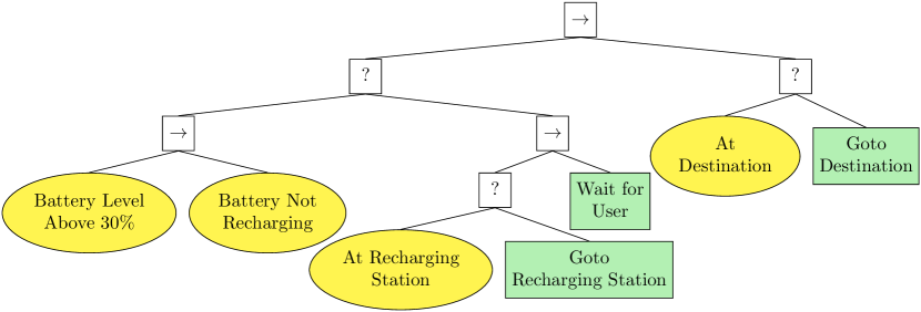
The BT in Figure 1 describes the task above. The BT encodes the following logic:
-
•
The robot checks if the battery level is below % of its capacity or if the battery is charging.
-
•
If the battery level is below % and it is not already under charge, the robot goes to the charging station.
-
•
If the battery level is charging and the robot is at the charging station, the robot waits until the battery gets fully charged.
-
•
If the battery level is above % and it is not under charge, it goes to the destination.
The logic of the leaf nodes of the BT above are:
Battery Level Above 30% (Condition)
It sends a request to a battery reader (a component in the Service Layer) that provides the battery level. The condition returns success if the level is above 30% of its full capacity. It returns failure otherwise.
Battery Not Recharging
It sends a request to a battery reader (a component in the Service Layer) that provides the charging status of the battery (recharging/not recharging). The condition returns success if the battery is not recharging. It returns failure otherwise.
At Location
It sends a request to a localization server (a component in the Service Layer), which provides the robot’s location. The condition returns success if the robot is at the given location. It returns failure otherwise.
Goto Location
It sends a request to a navigation server (a component in the Service Layer), to reach a predefined location, and then it waits for a result from the server (destination reached or path not found). The action returns failure if the navigation server cannot find a path to the destination. It returns success once the robot reaches a destination. It returns running while the robot is navigating. If the action no longer receives ticks, it sends a request to the navigation component to stop the robot’s mobile base.
Wait for User
It returns running (to model an idle state).
4.2 Runtime Monitors
The runtime monitors are SCs that represent behavior specifications. Currently, these SCs are manually designed. The transitions of a SC are triggered upon messages and commands passed as described in Section 3.2 above.
We define two specifications that the robot must fulfill:
-
•
Specification 1: The battery level must never reach below 20%. That is the value read by the condition Battery Level above 30% from the battery reader component must never be less than 20% of the battery capacity. This is because we assume that about 10% of the battery will be sufficient to reach the recharging station from any position.
-
•
Specification 2: Whenever the battery level reaches below 30% of its charge while the robot is going to its destination, the robot must eventually go to the recharging station. That is, the value read by the condition Battery Level above 30% from the battery reader that we should consider to verify this requirement, and then also the commands sent by the action Goto Recharging Station to the navigation components that we should check.
These specifications should ensure that the logic implemented by the BT and the component it orchestrates are correct. In Section 5 below, we show the runtime monitors for these specifications.
5 Experimental results
In this section, we present the experimental results. We performed experiments in a simulated environment, available for reproduction. We also made available the video of the experiments and the code in a pre-installed OS-level virtualization environment to reproduce them.777Please visit https://scope-robmosys.github.io/
Setup
In the simulation environment, the robot is represented with a circle and an orientation. The input of the laser scan is computed by casting, from the center of the robot, virtual radial beams and measuring the collision with a point of the map defined as obstacles. We assume the absence of noise, the absence of uncertainty on the robot’s initial position, and the absence of disturbance on the robot’s movements.
We use an Adaptive Monte Carlo Localization system to localize the robot based on the sensor input and an A∗-based algorithm to compute the path to the destination randazzo2018yarp . The simulated robot has the same software interface of the R1 robot concerning sensors and actuators. Hence, it encodes all the complexity of the real system that are relevant for the action orchestration and monitoring.
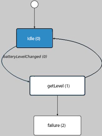
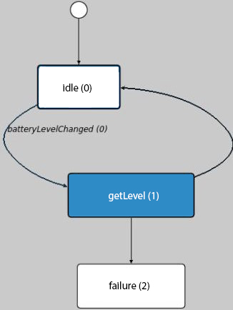
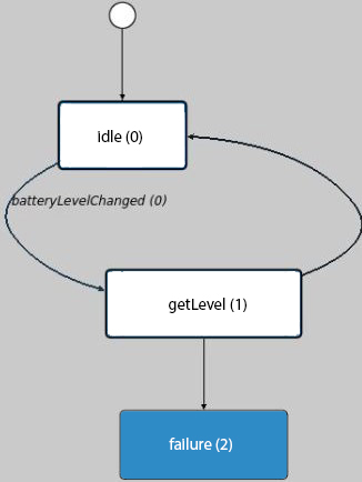
Experiment 1 (Runtime monitor for a safety property)
In this experiment, we show an execution example of the runtime monitor on the battery level specification (Specification 1 in Section 4.2). The monitor implemented is the one depicted in Figure 2(c). In particular, the monitor verifies that the property “The battery level must never reach below 20%” is satisfied throughout the execution. To impose a violation of the property, we manually change the battery level to 10%. Figure 2 shows the execution steps of this experiment for both the scenario and the monitor. At the initial state the battery level is above 30% (Figure 2(a)). The BT sends ticks to the condition “Battery Level Above 30%” and the condition sends a request to the corresponding skill. Then, the skill sends a request to the battery component to read the battery level. The portmonitor detects the request and sends the corresponding message to the runtime monitor and jumps to the state get (Figure 2(c)). When the component replies to the skill, the portmonitor propagates the reply to the runtime monitor. If the battery value is above 20% the monitor moves back to the state idle (Figure 2(d)). Once we manually change the battery level to be 10% (Figure 2(b)) the monitor detects the property violation and it jumps to the state failure (Figure 2(e)).


Experiment 2 (Runtime monitor for a responsive property)
In this experiment, we show an execution example on the runtime monitor on the battery recharging behavior specification (Specification 2 in Section 4.2). The monitor implemented verifies that the property “Whenever the battery level reaches below 30% of its charge, the robot must eventually go to the recharging station” is satisfied throughout the execution.
To impose a violation of the property, we introduce a bug in the SC of the skill “Battery Level Above 30%” such that it returns success while the battery level is above 20%. The execution starts with the robot that plans a path to the destination and follows it (Figure 3(a)). Then, we manually set the battery level to 25%. Due to the bug, the robot keeps moving to the destination (Figure 3(b)). The runtime monitor checks that whenever the battery level goes below 30% the robot eventually moves towards the charging station (Figure 3(d)). It goes to an error state because the battery gets below 30% during the robot navigation and the robot does not reach the charging station (Figure 3(d)).
6 Conclusions
We presented a model-based toolchain to design, execute and monitor robot behaviors. The toolchain follows the RobMoSys meta-model for robot software development. It encodes high-level behaviors in the form of a BT and basic robot capability, in terms of actions and sensing operations, as SCs. The clear separation of the software into different abstraction layers and the communication interfaces defined by Thrift IDL enables an easier design and composition of robot skills and a more effective way to monitor the robot behaviors and detected possible specification violations.
References
- [1] A. Ahmad and M. A. Babar. Software architectures for robotic systems: A systematic mapping study. Journal of Systems and Software, 122:16–39, 2016.
- [2] M. Colledanchise, D. Almeida, and P. Ögren. Towards blended reactive planning and acting using behavior trees. In 2019 International Conference on Robotics and Automation (ICRA), pages 8839–8845. IEEE, 2019.
- [3] M. Colledanchise and P. Ögren. Behavior Trees in Robotics and AI: An Introduction. Chapman and Hall/CRC Artificial Intelligence and Robotics Series. Taylor & Francis Group, 2018.
- [4] R. EU. Project.(2017-2020) robmosys: Composable models and software for robtics systems–towards an eu digital industrial platform for robotics, 2020.
- [5] G. Metta, P. Fitzpatrick, and L. Natale. Yarp: yet another robot platform. International Journal of Advanced Robotic Systems, 3(1):8, 2006.
- [6] A. Paikan, P. Fitzpatrick, G. Metta, and L. Natale. Data flow port monitoring and arbitration. Journal of Software Engineering for Robotics, 5(1):80–88, 2014.
- [7] M. Randazzo, A. Ruzzenenti, and L. Natale. Yarp-ros inter-operation in a 2d navigation task. Frontiers in Robotics and AI, 5:5, 2018.