Control of nonlocal magnon spin transport via magnon drift currents
Abstract
Spin transport via magnon diffusion in magnetic insulators is important for a broad range of spin-based phenomena and devices. However, the absence of the magnon equivalent of an electric force is a bottleneck. In this work, we demonstrate the controlled generation of magnon drift currents in yttrium iron garnet/platinum heterostructures. By performing electrical injection and detection of incoherent magnons, we find magnon drift currents that stem from the interfacial Dzyaloshinskii-Moriya interaction. We can further control the magnon drift by the orientation of the magnetic field. The drift current changes the magnon propagation length by up to relative to diffusion. We generalize the magnonic spin transport theory to include a finite drift velocity resulting from any inversion asymmetric interaction, and obtain results consistent with our experiments.
Introduction. Magnons are collective excitations of ordered magnets that transport spin information without any associated charge motion, unlike electrons. This places magnons and magnon spin currents at the core of an emerging spin-based paradigm for information transport and processing Kruglyak et al. (2010); Kajiwara et al. (2010); Chumak et al. (2015); Kikkawa et al. (2016); Chumak and Schultheiss (2017); Lebrun et al. (2018); Harii et al. (2019); Cornelissen et al. (2015). In a prototypical device Cornelissen et al. (2015); Zhang and Zhang (2012a, b); Takei et al. (2014); Goennenwein et al. (2015); Cornelissen et al. (2016); Li et al. (2016), magnons are injected and detected electrically via the spin Hall effect in two electrically independent but closely spaced heavy metal wires on a magnetic insulator Dyakonov and Perel (1971); Hirsch (1999); Valenzuela and Tinkham (2006); Saitoh et al. (2006); Sinova et al. (2015). A broad range of devices allowing information transport and logic operations - in analogy to electronic devices - have already been accomplished within this paradigm of magnonics Chumak et al. (2014); Ganzhorn et al. (2016); Shan et al. (2017); Lebrun et al. (2018); Cornelissen et al. (2018); Oyanagi et al. (2019); Ross et al. (2019); Wimmer et al. (2019); Avci et al. (2020); Wimmer et al. (2020); Gomez-Perez et al. (2020). In electronics, an electric force on the charge carriers is straightforwardly generated by electric fields. The ensuing electronic drift currents play the central role in various electronic devices Žutić et al. (2004); Manchon et al. (2019). In contrast, magnetic fields do not exert forces on magnons since they do not provide the required inversion symmetry breaking and thus cannot generate magnon drift currents. The generation of magnon drift currents promises to expand the functionality of magnonic devices.
Magnets breaking inversion symmetry allow for an antisymmetric exchange or Dzyaloshinskii-Moriya interaction Dzyaloshinsky (1958); Moriya (1960) (DMI), which is responsible for the emergence of topological spin textures Göbel et al. (2020), the efficient driving of domain walls by spin-orbit torques Vélez et al. (2019); Avci et al. (2019) and the existence of non-reciprocal spin wave modes Wang et al. (2020). The DMI can either stem from the bulk crystal structure Dzyaloshinsky (1958); Moriya (1960) or from interface-induced symmetry breaking in heterostructures including magnetic and nonmagnetic materials Miyawaki et al. (2017); Fert et al. (2017); Bode et al. (2007); Ryu et al. (2013). As a result, engineering the DMI in magnetic heterostructures has become a key focus of research Bode et al. (2007); Ryu et al. (2013); Emori et al. (2013); Chen et al. (2013); Nembach et al. (2015); Ding et al. (2019); Avci et al. (2019); Vélez et al. (2019); Wang et al. (2020).
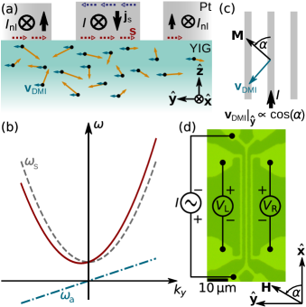
In this Letter, we show that the DMI leads to a finite magnon drift velocity superposed on diffusive spin transport mediated by incoherent magnons. We study nonlocal magnon transport in devices with three parallel, electrically independent Pt wires on yttrium iron garnet (YIG). When driving an electric current through the central injector wire, the interfacial spin accumulation arising from the spin Hall effect excites magnons below the injector (Fig. 1a). In the absence of a magnon drift velocity, an equal amount of magnons diffuse towards the two Pt wires on either side of the injector, leading to identical voltages generated via the inverse spin Hall in either wire. A finite magnon drift velocity due to the interfacial DMI, however, leads to an asymmetric propagation of the injected magnons, resulting in a larger electrical signal on the left wire compared to the right one (Fig. 1a). We show that such a directional transport contribution is present in our YIG/Pt heterostructures and elucidate its interfacial origin from YIG thickness dependent measurements. We generalize the diffusive magnon transport theory to include inversion asymmetry and find good agreement with our experimental observations. Our work shows that nonlocal magnon transport experiments can be used to probe the presence of DMI in magnetic insulators.
Magnon dispersion with DMI. In the presence of DMI and in the limit of small magnon wave vectors , the magnon dispersion relation is superposed to an asymmetric contribution , the slope of which corresponds to the magnon drift velocity Moon et al. (2013); Nembach et al. (2015); Wang et al. (2020) (cf. Fig. 1b). For interfacial DMI with symmetry breaking along Moon et al. (2013); Wang et al. (2020)
| (1) |
where is the angular frequency of the magnon, the gyromagnetic ratio, the saturation magnetization, and the constant quantifying the sign and strength of the DMI. Consequently, the orientation of the drift velocity can be controlled by orienting the magnetization direction Udvardi and Szunyogh (2009); Moon et al. (2013); Nembach et al. (2015) (cf. Fig. 1b). For magnon transport along and when the angle of the magnetic field (and thus of ) with respect to the current direction is given by , we find .
Drift-diffusion model. We first generalize the theory of spin transport driven by the magnon chemical potential in a ferromagnet Cornelissen et al. (2016) to include inversion asymmetry in the system. As introduced above, the magnon dispersion bears a contribution odd in wavevector Udvardi and Szunyogh (2009); Moon et al. (2013); Nembach et al. (2015) leading to a drift-like term in the transport equation Žutić et al. (2004). Separating the symmetric and asymmetric contributions and considering (see Fig. 1b) we limit our considerations to the first order in the drift velocity and thereby assume its effect to be small. As we focus on spin transport driven by the magnon chemical potential Cornelissen et al. (2015, 2016), we assume a constant temperature throughout the system. The spatially resolved magnon density can be expressed as Kittel (2004):
| (2) |
where is the Bose distribution function determining the magnon population, the Boltzmann constant, the magnon chemical potential, and the equilibrium magnon density. As per Eq. (2), the contribution of to the dispersion does not affect the magnon density. The former vanishes when integrating over all as is odd in . The magnon current density, however, now includes a drift contribution stemming from in addition to the diffusive component considered in previous studies Cornelissen et al. (2015, 2016):
| (3) |
where is the magnon diffusion constant Cornelissen et al. (2016), which is independent of the DMI up to first order in . Employing Eqs. (2) and (3) in the continuity equation for magnons and parametrizing the decay of nonequilibrium magnons via a relaxation time , we obtain the transport equation:
| (4) |
The term represents drift and is the only addition as compared to the analogous description for inversion-symmetric systems Cornelissen et al. (2016).
For our quasi-dc nonlocal transport experiments (see Fig. 1), we solve Eq. (4) above in steady state and in the one-dimensional limit, i.e., assuming the chemical potential to depend only on the coordinate. Substituting the ansatz for the magnon chemical potential, we obtain:
| (5) |
The magnon propagation length is thus obtained as:
| (6) |
where is the magnon diffusion length. Thus, we see that the magnon propagation length bears a contribution from drift which can be positive or negative and is controllable via the orientation of the magnetic field given by for the case at hand. Within a simplified model, the nonlocal resistance (i.e., the nonlocal voltage due to magnon propagation divided by the injector current) detected along a given Pt detector wire is proportional to the magnon chemical potential Cornelissen et al. (2016):
| (7) |
where is the injector-detector distance. This expression is valid in the limit of , i.e., when the DMI contribution to the nonlocal transport is small compared to its diffusive counterpart. The dependence arises due to the spin injection and detection via the (inverse) spin Hall effect Cornelissen et al. (2015); Zhang and Zhang (2012a, b).
We conclude that the angular dependence of the nonlocal signal will be altered by the finite drift velocity. Additionally, we note that due to the inversion asymmetric nature of the DMI the second term in Eq. (Control of nonlocal magnon spin transport via magnon drift currents) will change sign when magnon transport along the direction is considered. We thus expect that Eq. (Control of nonlocal magnon spin transport via magnon drift currents) describes the resistance of the left detector and the drift response on the right detector will be opposite.
Experimental Details. YIG films with thickness were grown onto (111)-oriented \chGd3Ga5O12 (GGG) substrates from a stoichiometric \chY3Fe5O12 target with a radio-frequency sputtering system with a base pressure better than . The growth temperature and the Ar pressure during the growth was and , respectively. After deposition, the samples were annealed for at the deposition temperature and finally cooled back to room temperature in vacuum. A thick Pt layer was subsequently deposited in the same chamber at room temperature using dc sputtering in Ar atmosphere at a pressure of . For reference, a YIG/Pt heterostructure was prepared on a thick YIG film grown via liquid phase epitaxy on GGG (see Ref. Schlitz et al. (2019) for details). The formation of a spurious \chGd3Fe5O12 layer at the GGG/YIG interface Gomez-Perez et al. (2018) was excluded via local energy dispersive X-ray spectroscopy (see Ref. SMD ). The Pt films were then patterned into several devices with three parallel wires, having center-to-center separations of to either by optical or electron beam lithography and subsequent Ar ion milling. All investigated devices have a wire width of and a detector length of or .
The measurements were performed in a room temperature electromagnet setup. A sinusoidal current with peak amplitude and frequency was applied to the central wire while to -long time traces of the voltages on the left and right Pt wire were simultaneously acquired and subsequently demodulated to obtain the first harmonic signal (see also Ref. Garello et al. (2013)). This method allows for disentangling the electronic (first harmonic) and thermal (second harmonic) contributions to the measured voltage Cornelissen et al. (2015); SMD . An optical micrograph including the sketched electrical contacts and the definition of the rotation angle is presented in Fig. 1d.
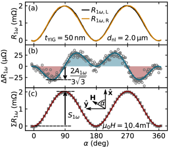
Experimental Results. Figure 2a shows a representative set of nonlocal magnon transport data taken in a device with thick YIG and a wire separation of . For purely diffusive transport, should exhibit a dependence on the in-plane angle of the magnetic field [cf. Eq. (Control of nonlocal magnon spin transport via magnon drift currents)] Cornelissen et al. (2015); Zhang and Zhang (2012a, b). In contrast, we observe that shows a small distortion from the expected shape, which depends on the angle of the magnetic field and differs between the left and right wire. To isolate this asymmetric contribution, we plot the difference between the nonlocal resistance of the two wire in Fig. 2b. reflects the difference in the amount of magnons transported to the left and right wire and corresponds to the second term in Eq. (Control of nonlocal magnon spin transport via magnon drift currents). We indeed find that its angular dependence can be well described by , where quantifies the amplitude of the directional drift contribution. Note that for purely diffusive magnon transport, i.e., when , vanishes Cornelissen et al. (2015). We thus conclude that a finite magnon drift contribution to the nonlocal magnon transport is present in our heterostructures. In particular, magnons are transported more (less) efficiently to the left Pt wire when is between () and (), which is represented by the blue (red) shaded areas in Fig. 2b. The average signal , which includes only the diffusive contribution, is shown in Fig. 2c and closely resembles a with amplitude as expected Cornelissen et al. (2015) [first term in Eq. (Control of nonlocal magnon spin transport via magnon drift currents)]. The current dependence of and as well as a possible effect of the DMI on thermally excited magnon transport is discussed in Ref. SMD .
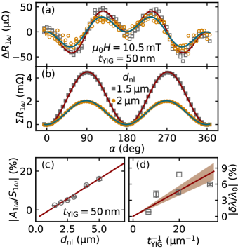
We will now verify that the experimentally observed magnon drift contribution follows the theoretical prediction [Eq. (Control of nonlocal magnon spin transport via magnon drift currents)]. To that end, we characterize the spatial decay of the drift contribution and the diffusive contribution corresponding to the first and second term in Eq. (Control of nonlocal magnon spin transport via magnon drift currents), respectively. Figure 3a and b show representative data of and for devices with and . While the amplitude of decays to , drops to upon increasing . We conclude that the antisymmetric (drift) contribution to the magnon transport (with amplitude ) decays significantly slower than its diffusive counterpart (with amplitude ) as predicted by our theory [cf. Eq. (Control of nonlocal magnon spin transport via magnon drift currents)]. Figure 3c displays the ratio of the antisymmetric and symmetric contributions , which evolves linearly with distance as expected from Eq. (Control of nonlocal magnon spin transport via magnon drift currents) and reaches a maximum value of up to for the largest distance . The slope of the linear fit of is directly proportional to , where [see Eq. (Control of nonlocal magnon spin transport via magnon drift currents)]. is determined by fitting the exponential decay of with for each film Cornelissen et al. (2015). We find in good agreement with the range reported in the literature for nonlocal magnon transport in YIG/Pt heterostructures Goennenwein et al. (2015); Cornelissen et al. (2015); Wimmer et al. (2019) The presence of a directional contribution to the nonlocal transport and its dependence on distance shown in Fig. 3c verify the theoretical predictions and thus further corroborate the origin of the former to be magnon drift currents.
Finally, to pinpoint the origin of the magnon drift velocity, we investigate the dependence of on . Figure 3d shows that for decreasing , the relative drift contribution increases, suggesting that the magnon drift velocity originates from interfacial DMI. This conclusion is consistent with recent reports of interfacial DMI at the GGG/YIG interface, inferred from Brillouin light scattering (BLS) and spin wave spectroscopy measurements Wang et al. (2020), as well as from current-induced domain wall motion experiments in (S)GGG/TmIG/Pt heterostructures Vélez et al. (2019); Avci et al. (2019); Ding et al. (2019). To provide a rough estimate of the DMI strength, we take the logarithmic mean from the reported range Cornelissen et al. (2016); Flebus et al. (2017). From we can thus estimate for the sample with thick YIG, and consequently find [see Eq. (1)]. Considering that the interfacial DMI scales inversely with thickness, we find that agrees within a factor two with recent measurements of GGG/YIG and SGGG/TmIG heterostructures Wang et al. (2020); Vélez et al. (2019). Since the main transport channel is not covered by the Pt layer, we conclude that the DMI originates from the GGG/YIG interface, in agreement with other studies Vélez et al. (2019); Ding et al. (2019); Avci et al. (2019); Wang et al. (2020).
Summary. We have demonstrated a magnon drift contribution to the diffusive nonlocal magnon transport in all-electrical magnon transport devices. The magnon drift velocity can be controlled by the orientation of the magnetic field and gives rise to a characteristic angular dependence. We extended the theory of magnon transport driven by a magnon chemical potential by including magnon drift and found excellent agreement with experiment. Finally, we studied the thickness dependence of the drift contribution, revealing the interfacial origin of the DMI in the YIG/GGG heterostructures. The DMI effectively gives rise to a directional driving force on the magnons, which provides an additional handle to tune the magnon transport properties in nonlocal devices. Magnon drift currents can be realized via various other inversion symmetry-breaking mechanisms and are intrinsic to the materials, paving the way to their application in future devices.
Acknowledgements.
We acknowledge financial support by the Swiss National Science Foundation (SNSF) via projects no. 198642 and 20020_172775, by the Deutsche Forschungsgemeinschaft via SFB 1143 (project no. C08), by the ETH Zürich through the Career Seed Grant SEED-20 19-2, by the Research Council of Norway through its Centers of Excellence funding scheme, project 262633, “QuSpin” and through the Würzburg-Dresden Cluster of Excellence on Complexity and Topology in Quantum Matter - ct.qmat (EXC 2147, project no. 39085490). We also acknowledge the Dresden Center for Nanoanalysis (DCN) at the Technische Universität Dresden and the support of Alexander Tahn and Darius Pohl.References
- Kruglyak et al. (2010) V. V. Kruglyak, S. O. Demokritov, and D. Grundler, Journal of Physics D: Applied Physics 43, 264001 (2010).
- Kajiwara et al. (2010) Y. Kajiwara, K. Harii, S. Takahashi, J. Ohe, K. i. Uchida, M. Mizuguchi, H. Umezawa, H. Kawai, K. Ando, K. Takanashi, S. Maekawa, and E. Saitoh, Nature 464, 262 (2010).
- Chumak et al. (2015) A. V. Chumak, V. I. Vasyuchka, A. A. Serga, and B. Hillebrands, Nature Physics 11, 453 (2015).
- Kikkawa et al. (2016) T. Kikkawa, K. Shen, B. Flebus, R. A. Duine, K. i. Uchida, Z. Qiu, G. E. W. Bauer, and E. Saitoh, Physical Review Letters 117, 207203 (2016).
- Chumak and Schultheiss (2017) A. V. Chumak and H. Schultheiss, Journal of Physics D: Applied Physics 50, 300201 (2017).
- Lebrun et al. (2018) R. Lebrun, A. Ross, S. A. Bender, A. Qaiumzadeh, L. Baldrati, J. Cramer, A. Brataas, R. A. Duine, and M. Kläui, Nature 561, 222 (2018).
- Harii et al. (2019) K. Harii, Y.-J. Seo, Y. Tsutsumi, H. Chudo, K. Oyanagi, M. Matsuo, Y. Shiomi, T. Ono, S. Maekawa, and E. Saitoh, Nature Communications 10, 2616 (2019).
- Cornelissen et al. (2015) L. J. Cornelissen, J. Liu, R. A. Duine, J. B. Youssef, and B. J. van Wees, Nature Physics 11, 1022 EP (2015).
- Zhang and Zhang (2012a) S. S.-L. Zhang and S. Zhang, Physical Review Letters 109, 096603 (2012a).
- Zhang and Zhang (2012b) S. S.-L. Zhang and S. Zhang, Physical Review B 86, 214424 (2012b).
- Takei et al. (2014) S. Takei, B. I. Halperin, A. Yacoby, and Y. Tserkovnyak, Physical Review B 90, 094408 (2014).
- Goennenwein et al. (2015) S. T. B. Goennenwein, R. Schlitz, M. Pernpeintner, K. Ganzhorn, M. Althammer, R. Gross, and H. Huebl, Applied Physics Letters 107, 172405 (2015).
- Cornelissen et al. (2016) L. J. Cornelissen, K. J. H. Peters, G. E. W. Bauer, R. A. Duine, and B. J. van Wees, Physical Review B 94, 014412 (2016).
- Li et al. (2016) J. Li, Y. Xu, M. Aldosary, C. Tang, Z. Lin, S. Zhang, and R. L. J. Shi, Nature Communications 7, 10858 (2016).
- Dyakonov and Perel (1971) M. I. Dyakonov and V. I. Perel, Journal of Experimental and Theoretical Physics Letters 13, 467 (1971).
- Hirsch (1999) J. E. Hirsch, Physical Review Letters 83, 1834 (1999).
- Valenzuela and Tinkham (2006) S. O. Valenzuela and M. Tinkham, Nature 442, 176 (2006).
- Saitoh et al. (2006) E. Saitoh, M. Ueda, H. Miyajima, and G. Tatara, Applied Physics Letters 88, 182509 (2006).
- Sinova et al. (2015) J. Sinova, S. O. Valenzuela, J. Wunderlich, C. H. Back, and T. Jungwirth, Reviews of Modern Physics 87, 1213 (2015).
- Chumak et al. (2014) A. V. Chumak, A. A. Serga, and B. Hillebrands, Nature Communications 5, 4700 (2014).
- Ganzhorn et al. (2016) K. Ganzhorn, S. Klingler, T. Wimmer, S. Geprägs, R. Gross, H. Huebl, and S. T. B. Goennenwein, Applied Physics Letters 109, 022405 (2016).
- Shan et al. (2017) J. Shan, P. Bougiatioti, L. Liang, G. Reiss, T. Kuschel, and B. van Wees, Applied Physics Letters 110, 132406 (2017).
- Cornelissen et al. (2018) L. J. Cornelissen, J. Liu, B. J. van Wees, and R. A. Duine, Physical Review Letters 120, 097702 (2018).
- Oyanagi et al. (2019) K. Oyanagi, S. Takahashi, L. J. Cornelissen, J. Shan, S. Daimon, T. Kikkawa, G. E. W. Bauer, B. J. van Wees, and E. Saitoh, Nature Communications 10, 4740 (2019).
- Ross et al. (2019) A. Ross, R. Lebrun, O. Gomonay, D. A. Grave, A. Kay, L. Baldrati, S. Becker, A. Qaiumzadeh, C. Ulloa, G. Jakob, F. Kronast, J. Sinova, R. Duine, A. Brataas, A. Rothschild, and M. Kläui, Nano Letters 20, 306 (2019).
- Wimmer et al. (2019) T. Wimmer, M. Althammer, L. Liensberger, N. Vlietstra, S. Geprägs, M. Weiler, R. Gross, and H. Huebl, Physical Review Letters 123, 257201 (2019).
- Avci et al. (2020) C. O. Avci, E. Rosenberg, M. Huang, J. Bauer, C. A. Ross, and G. S. D. Beach, Physical Review Letters 124, 027701 (2020).
- Wimmer et al. (2020) T. Wimmer, A. Kamra, J. Gückelhorn, M. Opel, S. Geprägs, R. Gross, H. Huebl, and M. Althammer, Physical Review Letters 125, 247204 (2020).
- Gomez-Perez et al. (2020) J. M. Gomez-Perez, S. Vélez, L. E. Hueso, and F. Casanova, Physical Review B 101, 184420 (2020).
- Žutić et al. (2004) I. Žutić, J. Fabian, and S. Das Sarma, Rev. Mod. Phys. 76, 323 (2004).
- Manchon et al. (2019) A. Manchon, J. Železný, I. M. Miron, T. Jungwirth, J. Sinova, A. Thiaville, K. Garello, and P. Gambardella, Reviews of Modern Physics 91, 035004 (2019).
- Dzyaloshinsky (1958) I. Dzyaloshinsky, Journal of Physics and Chemistry of Solids 4, 241 (1958).
- Moriya (1960) T. Moriya, Physical Review 120, 91 (1960).
- Göbel et al. (2020) B. Göbel, I. Mertig, and O. A. Tretiakov, Physics Reports 895, 1 (2020).
- Vélez et al. (2019) S. Vélez, J. Schaab, M. S. Wörnle, M. Müller, E. Gradauskaite, P. Welter, C. Gutgsell, C. Nistor, C. L. Degen, M. Trassin, M. Fiebig, and P. Gambardella, Nature Communications 10, 4750 (2019).
- Avci et al. (2019) C. O. Avci, E. Rosenberg, L. Caretta, F. Büttner, M. Mann, C. Marcus, D. Bono, C. A. Ross, and G. S. D. Beach, Nature Nanotechnology 14, 561 (2019).
- Wang et al. (2020) H. Wang, J. Chen, T. Liu, J. Zhang, K. Baumgaertl, C. Guo, Y. Li, C. Liu, P. Che, S. Tu, S. Liu, P. Gao, X. Han, D. Yu, M. Wu, D. Grundler, and H. Yu, Physical Review Letters 124, 027203 (2020).
- Miyawaki et al. (2017) J. Miyawaki, S. Suga, H. Fujiwara, M. Urasaki, H. Ikeno, H. Niwa, H. Kiuchi, and Y. Harada, Physical Review B 96, 214420 (2017).
- Fert et al. (2017) A. Fert, N. Reyren, and V. Cros, Nature Reviews Materials 2, 17031 (2017).
- Bode et al. (2007) M. Bode, M. Heide, K. von Bergmann, P. Ferriani, S. Heinze, G. Bihlmayer, A. Kubetzka, O. Pietzsch, S. Blügel, and R. Wiesendanger, Nature 447, 190 (2007).
- Ryu et al. (2013) K.-S. Ryu, L. Thomas, S.-H. Yang, and S. Parkin, Nature Nanotechnology 8, 527 (2013).
- Emori et al. (2013) S. Emori, U. Bauer, S.-M. Ahn, E. Martinez, and G. S. D. Beach, Nature Materials 12, 611 (2013).
- Chen et al. (2013) G. Chen, T. Ma, A. T. N’Diaye, H. Kwon, C. Won, Y. Wu, and A. K. Schmid, Nature Communications 4, 2671 (2013).
- Nembach et al. (2015) H. T. Nembach, J. M. Shaw, M. Weiler, E. Jué, and T. J. Silva, Nature Physics 11, 825 (2015).
- Ding et al. (2019) S. Ding, A. Ross, R. Lebrun, S. Becker, K. Lee, I. Boventer, S. Das, Y. Kurokawa, S. Gupta, J. Yang, G. Jakob, and M. Kläui, Physical Review B 100, 100406(R) (2019).
- Moon et al. (2013) J.-H. Moon, S.-M. Seo, K.-J. Lee, K.-W. Kim, J. Ryu, H.-W. Lee, R. D. McMichael, and M. D. Stiles, Physical Review B 88, 184404 (2013).
- Udvardi and Szunyogh (2009) L. Udvardi and L. Szunyogh, Physical Review Letters 102, 207204 (2009).
- Kittel (2004) C. Kittel, Elementary Statistical Physics (Dover Publications Inc., 2004).
- Schlitz et al. (2019) R. Schlitz, T. Helm, M. Lammel, K. Nielsch, A. Erbe, and S. T. B. Goennenwein, Applied Physics Letters 114, 252401 (2019).
- Gomez-Perez et al. (2018) J. M. Gomez-Perez, S. Vélez, L. McKenzie-Sell, M. Amado, J. Herrero-Martín, J. López-López, S. Blanco-Canosa, L. E. Hueso, A. Chuvilin, J. W. A. Robinson, and F. Casanova, Physical Review Applied 10, 044046 (2018).
- (51) See Supplemental Material at [URL will be inserted by publisher] for local energy-dispersive X-ray spectroscopy of the GGG/YIG interface, for possible contributions of the DMI to the second harmonic nonlocal signal, the current dependence of the nonlocal signal and the definiton of all vectors with respect to the physical systems.
- Garello et al. (2013) K. Garello, I. M. Miron, C. O. Avci, F. Freimuth, Y. Mokrousov, S. Blügel, S. Auffret, O. Boulle, G. Gaudin, and P. Gambardella, Nature Nanotechnology 8, 587 (2013).
- Flebus et al. (2017) B. Flebus, K. Shen, T. Kikkawa, K. i. Uchida, Z. Qiu, E. Saitoh, R. A. Duine, and G. E. W. Bauer, Physical Review B 95, 144420 (2017).
- Meyer et al. (2017) S. Meyer, Y.-T. Chen, S. Wimmer, M. Althammer, T. Wimmer, R. Schlitz, S. Geprägs, H. Huebl, D. Ködderitzsch, H. Ebert, G. E. W. Bauer, R. Gross, and S. T. B. Goennenwein, Nature Materials 16, 977 (2017).