capbtabboxtable[][\FBwidth]
Formalizing the Execution Context of Behavior Trees
for Runtime Verification of Deliberative Policies
Abstract
In this paper, we enable automated property verification of deliberative components in robot control architectures. We focus on formalizing the execution context of Behavior Trees (BTs) to provide a scalable, yet formally grounded, methodology to enable runtime verification and prevent unexpected robot behaviors. To this end, we consider a message-passing model that accommodates both synchronous and asynchronous composition of parallel components, in which BTs and other components execute and interact according to the communication patterns commonly adopted in robotic software architectures. We introduce a formal property specification language to encode requirements and build runtime monitors. We performed a set of experiments, both on simulations and on the real robot, demonstrating the feasibility of our approach in a realistic application and its integration in a typical robot software architecture. We also provide an OS-level virtualization environment to reproduce the experiments in the simulated scenario.
I Introduction
Behavior trees (BTs) are a graphical model to specify reactive, fault-tolerant task executions. Behavior developers introduced them in the computer game industry. They are gaining popularity in robotics because they are highly flexible, reusable, and well suited to define deliberative elements in the model-based design of control architectures. The use of BTs in robotics [1, 2] spans from manipulation [3, 4] to task planning [5, 6], human-robot interaction [7, 8] to learning [9], autonomous vehicles [10], and system analysis [11, 12, 13]. Moreover, BTs are used in the Boston Dynamics’s Spot SDKs to model the robot’s mission111https://www.bostondynamics.com/spot2_0, in the Navigation Stack and the Task Planning System of ROS2 [14, 15].
As elements of control architectures, BTs must concur to satisfy system-wide requirements. These include both safety, e.g., the robot must never put humans or its mission at risk, and response, e.g., the robot should perform its intended tasks. Requirements can be formalized in some logical language so that compliance of BTs and other elements can be algorithmically assessed either off-line, e.g., with static analysis [16, 17] and model checking [18, 19], or on-line, e.g., with runtime verification [20]. The BT literature addresses the verification problem to some extent. There are works providing formal semantics of BTs using either description logic [21], non-linear algebra [22], and pseudocodes [1, 23]; some authors proposed a framework to synthesize BTs that satisfy specifications in Linear Temporal Logic (LTL) [24, 25], and others use LTL to specify the semantics of BT nodes and their composition [26]. However, we argue that these works do not address the problems of embedding BTs in a context including other elements of the software architecture that are required for the BT execution and verifying that the stated requirements are fulfilled in such context.
We tackle these problems by providing a formalization of BTs that considers the elements that they orchestrate, the services provided by the robot at the functional level and the communication among all these elements, and a property specification language to build and deploy monitors for runtime verification. Our approach is consistently based on the framework proposed by RobMoSys222https://robmosys.eu/. In particular, with reference to RobMoSys Composition Structures, we categorize the BT as a task plot, i.e., a sequence of tasks required to achieve certain goals at runtime; the leaves of the BT communicate with skills, i.e., the coordination of functional components made accessible to task-plots; finally, the pieces of software that execute code at the functional layer are components. We argue that ours is a formal, yet scalable, approach that can grant an additional level of confidence when deploying a robot in dynamic and unpredictable environments — a setting where BTs found large advantages over classical task execution architectures.
More specifically, we contribute a model of BTs, skills, components and their interactions in terms of channel systems composed by program graphs [27]. Intuitively, program graphs are extended finite state machines (FSMs) that provide an operational semantics for the execution of single BT nodes, skills and components. The overall system is assembled through communication actions that formalize the parallel execution of the program graphs. We consider both synchronous actions, e.g., to model communication among BT nodes, and asynchronous actions, e.g., to model communication (typically through the middleware) among skill and components, obtaining a globally-asynchronous locally-synchronous model which matches well the actual implementation of the robot’s control architecture. We present a human-readable logic language — a subclass of Timed Propositional Temporal Logic (TPTL) [28] — that enables us to translate requirements into formal properties about data exchanged through channels and extract monitors from them. We chose TPTL over plain Linear Temporal Logic (LTL) because TPTL can express real-time properties like “the robot must start heading towards the charging station at most thirty seconds after receiving a low-battery signal”. A dialect of TPTL, rather than the full logic, was chosen to simplify writing properties in a controlled natural language. We also provide a formal model for the execution of monitors in parallel with other components. Finally, we validate our approach in a service robot scenario, both in simulation and with the R1 humanoid robot [29]. To make our simulated experiments reproducible, we provide the related software in an OS-level virtualization environment based on Docker.
II Scenario
A service robot must go to a predefined location. Whenever the battery goes below % of its full capacity, the robot must stop and reach the charging station, where it waits until the battery gets fully charged. Once the battery gets fully charged, the robot resumes the previous navigation task. Figure 1 shows the BT executed on the robot to accomplish the task. As customary [1], we represent nodes and trees using a graphical syntax, where green rectangles indicate action nodes, yellow ellipses indicate condition nodes, while “” and “?” indicate “sequence” and “fallback” nodes, respectively. The execution of a BT begins with the root receiving a “tick” signal that it propagates to its children. A node in the tree is executed if and only if it receives tick signals. When the node no longer receives ticks, its execution stops. Each child returns to the parent its status, according to the specific logic it implements. In particular, when a sequence node receives ticks, it routes them to its children from the first to the -th. It returns failure or running whenever a child returns so. It returns success whenever all the children return success. The fallback also routes the tick signal to its children from the first to the -th. However, it returns success or running whenever a child returns such status. It returns failure whenever all its children return failure. The logic of the leaf nodes is described below.

Battery Level Above 30% (Condition)
Whenever this condition receives a tick, it sends a request to a battery reader component that provides the battery level. The condition returns success if the battery level is above 30% of its full capacity. It returns failure otherwise.
Battery Not Recharging
Whenever this condition receives a tick, it sends a request to a battery reader component that provides the battery’s charging status. The condition returns success if the battery is not recharging. It returns failure otherwise.
At Location
Whenever this condition receives a tick, it sends a request to a localization component, which implements an Adaptive Monte Carlo Localization [30]. The condition returns success if the robot is at the prescribed location, and failure otherwise.
Goto Location
Whenever this action receives a tick, it sends a request to a navigation component (in our implementation we use the YARP Navigation Stack [30]), and then it waits for the outcome of the navigation (destination reached or path not found). The action returns failure if the navigation component cannot find a collision-free path to Location. It returns success if the robot reaches a destination. It returns running if the robot is navigating towards the destination. Whenever this action receives an halt, it sends a request to the navigation component to stop the robot’s mobile base.
Wait for User
Whenever this condition receives a tick, it returns running.
We impose some requirements on the execution of the BT in Figure 1. The first one is that the battery level must never reach below 20%. More precisely, the value read by the condition Battery Level above 30% from the battery reader component must never be less than 20% of the actual battery capacity. This is because we assume that about 10% of the battery will be sufficient to reach the recharging station from any position. The second requirement is that whenever the battery level reaches below 30% of its charge while the robot is going to its destination, the robot must eventually go to the recharging station; as before, it is the value read by the condition Battery Level above 30% from the battery reader that we should consider to verify this requirement, and then also the commands sent by the action Goto Recharging Station to the navigation components that we should check.
III Representation of BTs
To describe the formal semantics of BTs in their surrounding context, we consider channel systems [27], i.e., parallel systems where processes communicate via first-in-first-out buffers that may contain messages. A channel system formalizes a set of communicating components in which every component can be formalized as a finite state machine running concurrently with others and communication happens asynchronously unless synchronization is forced over channels whose buffers have queues of length 0. The parallel execution of the components is assumed to be asynchronous unless explicit synchronization is provided. Formally, let be a set of processes, and be a set of channels defined as
Let be a set of variables over some domain, where denotes the domain of , and let denote the domain of the messages transmitted over . We can define the set of communication actions as
Actions denoted with a “” are send actions: and send the value of variable or a specific message from to , respectively; actions denoted with “” are receive actions: with and process receives either the value to be assigned to a variable or a specific message from , respectively. A channel has a capacity indicating the maximum number of messages it can store; we denote with the capacity of a channel with . Note that the special case is permitted. In this case, a communication corresponds to synchronous transmission. When , there is a “delay” between the transmission and the receipt of a message, i.e., sending and reading of the same message take place asynchronously. To model processes, we consider a set of variables , where denotes the set of evaluations that assign values to variables, and denotes a set of Boolean conditions over the variables in . For the sake of brevity, we do not introduce conditions formally, but we just mention that they are built using standard Boolean connectives and relational operators over variables. Given a set of channels , communication actions , and variables , a program graph over defined as
where:
-
•
is a set of locations and is a set of actions,
-
•
is the effect function,
-
•
is the transition relation,
-
•
is a set of initial locations,
-
•
is the initial condition.
Given a set of processes where each is specified by a program graph , a channel system over consists of the program graphs over (for ) with .
Intuitively, the transition relation of a program graph over consists of two types of conditional transitions. The conditional transitions are labeled with guards and actions: the condition is the guard of the conditional transition . These conditional transitions can happen whenever the guard holds. Alternatively, conditional transitions are labeled with communication actions. This yields conditional transitions of type with for sending the value of a variable or a specific value along channel , or for receiving variables and values. Based on the current variable evaluation, the capacity and the content of the channel , the guard is satisfied in the following cases:
-
•
Handshaking. When , then process can perform action only if process offers the complementary receive action ;
-
•
Asynchronous message passing. If , then process can perform the conditional transition if and only if channel is empty. Accordingly, may perform the conditional transition if and only if the channel is not empty; if , then the message in the channel is extracted and assigned to , whereas if the message is extracted as long as it is exactly .
The execution of a channel system over is defined formally considering the equivalent transition system, but we skip the definition here since it is not necessary to understand the rest of the paper — details can be found in the literature [27]. One can see the execution of the channel system as the (a)syncrhonous parallel of all the state machines corresponding to the program graphs in the system. At each time, a state machine which can execute an action is chosen non-deterministically to perform that action. In case of synchronous communication actions, two or more state machines will perform transitions accordingly. In case of asynchronous communication actions, or an internal update, only a single machine will make a transition. This behavior abstracts over all possible scheduling techniques that provide some synchronization mechanism among processes.
IV Model
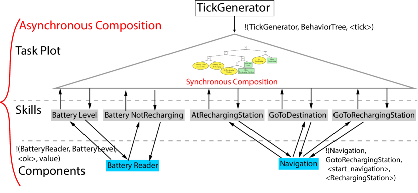
In Figure 2 we show the BT of Figure 1 together with part of its surrounding context. As we mentioned before, we structure all the elements of our design according to the RobMoSys Composition Structures, and the levels relevant for our design are reported in Figure 2. At the task plot level sits the BT, receiving input from a TickGenerator process whose task is simply to keep supplying tick signals to the BT.333The formal notation we introduced in Section III is for closed systems, so we cannot model ticks coming from outside of the BT context. The communication action shown in the figure occurs each time the tick generator sends a tick. The BT itself is a composition of processes, one for each node. We assume that all the nodes exchange messages among them using handshaking, i.e., the BT is a subsystem whose nodes interact in a synchronous way. While we do not give the details of the internal semantics of the nodes here, we wish to point out that this choice enables us to obtain the (compositional) semantics of a BT as a deterministic transition system. In other words, a given BT is guaranteed to execute in the same way given the same inputs, i.e., the tick signal and the messages sent from the skills to the leaves.
In Figure 2 we depict five out of the seven skills required by the BT (skill level) and two components interacting with the skills shown (component level). We assume that each skill and component is modeled either as a single process, or a composition of processes. In the latter case, communication among such processes must occur either through handshaking or shared variables, i.e., asynchronous communication is not allowed inside skills and components, but it is allowed among components. On the other hand, we assume that all the channels among BT, skills and components — depicted as arrows in Figure 2 — have the capacity of one message at a time, i.e., the overall composition is asynchronous. For instance, when requested by the skill BatteryLevel, the component BatteryReader sends back the battery level in the message [ok, value] where value represents the battery level value acquired from the battery driver. Similarly, when the skill GoToRechargingStation is invoked by the BT, it sends to the Navigation component a message [start_navigation, RechargingStations] in order to reach the charging dock.
In our model there is no direct communication from the BT to the components at the functional level. Each skill related to a leaf node in the BT coordinates one of several components to send commands to the robot and computes the return status. This choice is consistent with the RobMoSys Composition Structure diagram.444https://robmosys.eu/wiki/modeling:composition-structures:start Our choice of channels with capacity of a single message at a time implies that no buffering occurs, and this allows us to reproduce very closely concurrency schemes like Remote Procedure Call (RPC). This may look limiting considering the wide adoption of publish-subscribe communication patterns, but it is consistent with the interfaces provided, e.g., by ROS services and YARP modules with RPC interface, which are fairly typical in applications of BTs. In principle, the limitation of a single message per channel can be lifted to model more complex communication patterns, but this would also make verification harder. Finally, we should note that asynchronous composition introduces an element of non-determinism, i.e., scheduling of processes is arbitrary under the assumption that only one transition can be taken at any given time. However, when multiple transition guards are true, the order in which they are taken is arbitrary, and this reflects a level of abstraction with respect to actual scheduling policies.
V Runtime verification
The requirements defined in Section II translate to safety properties, i.e., an event always/never occurs during the execution of the BT, and to response properties, i.e., it must always be the case that if some event occurs during the execution of the BT, then another one must eventually occur at a later time. Formally, violations of safety properties can be found along with the executions of finite length, while response properties can be violated only on executions of infinite length [27]. Safety properties are thus monitorable, but response ones are not, because the response could happen one step beyond the end of any finite trace [20]. To overcome this problem, we formalize properties through a real-time logic so that we can state, e.g., that the robot starts moving to the recharging station within a specific delay after seeing a low battery condition. In the remainder of this section, we introduce a real-time logic language and we show how to formalize requirements and how to extract runtime monitors.
V-A From requirements to formal properties
The syntax of our property specification language is inspired by the OTHELLO language [31], but we consider a semantic-based on timed state sequences [28] instead of one based on hybrid traces [31]. Our language is a fragment of Timed Propositional Temporal Logic (TPTL) [28] and has the grammar shown in Figure 3. We consider the standard abbreviations for Boolean connectives and constants, e.g., we write “false” for “not true”, “ implies ” for “not or ”; similarly, for temporal connectives we write “eventually ” for “true until ” and “always ” for “not eventually not ”. The main feature of SCOPE is that atoms are always related to channel events, i.e., Boolean conditions that become true when specific values are transmitted over channels. We consider two kinds of events: untimed events do not have a time delay associated with them, e.g., the atom is either or true or false at a specific point in time depending on the contents of the channel from BatteryReader to BatteryLevel; on the other hand, timed events have a time window associated with them, e.g., the atom is either true or false depending on the contents of the channel between BatteryReader and BatteryLevel within 10 time steps from the current point in time, i.e., the channel must contain the message with at least once within 10 time steps.
| constraint | := | atom |
| not constraint | ||
| constraint or constraint | ||
| constraint and constraint | ||
| next constraint | ||
| constraint until constraint | ||
| ( constraint ); | ||
| atom | := | true event |
| time_until ( event ) relop const; | ||
| event | := | ( source , dest , condition ) |
| condition | := | message relop const |
| not condition | ||
| condition or condition | ||
| condition and condition |
We give here a brief and mostly informal account about the semantics of SCOPE, leaving the details to [32] from which we borrow the notation and the definitions. The meaning of SCOPE constraints is given in terms of timed state sequences generated by a channel system like the one described in Section IV and shown in Figure 2. The component TickGenerator provides (discrete) time sequences , i.e., sequences of tick identifiers and . The first tick generated will have identifier 0, then 1, 2, and so on. We assume that time sequences are initialized, i.e., , monotonic, i.e., for all and progressive, which means that for all there is some such that . Let represent the set of channels connecting the tick generator, the BT, the skills and the components, and be the set of evaluations on such channels. The execution of the overall system provides state sequences where and . A timed state sequence (TSS) is a pair consisting of a state sequence and a time sequence where . Intuitively, a TSS pairs a tick identifier with a channel evaluation being consistent with that identifier. Note that the same tick identifier might occur several times in a TSS because a single tick usually implies a number of changes in the overall channel evaluation as signals are propagated from the BT to skills and to components without new ticks being generated.
We write to denote that the SCOPE constraint is sastified by the TSS . This relationship is formally described for TPTL in [32] and thus holds also for our fragment SCOPE. Intuitively, Boolean formulas are satisfied at any point of a TSS if the evaluation makes the formula true, and temporal connectives have the usual meaning: next is satisfied at a point in time if is satisfied at the next one; until is satisfied if holds until eventually does. Timed events are handled as expected. For instance, time_until ( ) is satisfied at a point in time if event occurs within step (excluded), whereas time_until ( ) is satisfied at a point in time if event occurs exactly at step . Given a channel system an execution of is any TSS consistent with the process composition, assuming that at least one process provides the signal for the time trace — in our case, it is TickGenerator. Given a SCOPE constraint whose events occur over the channels of , we write when satisfies the constraint , i.e., for all the executions of we have that . The safety and response requirements on the scenario described in Section II become the SCOPE properties depicted in Figure 4, where is some user-specified constant threshold.
V-B From formal properties to runtime monitors
The literature provides a general monitoring algorithm for TPTL properties [32]. We could resort to that procedure in order to obtain monitors from properties written in SCOPE. However, since SCOPE is a fragment of TPTL and we are interested in properties having a specific structure, we are able to obtain even more compact and efficient monitors. In Figure 5 we show the monitors (specified as program graphs) extracted from the properties stated above: Figure 5(a) shows the monitor for the safety property and Figure 5(b) shows the monitor for the response property . Looking at Figure 5(a), we can observe that the safety monitor makes a transition from the initial location I whenever the value of the battery charge is transmitted from the component BatteryReader to the skill BatteryLevel. Intuitively, the monitor “sniffs” from the channel the value transmitted checking whether it is greater than or equal to 20, or less than 20: in the first case, it returns to the initial location, waiting for new messages; in the second case, it enters the location Err to signal that the property was violated in the current execution. In Figure 5(b), we can observe that the response monitor makes a transition to the state I1 whenever the navigation component is answering running to the GoToDestination skill, meaning that the robot is making its way to the destination. When the value of the battery charge is transmitted, the monitor moves to state C1: if the value is above 30, the monitor goes back to state I1; otherwise, it goes to state S, where a further transition sets the variable timer to and moves to state C2. Here, two things may happen: either the monitor detects a message on the channel from the skill GotoDestination to the component Navigation commanding the latter to go to the recharging station or the monitor detects a tick sent to the behavior tree. In the former case, the monitor “resets” to the initial state I, as the response property was fulfilled within ticks sent to the BT. In the latter case, it checks whether timer reached 0, in which case it enters an error state, while if timer is still greater than 0 it decrements timer and goes back in state C2 to wait for messages. While the program graphs described in Figure 5 are specific to properties and , it is easy to see how the construction can generalize to safety and response properties having the same structure.


The last element that remains to be added to our description is
the interaction of monitors with the other processes in the channel
system of Figure 2. Let
over be the channel
system with added monitor . We introduce
the concept of monitored transition to allow monitors to make
transitions based on channel values without interfering with other
processes. For instance, let us consider monitoring asynchronous
message passing for channel , when process
receives a value from process and assigns it
to variable with , while
monitor assigns it to variable with . Given and as
current evaluations of variables and channels, respectively, the rule
for such a transition is:
| (1) |
where and . Notice that the evaluation of both and is changed, and the location change occurs in the processes as well as in the monitor. Intuitively, the rule “forces” a synchronous transition between the component(s) to be monitored and the corresponding monitor, to make sure that all relevant signals are processed by the monitor at the same time in which they are transmitted. In practice, for instance in publish/subscribe middleware, this action can be simply implemented by having the monitor subscribe to all the topics of interest; clearly, we expect that only published topics will be subject to monitoring. All the other rules for transitions involving an exchange of data, including those for handshaking, can be modified in a similar way to take into account monitors. If multiple monitors are sniffing a specific channel, then the transition should include all of them at once, i.e., the update of monitors sniffing the same channel is synchronized.
VI Experimental results
In this section, we present the experimental results. We made available the video555https://youtu.be/ipLpRIh7Sp4 of the experiments and the code in a pre-installed OS-level virtualization environment666github.com/SCOPE-ROBMOSYS/IROS2021-experiments to reproduce them.
Toolchain Overview
We implemented the BT using the BehaviorTree.CPP engine777https://github.com/BehaviorTree/BehaviorTree.CPP and Finite State Machines (FSMs) for the skills and the runtime monitors using the Qt SCXML engine.888https://doc.qt.io/qt-5/qtscxml-overview.html We defined the communication between BT and each skill FSM, and between a skill FSM and the components it orchestrates using an Interface Definition Language handled via the YARP middleware [33]. We use a feature of the YARP middleware called portmonitor [34] to transparently intercept the communication between the BT and the skills and between the skills and the components. The portmonitor then propagates the messages to the FSM of the corresponding runtime monitor.
Real Robot
We tested our approach on the IIT R1 [29] robot. Concerning the navigation capabilities, the robot’s wheeled base is equipped with two laser scanners, one at the front and one at the back. We employ an Adaptive Monte Carlo Localization system to localize the robot and an A∗-based algorithm to compute the path to the destination [30]. The algorithms rely on the odometry and the laser scan inputs.
Simulation Environment
The robot is represented in the map as a circle and an orientation. Starting from the center of the robot’s representation, we compute the input of the laser scanner by casting radially polarized beams, and we measure the collision on a point of the map labeled as obstacles. We do not model sensor noise. We assume the absence of uncertainty on the robot’s initial position and we do not model the disturbance on the robot movements. We employ the same localization and navigation system of the real IIT R1. Notice that the simulated robot has the same software interface of IIT R1 when it comes to sensors and actuators. Therefore, it captures all the complexity of the real system relevant to our work. Moreover, the runtime monitor mechanisms will detect possible misbehaviors of the simulated model caused by wrong assumptions about the model itself.
Experiment 1 (Runtime monitor for a safety property)
This experiment, executed in the simulated environment, shows an execution example of the runtime monitor on the battery level on the scenario described in Section II. The monitor implemented is the one depicted in Figure 5(a). In particular, the monitor verifies that the property holds, i.e. “The battery level must never reach below 20%” (see Section V). To impose a property’s violation, we inject a fault in the system by manually changing the level of the battery. Figure 6 shows the execution steps, of both the scenario and the monitor, of this experiment. Initially, the battery level is above 30% (Figure 6(a)). The BT sends ticks to the condition “Battery Level Above 30%” and the condition sends a request to the corresponding skill. Then, the skill sends a request to the battery component to request the battery level. The portmonitor detects the request and sends the corresponding message to the runtime monitor, which goes to the state get (Figure 6(c)). When the component replies to the skill, the portmonitor propagates the reply to the runtime monitor. While the battery value is above 20% the monitor moves back to the state idle (Figure 6(d)). When we manually impose the battery level to be 10% (Figure 6(b)) the monitor detects the property violation, thus it goes to the state failure (Figure 6(e)).


Experiment 2 (Runtime monitor for a responsive property)
This experiment, executed in the simulated environment, shows an execution example on the runtime monitor on the battery recharging behavior. The monitor implemented is the one depicted in Figure 5(b). In particular, the monitor verifies that the property holds, i.e. “Whenever the battery level reaches below 30% of its charge, the robot must eventually go to the recharging station” (see Section V). To impose a property’s violation, we introduce a bug in the FSM of the skill “Battery Level Above 30%” such that it returns success while the battery level is above 20%. The execution is similar to the one of Experiment 1. The runtime monitor goes to an error state because the battery gets below 30% during the robot navigation and before it gets to the charging station.
Experiment 3 (Monitor on a real robot)
This experiment shows the execution with a safety property violation in a real robot scenario. In particular, the monitor verifies that the property holds, i.e. “The battery level must never reach below 20%” (see Section V). To impose a property’s violation, a malicious user tampers with the robot control system, moving it with a joypad that overrides the navigation commands, impeding the robot from reaching the charging station.
Figure 7 shows the execution steps of this scenario, while Figure 8 shows the FSM of the runtime monitor. When the battery level gets below 30%, the robot moves towards the charging station (Figure 7(a)). While the robot moves towards the charging station, a malicious user moves the robot elsewhere (Figure 7(b)). Then the robot resumes the navigation (Figure 7(c)), and the malicious user moves the robot elsewhere again. After several inputs from the malicious user, the battery level gets below 20% (Figure 7(d)) and the monitor detects the violation of the property (Figure 8(b)).


VII Concluding Remarks
We formalized the execution context of BTs and obtained runtime monitors from robot task requirements. We provided experimental evidence that deliberative level control can be formalized in a natural yet precise way and that such formalization can be easily embedded in model-based design workflows [22, 26]. Finally, we implemented our approach on a real robot with BTs at it’s the deliberative level.
The formalization of the execution context and the monitor generation enable the runtime verification of policies in form of BTs. Nevertheless, while the RobMosys framework motivates our choice of using BTs, our approach can be applied to any deliberation model that admits a semantic representation in terms of compositions of state machines.
We can automate our approach by generating the monitors for the formal properties considered in this paper algorithmically. State-of-the-art approaches [32] suggest that automatic generation can be done in polynomial time. This allows us to scale our approach efficiently, providing a middleware that can route all the monitored signals efficiently.
References
- [1] M. Colledanchise and P. Ögren, Behavior Trees in Robotics and AI: An Introduction, ser. Chapman and Hall/CRC Artificial Intelligence and Robotics Series. Taylor & Francis Group, 2018.
- [2] R. Ghzouli, T. Berger, E. B. Johnsen, S. Dragule, and A. Wasowski, “Behavior trees in action: a study of robotics applications,” in Proceedings of the 13th ACM SIGPLAN International Conference on Software Language Engineering, 2020, pp. 196–209.
- [3] F. Rovida, B. Grossmann, and V. Krüger, “Extended behavior trees for quick definition of flexible robotic tasks,” in 2017 IEEE/RSJ International Conference on Intelligent Robots and Systems (IROS). IEEE, 2017, pp. 6793–6800.
- [4] D. Zhang and B. Hannaford, “Ikbt: solving symbolic inverse kinematics with behavior tree,” Journal of Artificial Intelligence Research, vol. 65, pp. 457–486, 2019.
- [5] X. Neufeld, S. Mostaghim, and S. Brand, “A hybrid approach to planning and execution in dynamic environments through hierarchical task networks and behavior trees,” in Fourteenth Artificial Intelligence and Interactive Digital Entertainment Conference, 2018.
- [6] E. Safronov, M. Colledanchise, and L. Natale, “Task planning with belief behavior trees,” in 2020 IEEE/RSJ International Conference on Intelligent Robots and Systems (IROS). IEEE, 2020, pp. 6870–6877.
- [7] N. Axelsson and G. Skantze, “Modelling adaptive presentations in human-robot interaction using behaviour trees,” in Proceedings of the 20th Annual SIGdial Meeting on Discourse and Dialogue, 2019.
- [8] A. Ghadirzadeh, X. Chen, W. Yin, Z. Yi, M. Björkman, and D. Kragic, “Human-centered collaborative robots with deep reinforcement learning,” IEEE Robotics and Automation Letters, vol. 6, no. 2, pp. 566–571, 2020.
- [9] B. Banerjee, “Autonomous acquisition of behavior trees for robot control,” in 2018 IEEE/RSJ International Conference on Intelligent Robots and Systems (IROS). IEEE, 2018, pp. 3460–3467.
- [10] C. I. Sprague, Ö. Özkahraman, A. Munafo, R. Marlow, A. Phillips, and P. Ögren, “Improving the modularity of auv control systems using behaviour trees,” in 2018 IEEE/OES Autonomous Underwater Vehicle Workshop (AUV). IEEE, 2018, pp. 1–6.
- [11] O. Biggar, M. Zamani, and I. Shames, “A principled analysis of behavior trees and their generalisations,” arXiv preprint arXiv:2008.11906, 2020.
- [12] P. de la Cruz, J. Piater, and M. Saveriano, “Reconfigurable behavior trees: towards an executive framework meeting high-level decision making and control layer features,” in 2020 IEEE International Conference on Systems, Man, and Cybernetics (SMC). IEEE, 2020, pp. 1915–1922.
- [13] P. Ögren, “Convergence analysis of hybrid control systems in the form of backward chained behavior trees,” IEEE Robotics and Automation Letters, vol. 5, no. 4, pp. 6073–6080, 2020.
- [14] S. Macenski, F. Martín, R. White, and J. G. Clavero, “The marathon 2: A navigation system,” in 2020 IEEE/RSJ International Conference on Intelligent Robots and Systems (IROS). IEEE, 2020, pp. 2718–2725.
- [15] F. Martín, J. Ginés, F. J. Rodríguez, and V. Matellán, “Plansys2: A planning system framework for ros2,” in IEEE/RSJ International Conference on Intelligent Robots and Systems, IROS 2021, Prague, Czech Republic, September 27 - October 1, 2021. IEEE, 2021.
- [16] M. S. Hecht, Flow analysis of computer programs. Elsevier Science Inc., 1977.
- [17] P. Cousot and R. Cousot, “Abstract interpretation: A unified lattice model for static analysis of programs by construction or approximation of fixpoints,” in Conference Record of the Fourth ACM Symposium on Principles of Programming Languages, Los Angeles, California, USA, January 1977, R. M. Graham, M. A. Harrison, and R. Sethi, Eds. ACM, 1977, pp. 238–252.
- [18] J.-P. Queille and J. Sifakis, “Specification and verification of concurrent systems in cesar,” in International Symposium on programming. Springer, 1982, pp. 337–351.
- [19] E. M. Clarke, E. A. Emerson, and A. P. Sistla, “Automatic verification of finite-state concurrent systems using temporal logic specifications,” ACM Transactions on Programming Languages and Systems (TOPLAS), vol. 8, no. 2, pp. 244–263, 1986.
- [20] M. Leucker and C. Schallhart, “A brief account of runtime verification,” The Journal of Logic and Algebraic Programming, vol. 78, no. 5, pp. 293–303, 2009.
- [21] A. Klöckner, “Interfacing behavior trees with the world using description logic,” in AIAA Guidance, Navigation, and Control (GNC) Conference, 2013, p. 4636.
- [22] M. Colledanchise and P. Ögren, “How Behavior Trees Modularize Hybrid Control Systems and Generalize Sequential Behavior Compositions, the Subsumption Architecture, and Decision Trees,” IEEE Transactions on Robotics, vol. 33, no. 2, pp. 372–389, April 2017.
- [23] E. Giunchiglia, M. Colledanchise, L. Natale, and A. Tacchella, “Conditional behavior trees: Definition, executability, and applications,” in 2019 IEEE International Conference on Systems, Man and Cybernetics (SMC). IEEE, 2019, pp. 1899–1906.
- [24] M. Colledanchise, R. M. Murray, and P. Ögren, “Synthesis of correct-by-construction behavior trees,” in 2017 IEEE/RSJ International Conference on Intelligent Robots and Systems (IROS). IEEE, 2017, pp. 6039–6046.
- [25] J. Tumova, A. Marzinotto, D. V. Dimarogonas, and D. Kragic, “Maximally satisfying ltl action planning,” in 2014 IEEE/RSJ International Conference on Intelligent Robots and Systems. IEEE, 2014, pp. 1503–1510.
- [26] O. Biggar and M. Zamani, “A framework for formal verification of behavior trees with linear temporal logic,” IEEE Robotics and Automation Letters, vol. 5, no. 2, pp. 2341–2348, 2020.
- [27] C. Baier and J.-P. Katoen, Principles of model checking. MIT press, 2008.
- [28] R. Alur and T. A. Henzinger, “A really temporal logic,” J. ACM, vol. 41, no. 1, pp. 181–204, 1994.
- [29] A. Parmiggiani, L. Fiorio, A. Scalzo, A. V. Sureshbabu, M. Randazzo, M. Maggiali, U. Pattacini, H. Lehmann, V. Tikhanoff, D. Domenichelli et al., “The design and validation of the r1 personal humanoid,” in 2017 IEEE/RSJ international conference on intelligent robots and systems (IROS). IEEE, 2017, pp. 674–680.
- [30] M. Randazzo, A. Ruzzenenti, and L. Natale, “Yarp-ros inter-operation in a 2d navigation task,” Frontiers in Robotics and AI, vol. 5, p. 5, 2018.
- [31] A. Cimatti, M. Roveri, A. Susi, and S. Tonetta, “Validation of requirements for hybrid systems: A formal approach,” ACM Transactions on Software Engineering and Methodology (TOSEM), vol. 21, no. 4, pp. 1–34, 2013.
- [32] A. Dokhanchi, B. Hoxha, C. E. Tuncali, and G. E. Fainekos, “An efficient algorithm for monitoring practical TPTL specifications,” in 2016 ACM/IEEE International Conference on Formal Methods and Models for System Design, MEMOCODE 2016, Kanpur, India, November 18-20, 2016. IEEE, 2016, pp. 184–193.
- [33] G. Metta, P. Fitzpatrick, and L. Natale, “Yarp: yet another robot platform,” International Journal of Advanced Robotic Systems, vol. 3, no. 1, p. 8, 2006.
- [34] A. Paikan, P. Fitzpatrick, G. Metta, and L. Natale, “Data flow port monitoring and arbitration,” Journal of Software Engineering for Robotics, vol. 5, no. 1, pp. 80–88, 2014.